Overview

This chapter contains the following sections:

Cisco UCS B480 M5 Blade Server

The Cisco UCS B480 M5 is a density-optimized, full-width blade server that supports four CPU sockets for the Intel Xeon Processor Scalable Family of CPUs. The server supports the following features:

  • 48 DDR4 DIMMs

  • 2 front mezzanine modules (storage or graphics processing unit (GPU))

  • 1 modular LAN on motherboard (mLOM) module

  • 2 rear mezzanine modules (I/O or GPU)

  • A mini-storage module socket with these options:

    • SD card module with two SD card slots

    • M.2 module with slots for two SATA M.2 drives

    • Cisco Boot-Optimized M.2 RAID Controller (module with two slots for SATA M.2 drives, plus an integrated SATA RAID controller that can control the two M.2 drives in a RAID 1 array)

You can install up to four UCS B480 M5 blade servers in a UCS 5108 chassis, mixing with other models of Cisco UCS blade servers in the chassis if desired.
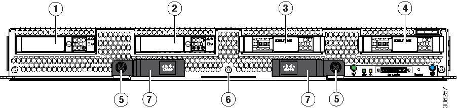
Figure 1. Cisco UCS B480 M5 Blade Server Front Panel
Figure 2. Cisco UCS B480 M5 Blade Server Front Panel LEDs

1

Drive bay 1

2

Drive bay 2

3

Drive bay 3

4

Drive bay 4

5

Ejector thumb screw

6

Asset pull tag

7

Blade ejector handle
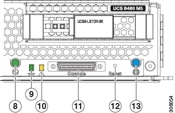
8

Power button and LED

9

Network link status LED

10

Blade health LED

11

Local console connection

12

Reset button

13

Locate button and LED

External Features Overview

The features of the blade server that are externally accessible are described in this section.

LEDs

Server LEDs indicate whether the blade server is in active or standby mode, the status of the network link, the overall health of the blade server, and whether the server is set to give a blinking blue locator light from the locator button.

The removable drives also have LEDs indicating hard disk access activity and disk health.

Table 1. Blade Server LEDs

LED

Color

Description

Power

Off

Power off.

Green

Main power state. Power is supplied to all server components and the server is operating normally.

Amber

Standby power state. Power is supplied only to the service processor of the server so that the server can still be managed.

Note 

The front-panel power button is disabled by default. It can be re-enabled through Cisco UCS Manager. After it's enabled, if you press and release the front-panel power button, the server performs an orderly shutdown of the 12 V main power and goes to standby power state. You cannot shut down standby power from the front-panel power button. See the Cisco UCS Manager Configuration Guides for information about completely powering off the server from the software interface.

Link

Off

None of the network links are up.

Green

At least one network link is up.

Health

Off

Power off.

Green

Normal operation.

Amber

Minor error.

Blinking Amber

Critical error.

Blue locator button and LED

Off

Blinking is not enabled.

Blinking blue 1 Hz

Blinking to locate a selected blade—If the LED is not blinking, the blade is not selected. You can control the blinking in UCS Manager or by using the blue locator button/LED.

Activity

(Disk Drive)

Off

Inactive.

Green

Outstanding I/O to disk drive.

Health

(Disk Drive)

Off

Can mean either no fault detected or the drive is not installed.

Flashing Amber 4 hz

Rebuild drive active.

If the Activity LED is also flashing amber, a drive rebuild is in progress.

Amber

Fault detected.

Buttons

The Reset button is recessed in the front panel of the server. You can press the button with the tip of a paper clip or a similar item. Hold the button down for five seconds, and then release it to restart the server if other methods of restarting do not work.

The locator function for an individual server may get turned on or off by pressing the locator button/LED.

The front-panel power button is disabled by default. It can re-enabled through Cisco UCS Manager. After it's enabled, The power button allows you to manually take a server temporarily out of service but leave it in a state where it can be restarted quickly. If the desired power state for a service profile associated with a blade server is set to "off," using the power button or Cisco UCS Manager to reset the server will cause the desired power state of the server to become out of sync with the actual power state and the server may unexpectedly shut down at a later time. To safely reboot a server from a power-down state, use the Boot Server action in Cisco UCS Manager.

Local Console Connection

The local console connector allows a direct connection to a blade server to allow operating system installation and other management tasks to be done directly rather than remotely. The port uses the KVM dongle cable that provides a connection into a Cisco UCS blade server; it has a DB9 serial connector, a VGA connector for a monitor, and dual USB ports for a keyboard and mouse. With this cable, you can create a direct connection to the operating system and the BIOS running on a blade server. A KVM cable ships standard with each blade chassis accessory kit.

Figure 3. KVM Cable for Blade Servers

1

Connector to blade server local console connection

2

DB9 serial connector

3

VGA connector for a monitor

4

2-port USB connector for a mouse and keyboard

Drive Bays

The Cisco UCS B480 M5 blade server has two front mezzanine slots that can support either storage modules or graphics processing units (GPUs). The storage module has two drive bays that can be configured with any combination of 2.5-inch SAS, SATA, or PCIe drives. A blanking panel (UCSB-LSTOR-BK) must cover all empty drive bays.

Graphics Processing Unit

An NVIDIA GPU can be installed in the front mezzanine slot of the server. When a GPU is installed, the drive bay is not present. Two blanking panels (UCSB-LSTOR-BK) are required when the GPU is installed in the front mezzanine slot. For additional information about the GPU, see NVIDIA P6 Graphics Processing Unit.