Replacing a Fan Module
You can replace a fan module while the fabric interconnect is operating so long as you perform the replacement within one minute. If you cannot perform the replacement within one minute, leave the original fan module in the chassis to maintain the designed airflow until you have the replacement fan module on hand and can perform the replacement.
 Caution |
If you are replacing a module during operations, be sure that the replacement fan module has the correct direction of airflow, which means that it has the same airflow direction as the other modules in the chassis. Also, be sure that the airflow direction takes in air from a cold aisle and exhausts to a hot aisle. Otherwise, the fabric interconnect can overheat and shutdown. If you are changing the airflow direction of all the modules in the chassis, you must shutdown the fabric interconnect before replacing all the fan and power supply modules with modules using the other airflow direction. During operations, all of the modules must have the same direction of airflow. |
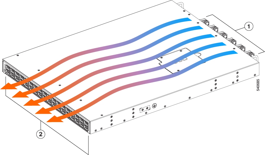
Fans intake air, blow it through the chassis, and exhausts heated air through the port side. Make sure to install fans correctly for proper airflow.
|
1 |
Fan side, intake air |
|
2 |
Port side, exhaust air |
Removing a Fan Module
 Warning |
The fans might still be turning when you remove the fan assembly from the chassis. Keep fingers, screwdrivers, and other objects away from the openings in the fan assembly's housing. |
Procedure
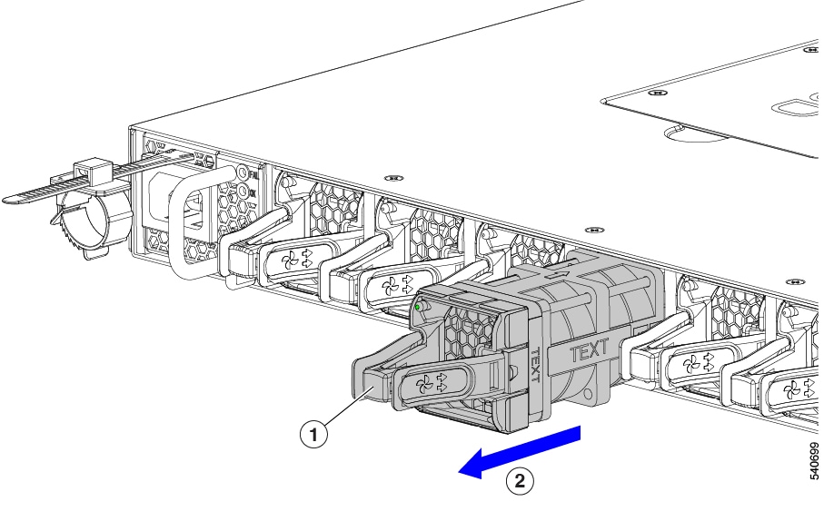
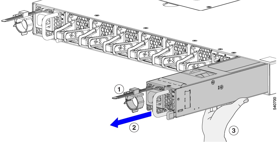
| Step 1 |
On the fan module that you are removing, press the two sides of the fan module handle next to where it connects to the fan module and pull on the handles enough to unseat it from its connectors. |
||
| Step 2 |
Holding the handle, pull the module out of the chassis.
|
Installing a Fan Module
Before you begin
-
A fan slot must be open and ready for the new fan module to be installed.
-
You must have a new fan module on hand and ready to install within one minute of removing the original fan module if the fabric interconnect is operating.
-
The new fan module must have the same airflow direction as the other fan and power supply modules installed in the fabric interconnect.
Procedure
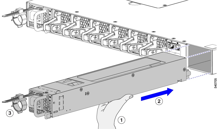
| Step 1 |
Holding the fan module by its handle, align the back of the fan module (the side with the electrical connectors) to the open fan slot in the chassis. |
| Step 2 |
Slide the fan module into the slot until it clicks in place.
|
| Step 3 |
Verify that the Status LED turns on and becomes green. |


 Feedback