- Enterprise Network Overview
- Hierarchical Model
- Enterprise Access Layer
- Enterprise Distribution Layer
- Enterprise Core Layer
- Enterprise Endpoints
- Cisco DNA Center
- Cisco DNA Center Appliance
- Shared Services
- SD-Access Overview
- SD-Access Roles Summary
- SD-Access Transit Networks
- Enterprise Security Overview
- Enterprise QoS Overview
- Enterprise Wireless Network
- Extended Enterprise Network
- Extended Enterprise Security Policy Design
- The Rationale for Securing the Extended Enterprise Network
- Design the Security Policy in Extended Enterprise Network
- Security Design Considerations for Non-Fabric Deployments
- Security Design Considerations for SD-Access Deployments
- Security Implementation Differences Between Fabric and Non-Fabric Deployments
- Managing Device Software Images
- Extended Enterprise QoS Policy Design
- Extended Enterprise Network Dataflows for Non-Fabric Deployments
- Extended Enterprise Network Dataflows for SD-Access Deployments
- Extended Enterprise High Availability
- Extended Enterprise Scale and Dimensioning
Cisco Extended Enterprise non-fabric and SD-Access fabric Design Guide
Extended Enterprise Introduction
Network administrators are being asked to extend network connectivity beyond the carpeted space of an enterprise to connect and manage networks and end devices deployed in the outdoor enterprise spaces. These outdoor enterprise spaces are referred to as Extended Enterprise (EE). An enterprise extension spreads its information technology (IT) and operational technology (OT) networks to its production, storage, distribution, and outdoor facilities. Extended Enterprise extends network connectivity, security policy, and management to the outdoors, warehouses, and distribution centers of an enterprise—with the same network management system—offering automation, policies, and assurance. The Cisco® Digital Network Architecture (Cisco DNA) is an architecture based on automation and analytics to deliver policy end-to-end at scale. Cisco DNA enables customers to capture business intent and activate it network wide in the campus and in non-carpeted spaces where the operations occur. Thus, Extended Enterprise helps transform business by extending Cisco’s intent-based networking to the Internet of Things (IoT) Edge.
Extended Enterprise CVD
Cisco Validated Design (CVD) serves as a bridge between network products and their realization into an end customer solution. CVD consists of a design guide with a validated design and an implementation guide covering a validated solution with end-to-end setup, configuration, and operation details.
The Extended Enterprise Cisco Validated Design, which is documented in this design guide, provides a design foundation for incorporating a broad set of technologies, features, and applications to help customers extend the enterprise IT services to outdoor spaces including production, storage, and distribution facilities.
This CVD outlines the steps to accomplish business goals by digitizing the operations in the outdoor spaces of an enterprise. It includes design guidance for Extended Enterprise use cases with the customer's existing Cisco DNA Center™ using the Cisco industrial networking portfolio. The design proposed in this guide has been comprehensively tested by Cisco engineers to help ensure a faster, more reliable, and fully predictable deployment.
Scope and Audience
Extended Enterprise design guide provides an overview of the requirements driving the evolution of Extended Enterprise network designs followed by a discussion of the latest technologies and designs that are available for building an extended network to address those requirements. It is a companion to the associated Design and Deployment Guides (DDGs) for enterprise networks, which provide configurations explaining how to deploy the most common implementations of the designs as described in this guide. The intended audience are technical decision makers who want to understand the Cisco Extended Enterprise offerings, the technology options available, and the leading practices to design the best network for the needs of an extended enterprise.
The design guide incorporates:
■![]() A reference design for extending the enterprise network with the Cisco DNA Center to outdoor spaces.
A reference design for extending the enterprise network with the Cisco DNA Center to outdoor spaces.
■![]() Design of a centralized policy matrix using the Cisco DNA Center and the Identity Service Engine (ISE).
Design of a centralized policy matrix using the Cisco DNA Center and the Identity Service Engine (ISE).
■![]() Design and implementation of security segmentation for Extended Enterprise endpoint points such as cameras, phones, laptops, and others.
Design and implementation of security segmentation for Extended Enterprise endpoint points such as cameras, phones, laptops, and others.
■![]() Guidance on how to deploy and manage extended nodes (EN), policy extended nodes (PEN), and industrial wireless devices using the Cisco DNA Center.
Guidance on how to deploy and manage extended nodes (EN), policy extended nodes (PEN), and industrial wireless devices using the Cisco DNA Center.
For the associated deployment guides, related design guides, and white papers, see the following pages and Appendix A—Related Documentation:
■![]() Cisco Enterprise Networking design guides at the following URL:
Cisco Enterprise Networking design guides at the following URL:
–![]() https://www.cisco.com/go/designzone
https://www.cisco.com/go/designzone
■![]() Cisco IoT Solutions design guides at the following URL:
Cisco IoT Solutions design guides at the following URL:
–![]() https://www.cisco.com/go/iotcvd
https://www.cisco.com/go/iotcvd
■![]() Cisco Extended Enterprise Solutions overview, design and implementation guides at the following URL:
Cisco Extended Enterprise Solutions overview, design and implementation guides at the following URL:
Scope of CVD Release 2.1
This 2.1 Extended Enterprise Design Guide provides network architecture and design guidance for the planning and subsequent implementation of an Extended Enterprise solution. In addition to this design guide, the Extended Enterprise Implementation Guide provides specific implementation and configuration guidance.
This Release 2.1 design guide supersedes and replaces the Release 2.0 design guide.
New Capabilities in EE Release 2.1
■![]() Inclusion of dynamic endpoint authentication by extended nodes and inclusion of policy extended nodes
Inclusion of dynamic endpoint authentication by extended nodes and inclusion of policy extended nodes
■![]() Inclusion of embedded WLC in the Extended Enterprise fabric wireless network
Inclusion of embedded WLC in the Extended Enterprise fabric wireless network
■![]() Inclusion of ruggedized outdoor Access Points (AP), IW6300, into Extended Enterprise Wi-Fi network
Inclusion of ruggedized outdoor Access Points (AP), IW6300, into Extended Enterprise Wi-Fi network
References
To learn more about Extended Enterprise solutions, see:
The Value of the Extended Enterprise CVD to an Organization
As your organization grows, you must plan how to extend the enterprise network infrastructure to support the network requirements of non-carpeted spaces. Planning, testing, and implementing various components and shared services for an extended network poses a large challenge for organizations. In contrast, by using the Extended Enterprise CVD's modular approach that tests and validates the foundation infrastructure, security, automation, assurance, and shared services, organizations can reduce costs, risks, and operational issues and increase deployment speed.
An organization can benefit in the following ways by deploying the Extended Enterprise CVD:
■![]() Summarized and simplified design choices for accelerating design, deployment, and operation of the extended networks.
Summarized and simplified design choices for accelerating design, deployment, and operation of the extended networks.
■![]() Simplicity through a single pane of glass (SPOG) for managing carpeted and non-carpeted spaces, including design, policy enforcement, provisioning, and assurance for all network devices.
Simplicity through a single pane of glass (SPOG) for managing carpeted and non-carpeted spaces, including design, policy enforcement, provisioning, and assurance for all network devices.
■![]() Intent-based policies for IoT end points.
Intent-based policies for IoT end points.
■![]() Reduced cost of zero touch deployment (ZTD) through Plug and Play (PnP) for provisioning Industrial Ethernet (IE) switches and outdoor wireless access points (APs).
Reduced cost of zero touch deployment (ZTD) through Plug and Play (PnP) for provisioning Industrial Ethernet (IE) switches and outdoor wireless access points (APs).
■![]() Scalability provided by intent-based networking, assurance, guided remediation, and troubleshooting.
Scalability provided by intent-based networking, assurance, guided remediation, and troubleshooting.
■![]() High availability and reliability in non-carpeted spaces for resilient operations.
High availability and reliability in non-carpeted spaces for resilient operations.
Business Overview
Introduction to Cisco Digital Network Architecture
The top-of-mind issue in IT organizations today is digital transformation. The enterprise network is at the heart of every digital transformation. Most enterprises have thousands of users, thousands of applications, and often tens of thousands of network-enabled devices. Global IP traffic is projected to nearly triple from 2017 to 2022; additionally, 10 billion more Internet of Things (IoT) devices are expected to come online within the same time frame (according to Cisco Visual Networking Index™ forecasts1).
Each year various new devices in different form factors with increased capabilities and intelligence are introduced and adopted in the market. A growing number of machine-to-machine (M2M) applications, such as smart meters, video surveillance, healthcare monitoring, transportation, and package or asset tracking, are providing a major contribution to the growth of devices and connections. By 2022, M2M connections will be 51 percent of the total devices (according to Cisco Visual Networking Index forecasts).
Manual management of network operations is becoming increasingly untenable for IT departments, a challenge that is exacerbated by the myriad inconsistent and incompatible hardware and software systems and devices in the enterprise. In contrast, an intent-based, closed-loop architecture that includes automation and analytics platforms significantly frees up IT time and resources, and allows them to be reallocated to driving strategic projects and digital transformation. Cisco DNA Center is the platform that introduces automation and analytics into the enterprise network. Cisco DNA Center is a single pane of glass for designing a network, provisioning the network, administering policy for the network, and assuring the network.
The primary purpose of the automation platform in Cisco DNA Center is to “talk” to the network—in other words, to translate the expressed business intent into optimal platform-specific configurations on the network devices. In a complementary manner, the primary role of the analytics platform is to “listen” to the network, specifically to gather, correlate, and make sense of all the network telemetry generated by network devices, in order to correlate this data with the expressed business intent.
The Cisco Digital Network Architecture provides a road map to digitization and a path to realize immediate benefits of network automation, assurance, and security. Cisco Software-Defined Access (SD-Access) is the Cisco DNA evolution from traditional campus LAN designs to networks that directly implement the intent of an organization. SD-Access is enabled with an application package that runs as part of the Cisco DNA Center software for designing, provisioning, applying the policy, and facilitating the creation of an intelligent campus wired and wireless network with assurance.
Fabric technology, an integral part of SD-Access, enables wired and wireless campus networks with programmable overlays and easy-to-deploy network virtualization, permitting a physical network to host one or more logical networks as required to meet the design intent. In addition to network virtualization, fabric technology in the campus network enhances control of communications, providing software-defined segmentation and policy enforcement based on user identity and group membership.
SD-Access support for extended nodes and policy extended nodes is about extending the enterprise network to provide more connectivity to non-carpeted spaces of an enterprise. The products for extending the enterprise network are different, but the processes and techniques to build it out are the same.
Extended Enterprise Overview
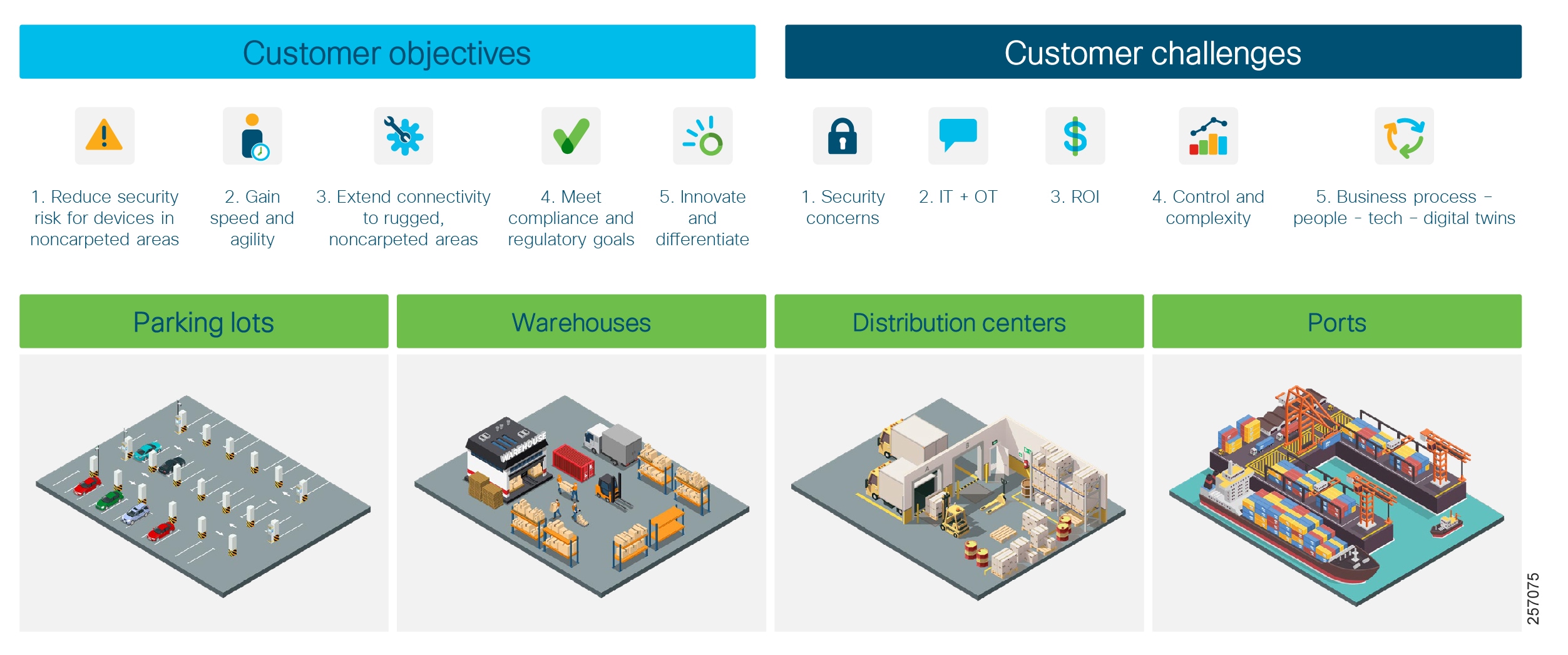
The Extended Enterprise is where business operations happen—outdoor and non-carpeted spaces such as distribution centers, warehouses, ports, or campus parking lots. Enterprises are looking to innovate and differentiate their offerings by digitizing their operations beyond the traditional carpeted spaces. However, the initiatives on digitizing the operations require network connectivity to be extended beyond the traditional air-conditioned spaces to connect and manage IoT devices, as well as deploying traditional enterprise end devices in outdoor and non-carpeted environments.
Customers require ruggedized Ethernet switches, routers, and outdoor wireless APs to extend network connectivity to non-carpeted spaces because of the harsh environments in outdoor spaces. In addition, security concerns for extended networks should be addressed with consistent network policies. Customers require speed with agility to deploy and manage networks in non-carpeted spaces while meeting the required compliance and regulatory goals, as illustrated in Figure 1.
With digitization, enterprises are challenged to improve operational efficiency, deliver new service offerings, and increase customer satisfaction. Delivering these business outcomes require a new, intent-based approach to networking in order to manage the challenges of scale and security faced by the enterprise.
Figure 1 Extended Enterprise Objectives and Challenges
By connecting the Extended Enterprise to your core IT managed networks, you can:
■![]() Unleash the power of data from the edge to gain operational insights and improve processes and systems
Unleash the power of data from the edge to gain operational insights and improve processes and systems
■![]() Enable new digital experiences for your customers and increase customer satisfaction
Enable new digital experiences for your customers and increase customer satisfaction
■![]() Generate new incremental revenue for your business by digitizing your extended enterprise
Generate new incremental revenue for your business by digitizing your extended enterprise
■![]() Manage the entire enterprise network centrally and reduce operating expenses (OpEx)
Manage the entire enterprise network centrally and reduce operating expenses (OpEx)
■![]() Simplify, secure, and control IT-run industrial Extended Enterprise environments
Simplify, secure, and control IT-run industrial Extended Enterprise environments
Note: The Extended Enterprise CVD focuses on extending the enterprise network to outdoor spaces for deploying various use cases and management by IT as a single pane of glass. The vertical use cases specific to each portfolio are beyond the scope of this guide.
Extended Enterprise Network Requirements
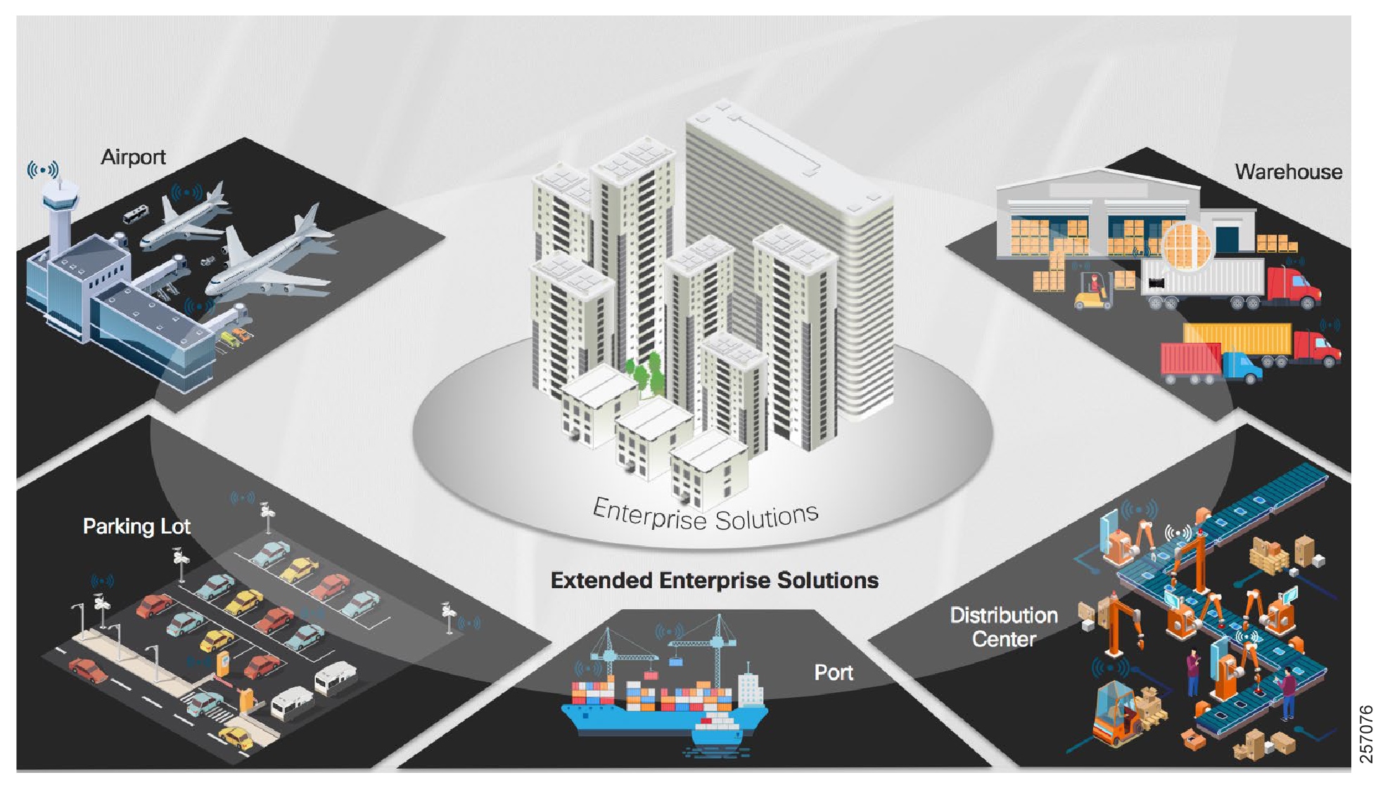
Many enterprises have warehouses, campus/stadium, parking lots, and distribution centers; typically, more than one. Figure 2 shows some of the extended enterprise use cases. Because of dust, heat, cold, dampness, and humidity, these outdoor facilities require ruggedized networking products. Enterprises want to replicate operations as much as possible to save on capital expenditures and operational costs.
Figure 2 Extended Enterprise Use Cases
With the explosive growth in IoT and industrial devices connecting to the core network, combined with the need to secure against threats and secure network access, IT must oversee, manage, and secure extended spaces, and ensure business integrity. Therefore, network teams are being asked to extend network connectivity beyond the air-conditioned spaces more and more in order to connect and manage IoT devices as well as traditional enterprise end devices being deployed in outdoor or extreme-temperature environments. The overall goal is to drive efficiency and reduce OpEx in the non-carpeted spaces with industrial networking.
Outdoor facility networking requirements need IT to be able to quickly provision devices and services, manage the network device inventory, manage the software versions of the network devices, and do it all securely.
Most enterprises also have a need to enable outdoor connectivity to campus parking lots in adverse weather conditions for assets such as IP cameras, video encoders, and Wi-Fi APs.
Enterprises that have distribution centers need reliable network operation without air conditioning costs. Operational efficiency of the connected equipment is of key interest to distribution centers and IT executives. Consolidation of warehouse and distribution center networks into one centrally-managed network greatly simplifies Extended Enterprise networks managed by IT through the Cisco DNA Center and SD-Access fabric. The Cisco DNA Center can provide a SPOG for managing enterprise and Extended Enterprise networks.
This Extended Enterprise Design Guide addresses the network requirements described below.
Flexible Industrial Ethernet Network Foundation for Harsh Environments in Non-Carpeted Spaces
Extended enterprise environments require network devices to operate in very hot (+70°C), very cold (-40°C), and dusty environments. Extended enterprise network devices need to be hardened for vibration, shock and surge, and noise immunity while adhering to overall IT network design, compliance, and performance requirements.
Extended enterprise deployments in outdoor spaces, warehouses, and distribution centers require high-speed gigabit Ethernet connectivity in a compact form factor modular design, which is flexible for rapid expansion, bandwidth, and capacity planning to grow with the needs of operations.
The industrial Ethernet network in non-carpeted spaces must comply with stringent industry standards for electromagnetic emissions, immunity, and safety.
Cisco is the leading manufacturer of managed Industrial Ethernet switches at both Layer 2 and Layer 3, including >1 GB Ethernet ports. Cisco Industrial Ethernet switches support industrial characteristics such as DIN rail/rack mount/ embedded form factors, extended operating temperatures, passive cooling, redundant components, industrial connectors, higher IP rating and several industrial network protocols. The switches also offer copper, fiber, and Power over Ethernet (PoE) port options. The platform provides the flexibility to adapt your growing network connectivity needs and helps to future-proof your investments.
Cisco Industrial Ethernet switches can be managed through Cisco DNA Center platform, enabling IT to extend Intent-Based Networking and single security policy framework from the data center, through the enterprise network, to the ruggedized network.
Extend Secure Connectivity to Outdoor Non-Carpeted Spaces for Users, Traditional IT Endpoints, and Things
Enterprises have an ever-increasing requirement to securely connect IoT endpoints (things) in outdoor environments. The Cisco IE switching products are a great example of providing networking connectivity outside the wiring closet. These devices are deployed outdoors, in the ceiling, or in roadside cabinets. The extended access network should have the ability to support high-density industrial PoE/PoE+ providing in-line power for devices such as IP cameras and phones, badge readers, and Wireless APs.
Most Extended Enterprise environments need IP video surveillance for security, APs for mobility, IP phones, desktop PC access, and networked printers—the same types of networked end devices that you would find within an air-conditioned office building.
Capture and Translate Business Intent into Network Policies and Consistently Enforce the Policies across the Entire Network
An ever-growing number of cyber-attacks that are carried out by individuals, organized syndicates, and state-sponsored hackers are launched daily against organizations of all types. Whether for financial gain through acquiring credit card data, extortion through ransomware, identity theft, or disruption of services through access to personal data, these attacks are growing in frequency and sophistication. The Cisco 2017 Security Capabilities Benchmark Study found that nearly a quarter of the organizations that have suffered an attack lost business opportunities as a result. Four in ten said those losses are substantial. One in five organizations lost customers due to an attack, and nearly 30 percent lost revenue. Furthermore, with the ever-growing availability of open-source code bases and tools, these attacks no longer require a high level of skill, enabling them to be launched by less sophisticated threat actors. To understand how to defend against today's critical threats, please refer to the Cisco Cybersecurity 2019 threat report.
Because network entry points are common targets for security attacks, hardening the security of the network devices is essential. Intent-based networking (IBN) enables conventional practices that require the alignment of manually-derived individual network-element configurations to be replaced by controller-led and policy-based abstractions that easily enable operators to express intent (desired outcome) and subsequently validate that the network is doing what they asked of it. The controllers, which provide the automation and controls that make up the IBN, reduce risk by ensuring that security policies are being applied consistently across the extended network, and help ensure that policies are compliant with Extended Enterprise business requirements. They capture and translate business intent into network policies and activate them across the infrastructure.
Operations intent-based groupings provide consistent policy and access independent of network topology in carpeted and non-carpeted spaces. Creating group-based policies leveraging attributes such as device type and location provides a much easier and scalable way to manage security policies for access control across the extended enterprise. Security Group Tags (SGTs) that are assigned from group-based policies can provide micro-segmentation within a virtual network.
Simple, Centralized Network Management across Carpeted and Non-Carpeted Spaces
Managing network operations manually is becoming increasingly untenable for IT departments, a challenge that is exacerbated by the myriad inconsistent and incompatible hardware and software systems and devices in the enterprise.
Adding more devices to the extended network increases the management complexity. To drive simplicity, it is important for enterprises to have a SPOG for designing, provisioning, and administering policies, and ensuring the network consistently across carpeted and non-carpeted spaces. The goal is for network engineers to see everything going on in the network, everywhere in the world, from one interface.
To drive business growth and innovation, a complete network management system that is centralized across carpeted and non-carpeted spaces is required. Customers need a network management system that can automate the deployment, connectivity, and lifecycle of your infrastructure and proactively maintain the quality and security of your applications so that IT staff can focus on networking projects that enhance your core business.
Reduce Day Zero Deployment Time of Networks in Non-Carpeted Spaces
Many Extended Enterprise environments do not have an on-site IT network engineer and the extended network must be managed remotely. IT staff need to be able to quickly deploy new devices and new services. Time is critical and expensive since the installer is likely an hourly contractor or has to travel from the corporate office to be on site.
An extended network should automatically remotely provision and onboard new network devices with minimal network administrator and field personnel involvement. A workflow should define a network device provisioning process that includes a series of actions such as installing a software image, applying a device configuration, renumbering a switch stack, or specifying a switch stack license.
The Cisco DNA Center provides the PnP feature for zero-touch network deployment in non-carpeted spaces. With PnP, you should be able to ship new industrial networking devices directly to the warehouse or a distribution center where a local person will power it up. The switch will automatically connect to the Cisco DNA Center to retrieve the correct code based on its serial number. PnP can significantly reduce the time for provisioning the extended network and for spending on upgrades by automating the steps.
Compliance to Latest Security Patches of Industrial Networking
It is expected that code written today will have vulnerabilities in the future. For example, the Heartbleed Bug vulnerability, which is a vulnerability in OpenSSL that puts millions of devices at risk because they use common source code, was discovered well after many devices had adopted the OpenSSL library as a common cryptographic library. The Heartbleed Bug vulnerability was not just meant for Web servers, but also IoT devices became a victim of this vulnerability. Attacks exploiting security vulnerabilities in IoT devices are not uncommon. Reports of security attacks on IoT devices that exploit the vulnerabilities of the device frequently occur. Using default passwords and poor patching are often the common culprits.
Network administrators are always challenged when it comes to upgrading their network, whether it is planned or ad hoc, in order to remediate a security vulnerability. As Extended Enterprise networks become more and more complex, it becomes even harder to manage the software versions and deploy the new security patches when they become available.
To determine whether software image standards comply with the deployed devices, it is imperative that device auditing is automated and flag devices that are not compliant with standardized software image updates. Patching provides small updates to react quickly to security fixes. The Cisco DNA Center simplifies the version management and routine deployment of software updates to your network devices by helping customers plan, schedule, download, monitor, and standardize software image updates.
Secure Outdoor Wireless Connectivity in Non-Carpeted Spaces
Extended enterprise networks require rugged outdoor Wi-Fi coverage for their outdoor clients. Wireless video cameras monitor security. In large installations, the roaming functionality provided by multiple APs enables wireless users to move freely throughout the facility while maintaining uninterrupted access to the network. The security requirements described above should be consistent for wired Ethernet or wireless LAN.
With the latest 802.11ac Wave 2 technology, transmitting data at speeds beyond 1Gbps can accommodate growth in wireless usage in outdoor spaces. One key part of 802.11ac Wave 2 technology that can help keep extended networks ahead of the capacity crunch is Multi-user multiple-input and multiple-output (MU-MIMO). MU-MIMO allows an access point to transmit to multiple clients at the same time instead of sending data to a single client at a time. These parallel transmissions improve RF efficiency when client devices also support 802.11ac Wave 2.
Cisco outdoor APs can be deployed as traditional access points or wireless mesh access points. Cisco Flexible Antenna-Port technology uses software that is configurable for either single- or dual-band antennas. It allows customers to use the same antenna ports for either dual-band antennas to reduce footprint or single-band antennas to optimize radio coverage.
Simplify Deployment of QoS across the Extended Network
Extended networks can have a variety of business needs for Quality of Service (QoS). A safety and security operations business may want to ensure a high-quality images for video cameras in the campus parking lots for video surveillance. A distribution center may want to guarantee voice quality to meet enterprise standards.
The principle goal of a QoS policy for an extended network is to express the strategic QoS policy with maximum fidelity and to generate platform-specific configurations. The Cisco DNA Center can simplify the deployment of QoS across the extended enterprise.
Network Assurance—Visibility and Analytics on the Health of Industrial Network Devices
As networks grow in complexity, research show that network IT spends four times more time collecting the data than analyzing the problem. In a world of device explosion and extended networks, this problem will only get worse. The traditional response to onboarding incidents involves many manual steps, such as checking user credentials and DHCP issues, and radio channel analysis, all of which adds to a high incident response time.
It is imperative an extended network has onboarding analytics across the entire network—both wired and wireless. Cisco DNA Center Assurance uses anomaly-driven telemetry from 240+ real-time events coming from the wireless and wired infrastructure on client onboarding that helps to evaluates the time to connect and possible stages for the delay. Any delays in onboarding will be spotted and flagged by the Cisco DNA Center before the user has a chance to report the problem.
Guided Remediation and Troubleshooting of Issues in the Extended Network
A very common challenge facing IT is isolating problems; in other words, IT personnel are faced with finding the needle in a haystack. Further, unlike wired networks with their relative predictability, wireless networks are easily impacted by more dynamic and fluctuating variables (such as Received Signal Strength Indicators and Signal-to-Noise Ratios). As such, the challenge is exacerbated and can be more aptly described as trying to find a randomly appearing and disappearing needle within a haystack! Issues come and go as more rogue devices come online. And if IT cannot replicate such transient and fluctuating Wi-Fi issues, they cannot resolve them.
To guide remediation to a network issue, it is important to have a holistic view of users, clients, applications, and the network with full context of the interactions between these elements. Furthermore, troubleshooting is not limited to currently occurring issues, but Cisco DNA Center allows operators to “go back in time” via a time-series database of all measured data points to diagnose and root-cause issues that have occurred in the past.
Cisco DNA Center Assurance provides a 14-day look back, giving the full contextual network data and interrelationships and eliminating the need to replicate the issue in order to identify and resolve a problem. All information on the user or the network device changes to the selected time.
Extend Shared Services to Extended Networks in Non-Carpeted Spaces
Most extended network deployments require access to shared services in the form of identity services, Dynamic Host Configuration Protocol (DHCP), Domain Name System (DNS), IP Address Management, IP voice/video collaboration services, application servers, and data center applications. It is important that these shared services are designed correctly in order to preserve the isolation between different virtual networks sharing those services. Most deployments require shared services across all virtual networks and other inter-virtual network communication.
High Availability, Reliability, and Scale of Extended Networks to Meet Operational Needs
Most Extended Enterprise network deployments have to cater to the needs of business-critical operations. Therefore, extended network designs should enable end-to-end redundancy and high availability. The design should extend geographical scalability where longer-distance connectivity is required.
Example Use Case—Secure Connectivity for Campus Parking Lots
Many enterprise campuses have a number of parking lots to cater to the needs of their employees and guests. Campus parking lots are typically monitored by safety and security operations teams responsible for theft prevention and for ensuring safety of the employees and the guests. Digitizing the campus parking lots can help improve the overall experience of the employees such as a mobile application tracking a free electric vehicle charging station near a campus building. In addition, enabling secure outdoor wireless connectivity in the campus parking lots is desirable for business collaboration.
The safety and security operations would like to have IP video surveillance cameras installed in the parking lots to ensure the safety of employees and the guests entering or leaving the parking lot. Live streaming and video retention to comply with local policies is critical for the safety and security operations agents to monitor from remote locations. Appropriate QoS policies for campus or WAN network bandwidth allocation is needed for live video monitoring by remote agents.
How can we address such network requirements in outdoor spaces where network devices need to be able to work in ruggedized spaces, connecting PoE-powered end devices such as IP cameras, phones, wireless access points, sensors, and more? The network devices should be hardened to withstand harsh environments, temperature ranges (-40°C to +75°C), vibration, shock, surge, and electrical noise. More importantly, the network devices should comply to the safety standards and certifications with high Mean Time Between Failures (MTBF).
The Cisco IE switches, routers, and outdoor wireless APs have been designed specifically to withstand the harshest industrial environments in a compact, form-factor, modular switch that is purpose-built for a wide variety of Extended Enterprise applications, such as campus parking lot environments. The IE switches provide bandwidth and capacity to grow with a customer's networking needs: full gigabit Ethernet interfaces to connect high-speed wireless APs and high-definition (HD) IP cameras.
An employee or guest's mobile device or a parking lot IoT sensor, when compromised by malware, may change network communication behavior to propagate and infect other endpoints. Cisco ISE and Cisco SD-Access can address the need for complete isolation between the IoT sensors, traditional IT endpoints such as IP cameras, and the enterprise network by using macro segmentation, and adding devices into different overlay networks, thus enabling the isolation.
Flexible policy creation allows the ability to have groups of device types and user roles to restricted communication within a group or amongst groups. By extending the secure connectivity to campus parking lots, IT should be able to leverage the existing investments in their campus network for non-carpeted spaces.
The primary solution components are Cisco IE switches, outdoor APs, Cisco DNA Center, Cisco ISE, and the Cisco DNA Assurance Engine. The Cisco DNA Center is the primary application for designing, defining policy, and provisioning the network infrastructure—a SPOG across the carpeted and non-carpeted spaces of an enterprise. The ISE provides the security behind the solution. The Cisco DNA Assurance Engine gives insight into network and user performance.
Deploying the intended outcomes for the needs of the Extended Enterprise operations is simplified using the automation capabilities built into the Cisco DNA Center, and those simplifications span the wired and wireless domains.
System Design
Extending the enterprise is about leveraging already existing campus networks and adding connectivity to outdoor and non-carpeted spaces using the Cisco industrial networking portfolio. The design addresses both extended enterprise SD-Access as well as non-fabric deployments. Most concepts discussed in the design apply to both. Differences and specific details will be highlighted when applicable.
This chapter, which discusses the end-to-end system design starting with an overview of the enterprise network and followed by a detailed design for the Extended Enterprise network, includes the following major topics:
■![]() Extended Enterprise Security Policy Design
Extended Enterprise Security Policy Design
■![]() Extended Enterprise QoS Policy Design
Extended Enterprise QoS Policy Design
■![]() Extended Enterprise Network Dataflows for Non-Fabric Deployments
Extended Enterprise Network Dataflows for Non-Fabric Deployments
■![]() Extended Enterprise Network Dataflows for SD-Access Deployments
Extended Enterprise Network Dataflows for SD-Access Deployments
■![]() Extended Enterprise High Availability
Extended Enterprise High Availability
■![]() Extended Enterprise Scale and Dimensioning
Extended Enterprise Scale and Dimensioning
Enterprise Network Overview
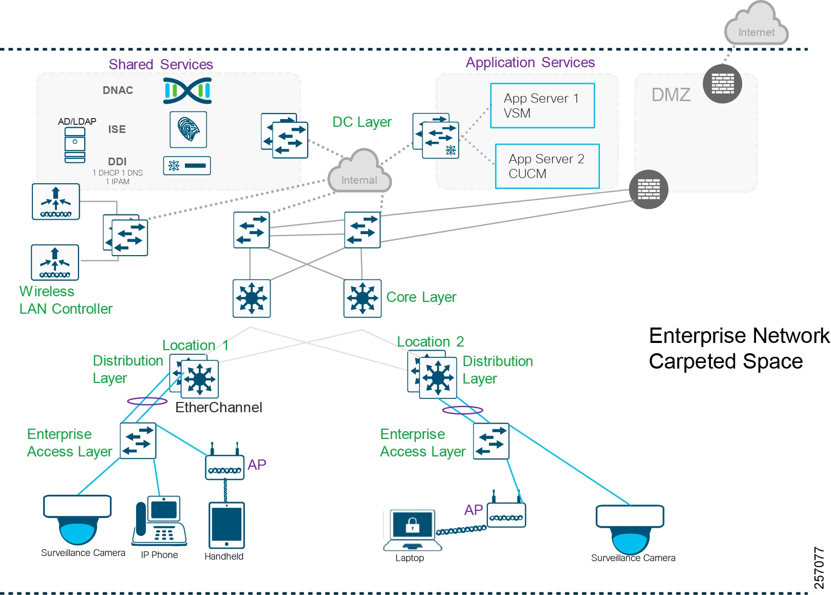
The enterprise could be a geographically-distributed organization spread across multiple sites and campuses. The overall enterprise network is managed by the Cisco DNA Center. Wireless and wired connectivity is provided across the enterprise. Several types of hosts or endpoints such as video surveillance cameras, Wi-Fi clients, IP phones, and video terminals are connected to the enterprise network for different services. The application services are centrally hosted and have restricted access to authorized clients. Enterprise-wide shared services such as the DHCP server, IP Address Management (IPAM), DNS, and ISE are hosted in the data center along with the Cisco DNA Center. Enterprise internet connectivity is protected by the firewall. Internet access is available across the organization. The Cisco DNA Center requires internet access for regular cloud updates.
The enterprise network, depending on the size and its needs, can be a two-layered or three-layered architecture. The design considerations and design details for the Extended Enterprise apply equally well to both architectures. For illustration purposes, a three-layered architecture, as shown in Figure 3, is considered to be the Enterprise Network Architecture. The three layers are the core, distribution, and access. The following section describes a high-level overview of these hierarchical layers and respective roles.
Figure 3 Enterprise Network Design
Hierarchical Model
The hierarchical network design model breaks the design into modular layers. Each layer implements specific functions, thus helping simplify network design, deployment, and management and also making the network scalable. Modular structuring of the network also improves scalability and facilitates resiliency through improved fault isolation. Cisco Enterprise Network Design CVDs cover these architectures (please see Appendix A—Related Documentation).
The three-layered architecture consists of the following:
■![]() Access Layer—Provides endpoints and users direct access to the network.
Access Layer—Provides endpoints and users direct access to the network.
■![]() Distribution Layer—Aggregates access layers and provides connectivity to services.
Distribution Layer—Aggregates access layers and provides connectivity to services.
■![]() Core Layer—Provides connectivity between distribution layers for large LAN environments. Capacity, density, and features are the primary differences that drive what platform to select.
Core Layer—Provides connectivity between distribution layers for large LAN environments. Capacity, density, and features are the primary differences that drive what platform to select.
Enterprise Access Layer
The access layer, which is placed at a close proximity, provides connectivity to user devices and clients that are connected to the network. The access layer provides both wired and wireless connectivity and contains features and services that ensure security and resiliency for the entire network. Typically incorporating Layer 2 switches, it provides different functionalities that include:
■![]() Layer 2 connectivity—fiber or copper and wireless to endpoints (e.g., laptops, cameras, and IP phones)
Layer 2 connectivity—fiber or copper and wireless to endpoints (e.g., laptops, cameras, and IP phones)
■![]() Can provide PoE power to wired endpoints
Can provide PoE power to wired endpoints
■![]() Enforces security by end user authentication and security policy enforcement
Enforces security by end user authentication and security policy enforcement
Enterprise Distribution Layer
The distribution layer has several important services. It aggregates access layers and provides connectivity services. It aggregates traffic from several access layer switches and provides uniform transportation. The important features provided by distribution layer devices include:
■![]() Layer 3 connectivity to the core layer and Layer 2 into the access
Layer 3 connectivity to the core layer and Layer 2 into the access
■![]() Aggregation of access layer traffic and provide connectivity services
Aggregation of access layer traffic and provide connectivity services
■![]() Routing between LAN and VLANs
Routing between LAN and VLANs
■![]() Route aggregation and summarization
Route aggregation and summarization
■![]() Policy-based security and QoS
Policy-based security and QoS
■![]() Scalability, fault domain isolation, high availability, and resiliency
Scalability, fault domain isolation, high availability, and resiliency
■![]() Typically, a Layer 3 router or a Layer 3-capable switch is used
Typically, a Layer 3 router or a Layer 3-capable switch is used
Enterprise Core Layer
A third layer serving as the backbone and central point of the network is often needed while catering to a large distributed network spread across multiple geographically-dispersed buildings. Having a distribution layer switch in each of the buildings helps to reduce costly fiber runs. As networks grow beyond three distribution layer switches, organizations should use a core layer to optimize the design.
The key value-adds and features of the core layer include:
■![]() Uninterrupted connectivity to the distribution layer
Uninterrupted connectivity to the distribution layer
■![]() Provides site-wide redundancy, fault tolerance, resiliency, and reliability having Layer 3 connectivity to and from the core layer
Provides site-wide redundancy, fault tolerance, resiliency, and reliability having Layer 3 connectivity to and from the core layer
■![]() Provides high-speed switching (in other words, fast transport) to support a large-scale network
Provides high-speed switching (in other words, fast transport) to support a large-scale network
■![]() Very low latency, avoiding CPU-intensive packet manipulations
Very low latency, avoiding CPU-intensive packet manipulations
Enterprise Endpoints
The devices that connect to the enterprise access switch are called endpoints. Endpoints may be either wired clients that directly connect to the access switch node or wireless clients attached to an AP. Endpoints could be a security camera, IP phone, user laptop, tablet, or mobile phone connected to the network. Endpoints are increasing due to workforce mobility, which helps users to be less tethered to the desk, but an ever-increasing risk of endpoints loaded with insecure applications, with consistent exposure to malware across Internet protocols, exists. Therefore, endpoint security consisting of authentication, posturing, profiling, and authorization is becoming critical.
Cisco DNA Center
The Cisco DNA Center is an open and extensible management platform with a SPOG solution for the entire enterprise to realize intent-based networking that provides network automation, assurance, and orchestration. It enables management of a large-scale network of thousands of devices. It can configure and provision thousands of network devices across an enterprise in minutes instead of hours.
The major priorities for any large enterprise network are security, service assurance, automation, and visibility. These requirements are to be guided by enterprise policy or intent. The Cisco DNA Center enables intent based network management by automatically translating the policies to individual device specific commands and executes them automatically in the entire network scope,
The Cisco DNA Center has the following operations workflow areas:
■![]() Design—Configures device global settings, network site profiles for physical device inventory, DNS, DHCP, IP addressing, software image inventory, network templates, and wireless design.
Design—Configures device global settings, network site profiles for physical device inventory, DNS, DHCP, IP addressing, software image inventory, network templates, and wireless design.
■![]() Policy—Defines business intent for provisioning into the network, including creation of virtual networks, security policies, and application policies.
Policy—Defines business intent for provisioning into the network, including creation of virtual networks, security policies, and application policies.
■![]() Provision—Provisions devices for management and PnP, has device inventory. Provides tools to provision fabric infrastructure and onboard devices.
Provision—Provisions devices for management and PnP, has device inventory. Provides tools to provision fabric infrastructure and onboard devices.
■![]() Assurance—Enables proactive monitoring and insights to confirm user experience meets configured intent, using network, client, and application health dashboards, issue management, and sensor-driven testing.
Assurance—Enables proactive monitoring and insights to confirm user experience meets configured intent, using network, client, and application health dashboards, issue management, and sensor-driven testing.
■![]() Platform—Allows system integration with third-party systems.
Platform—Allows system integration with third-party systems.
Cisco DNA Center Appliance
The Cisco DNA Center software application package is designed to run on the Cisco DNA Center Appliance. When the Cisco DNA Center Appliance becomes unavailable, the network still functions, but automated provisioning and network monitoring capabilities are lost. For high availability, it is recommended to configure three Cisco DNA Center Appliances to form a three-node cluster. The Cisco DNA Center cluster is accessed using a single GUI interface hosted on a virtual IP address, which is serviced by the resilient nodes within the cluster. Multi-node clusters inherently can perform service or load distribution, database, and security replication. Clusters will survive loss of a single node.
Note: The first generation M4-based appliances are end-of-life declared; second generation M5-based appliances should be used.
■![]() https://www.cisco.com/c/en/us/products/collateral/cloud-systems-management/dna-center/eos-eol-notice-c51-742000.pdf
https://www.cisco.com/c/en/us/products/collateral/cloud-systems-management/dna-center/eos-eol-notice-c51-742000.pdf
Shared Services
Shared services, as the name indicates, is a common set of resources for the entire network and accessible by devices or clients across all scalable groups. Usually, shared services are located at a central location. Major shared services of the enterprise include DNA Center, ISE, IPAM, DHCP, DNS, next-generation firewall (NGFW), and Syslog. Figure 3 shows the shared services design in the enterprise network.
SD-Access Overview
The following sections contain references to SD-Access elements and concepts; for this reason, this section is included as a quick overview. For more details, refer to the Software-Defined Access Design Guide.
The SD-Access architecture is supported by fabric technology implemented for the campus, which enables the use of virtual networks (overlay networks) running on a physical network (underlay network) in order to create alternative topologies to connect devices.
The underlay network is defined by the physical switches and routers that are used to deploy the SD-Access network. All network elements of the underlay must establish IP connectivity via the use of a routing protocol. Instead of using arbitrary network topologies and protocols, the underlay implementation for SD-Access uses a well-designed Layer 3 foundation inclusive of the campus edge switches (also known as a routed access design), to ensure performance, scalability, and high availability of the network.
In SD-Access, the underlay switches support the end user physical connectivity. However, end user subnets are not part of the underlay network—they are part of a programmable Layer 2 or Layer 3 overlay network.
An overlay network is created on top of the underlay to create a virtualized network. The data plane traffic and control plane signaling is contained within each virtualized network, maintaining isolation among the networks in addition to independence from the underlay network. The SD-Access fabric implements virtualization by encapsulating user traffic in overlay networks using IP packets that are sourced and terminated at the boundaries of the fabric sites. The fabric boundaries include borders nodes for ingress and egress to a fabric, fabric edge switches for wired clients, and fabric APs for wireless clients. Multiple fabric sites can be interconnected with a transit network. Transit is also used for connecting a fabric site to an external network, such as the Internet or shared services.
Overlay networks run across the underlay network devices. Multiple overlay networks can run across the same underlay network to support multi-tenancy through virtualization. Each virtual network (overlay network) appears as a virtual routing and forwarding (VRF) instance for connectivity to external networks. You preserve the overlay separation when extending the networks outside of the fabric by using VRF-lite, maintaining the network separation within devices.
Typically, you maintain the separation of overlay networks using VRF-lite when connecting the fabric to external networks, while still allowing connectivity from some or all overlay networks to services that are available throughout the enterprise network. These shared services, such as domain name services, or data center applications, often reside within the global routing table or are assigned to a dedicated VRF. The connectivity from the fabric border to the external networks is often accomplished using a handoff to a fusion router—a device specifically configured for the role of governing the access between the VRFs and the shared services.
SD-Access configures the overlay network with a fabric data plane by using virtual extensible LAN (VXLAN) technology. VXLAN encapsulates and transports complete Layer 2 frames across the underlay, with each overlay network identified by a VXLAN Network Identifier (VNI). The VXLAN header also carries the SGTs required for security. The mapping and resolving of endpoints require a control plane protocol, and SD-Access uses Locator/ID Separation Protocol (LISP) for this task. LISP brings the advantage of routing based not only on the IP address or MAC address as the endpoint identifier (EID) for a device but also on an additional IP address that it provides as a Routing Locator (RLOC) to represent the network location of that device. The EID and RLOC combination provides all the necessary information for traffic forwarding, even if an endpoint uses an unchanged IP address when appearing in a different network location. Simultaneously, the decoupling of the endpoint identity from its location, known as subnet stretching, allows addresses in the same IP subnetwork to be available behind multiple Layer 3 gateways.
SD-Access Roles Summary
This section provides a quick reference for the following SD-Access concepts that are explained in previous section:
■![]() Control Plane Nodes (CP)—A fabric device maintaining host database that manages Endpoint ID to device relationships.
Control Plane Nodes (CP)—A fabric device maintaining host database that manages Endpoint ID to device relationships.
■![]() Fabric Border Nodes (FB)—A fabric device that connects external Layer 3 network(s) to the SDA fabric.
Fabric Border Nodes (FB)—A fabric device that connects external Layer 3 network(s) to the SDA fabric.
■![]() Fabric Edge Nodes (FE)—A fabric device that connects wired endpoints to the SDA fabric.
Fabric Edge Nodes (FE)—A fabric device that connects wired endpoints to the SDA fabric.
■![]() Fabric-in-a-Box (FiaB)—Single fabric device performing all fabric roles namely, Fabric Edge, Fabric Control, and Fabric Border.
Fabric-in-a-Box (FiaB)—Single fabric device performing all fabric roles namely, Fabric Edge, Fabric Control, and Fabric Border.
■![]() SD-Access Transit Network—Domain-wide control plane that enables native SD-Access (LISP, VXLAN, Cisco TrustSec) fabric inter-site communication.
SD-Access Transit Network—Domain-wide control plane that enables native SD-Access (LISP, VXLAN, Cisco TrustSec) fabric inter-site communication.
■![]() Fabric Mode Access Points—APs that are fabric-enabled.
Fabric Mode Access Points—APs that are fabric-enabled.
■![]() Fabric Wireless Controller—WLC that is fabric-enabled.
Fabric Wireless Controller—WLC that is fabric-enabled.
■![]() SD-Access Policy Extended Node (PEN)—An access device extending the SD-Access fabric overlay and segmentation.
SD-Access Policy Extended Node (PEN)—An access device extending the SD-Access fabric overlay and segmentation.
■![]() SD-Access Extended Node (EN)—An access device extending the SD-Access fabric overlay.
SD-Access Extended Node (EN)—An access device extending the SD-Access fabric overlay.
SD-Access Transit Networks
Fabric domain is a single fabric network entity consisting of one or more isolated and independent fabric sites. Multiple fabric sites can be interconnected with a transit network. Depending on the characteristics of the intermediate network interconnecting the fabric sites, it can either be SD-Access transit or IP-based transit. Typically, an IP-based transit network connects a fabric site to an external network without native SD-Access encapsulation and functionality, whereas SD-Access transit network interconnects multiple fabric sites with the native SD-Access encapsulation and functionality.
SD-Access Transit
The key consideration for using SD-Access transit is that the network between the fabric sites should be created with campus-like connectivity. As described in the Enterprise SD-Access Design Guide, the connections should be high-bandwidth and low latency (less than 10ms) and should accommodate jumbo MTUs (9100 bytes). These are best suited when dark fiber is available between fabric sites and they are not too far apart. The larger MTU size is needed to accommodate an increase in packet size due to VXLAN encapsulation to avoid fragmentation and reassembly.
An SD-Access transit is a domain-wide control plane node dedicated to the transit functionality. It interconnects native SD-Access (LISP, VXLAN, and CTS) fabric sites in a fabric domain. Aggregate/summary route information is populated by each of the borders connected to the SD-Access transit control plane node using LISP.
IP-based Transit
IP-based Transit is the choice when the fabric sites are connected using IP network that don't comply to desired network specification of SD-A transit, such as latency and MTU. This is often the choice when the fabric sites are connected via public WAN circuits.
Unlike SD-A Transit in case of IP-Transit the configurations of intermediate nodes connecting fabric sites are manual and not automated by Cisco DNA Center.
IP-based transits offer IP connectivity without native SD-Access encapsulation and functionality, potentially requiring additional VRF and SGT mapping for stitching together the macro and micro segmentation needs between sites. Refer to Segmentation section for a detailed dealing of macro, micro segmentation and SGTs. Traffic between sites will use the existing control and data plane of the IP-based Transit area. Thus, the ability to extend segmentation across IP-based transit depends on the external network.
Unlike SD-Access transit, no dedicated node does IP-based transit functionality. Instead, the traditional IP handover functionality is performed by the fabric External Border (EB) node. Border nodes hand off the traffic to the directly connected external domain (VRF-LITE with BGP, MPLS). BGP is the supported routing protocol between the border and external network. The peer router connecting to the border is also configured for fusion router functionality with selective route leaking. Thus, end-to-end policy is maintained through manual configuration.
Enterprise Security Overview
Security from the inception of an enterprise network is undisputable. This section gives an overview of segmentation and TrustSec in a DNA Center managed network.
Network Segmentation
Segmentation is a practice of splitting the network to create smaller domains of trust to help protect the network from the known and unknown risks in the network. Cyber criminals study ways to infiltrate the network by looking at the most vulnerable point. Segmentation helps to prevent the spread of the infection and limits it only to endpoints that an infected host can reach. Segmentation can be categorized as network-based segmentation and custom contracts. Custom contracts are an additional layer of policy enforced on top of the network segmentation. The network segmentation defines the reach of an endpoint and custom contracts define which applications are permitted or prohibited. This feature enhances the security posture because it restricts communications. For example, a camera that is allowed to communicate with a server over HTTP could become infected and attempt to scan the server. The custom contract would prohibit the activity outside of the scope of normal use.
The segmentation between different locations in the Extended Enterprise network is typically done using VLANs with access control lists (ACLs) at the Layer 3 distribution switch. Many benefits are associated with segmentation, such as creating functional areas (building block approach for scalability), creating smaller connected LANs for smaller broadcast or fault domains and smaller domains of trust (security groups), and helping to contain any security incidents. For example, if a security group access policy exists to restrict the communication between the VLANs, traffic from an infected host is contained within the VLAN. However, as the size of the ACL increases, the complexity of managing the ACL also increases.
The concept of network segmentation is not new, but it has evolved significantly beginning with the invention of VLANs about 20 years ago. Initially, network segmentation was defined as the process of breaking up one "flat" network or broadcast domain into smaller segments through the use of VLANs. The original intent was to improve the overall performance of not only the network itself, but also the endpoints by minimizing the number of broadcasts devices have to process.
However, as time went on, network segmentation through the use of VLANs was implemented for security reasons-the ability to limit communications between segments through the use of ACLs to enforce a business-related policy. VLANs initially provided a very basic means of isolating one segment (VLAN) and its devices from another. Private VLANs later provided a form of micro-segmentation, by further restricting communications within a VLAN.
Over the last ten years, Cisco developed the Cisco TrustSec technology that ultimately redefined the term "network segmentation." With TrustSec, segmentation is no longer performed based on VLANs or VRFs with IP addressing and routing. Instead, TrustSec relies on the use of role- or group-based membership, regardless of IP addressing, to create policies allowing for segmentation of the network.
TrustSec Overview
TrustSec technology assigns SGTs to wired or wireless endpoints, networking devices, and users when they connect to a network. By using these tags, an IT security architect can define an access policy and enforce that policy on any networking device. TrustSec is defined in three phases: classification, propagation, and enforcement.
When users and endpoints connect to a network, the network assigns them a specific SGT in a process called classification. In the classification process, authentication and authorization policies determine the SGT applied to the endpoint. For example, an endpoint in an Extended Enterprise can be classified and assigned a specific tag if the endpoint is a camera, sensor, phone, or a workstation. The process of SGT assignment is similar to how a downloadable ACL (dACL) is pushed to the Cisco distribution switch when a camera asset is attached to the networking device. The only difference is that instead of a dACL, an SGT value is assigned.
The SGT tag information is propagated in TrustSec via two methods: inline tagging and SXP tunnels:
■![]() In the inline tagging method, the SGT tag is inserted as part of the Ethernet frame and sent from one switch or router to another device. The SGT tag that is assigned to the endpoint must propagate along with every packet generated by the endpoint. Each switch configured with SGT in-line tagging along the route propagates the same frame to the next switch and this information travels in hop-by-hop fashion to the destination.
In the inline tagging method, the SGT tag is inserted as part of the Ethernet frame and sent from one switch or router to another device. The SGT tag that is assigned to the endpoint must propagate along with every packet generated by the endpoint. Each switch configured with SGT in-line tagging along the route propagates the same frame to the next switch and this information travels in hop-by-hop fashion to the destination.
■![]() The second method for SGT propagation is using an SXP tunnel. This method is used when one or more devices in the path of communication does not support in-line tagging. In that scenario, the non-SGT-capable switch would ignore the SGT in the frame and would send a normal Ethernet frame on the outgoing interface. In other words, for inline tagging feature to work, all the switches in the path must support this feature. To circumvent that problem, TrustSec also supports a different mechanism to transport SGT frames over a path when a non-SGT capable networking device is present in the path from source to destination by using SXP. SXP is used to securely share SGT-to-IP address mapping.
The second method for SGT propagation is using an SXP tunnel. This method is used when one or more devices in the path of communication does not support in-line tagging. In that scenario, the non-SGT-capable switch would ignore the SGT in the frame and would send a normal Ethernet frame on the outgoing interface. In other words, for inline tagging feature to work, all the switches in the path must support this feature. To circumvent that problem, TrustSec also supports a different mechanism to transport SGT frames over a path when a non-SGT capable networking device is present in the path from source to destination by using SXP. SXP is used to securely share SGT-to-IP address mapping.
The third stage of Cisco TrustSec is policy enforcement. The enforcement device controls traffic based on the tag information. A TrustSec enforcement point can be a Cisco firewall, router, or switch. The enforcement device takes the source SGT and compares it with the destination SGT to determine if the traffic should be allowed or denied. The advantage of TrustSec is that any switch, router, or firewall between the source and the destination can impose the policy, but the essential requirement is that the enforcement point must be able to map the destination IP address to the tag value.
SGT Tag Mapping and Propagation in a SD-Access Fabric
In a multisite SD-Access network micro segmentation policy is enforced based on the source and destination SGT tags. SGT tags can be propagated in various ways including inline tagging, SXP or in VXLAN header. SGT tags mapping and propagation in multi-site SD-Access network is discussed here.
SGT Tag Mapping in an SD-Access Transit Network
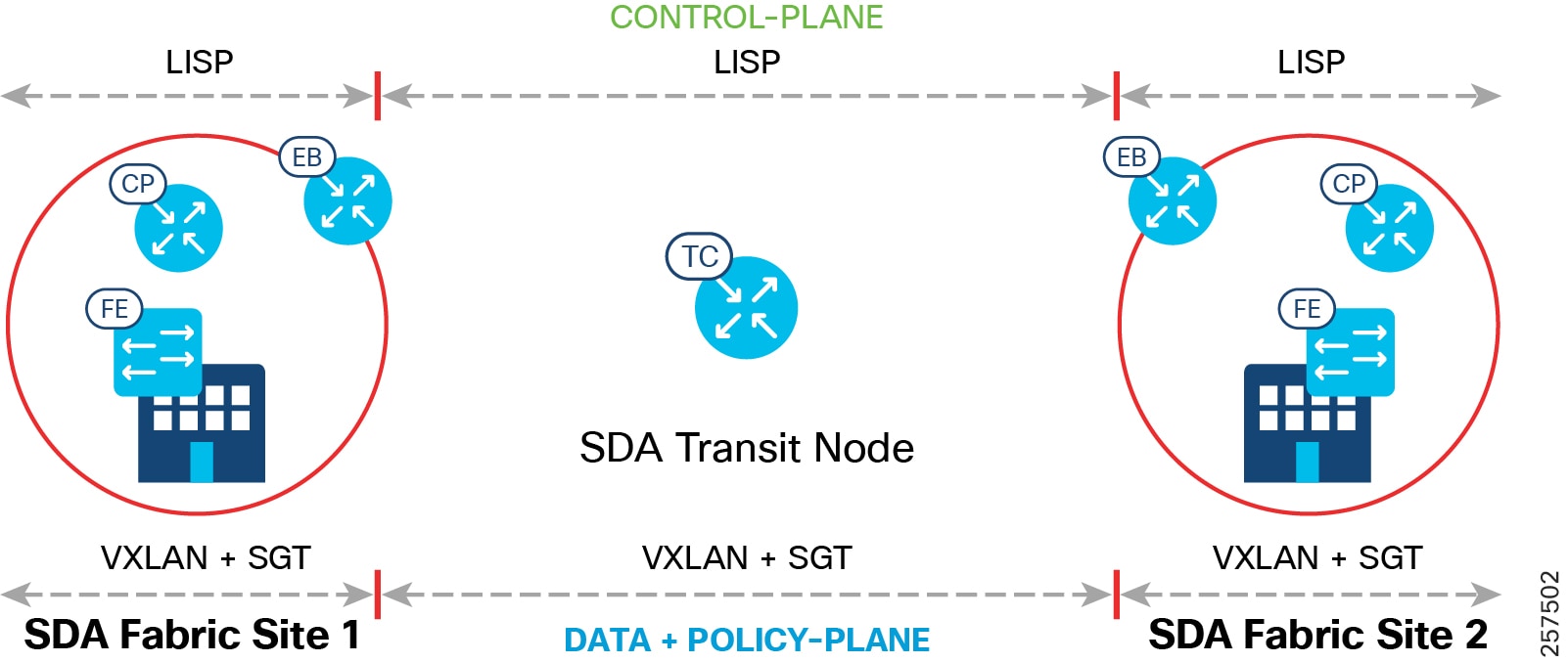
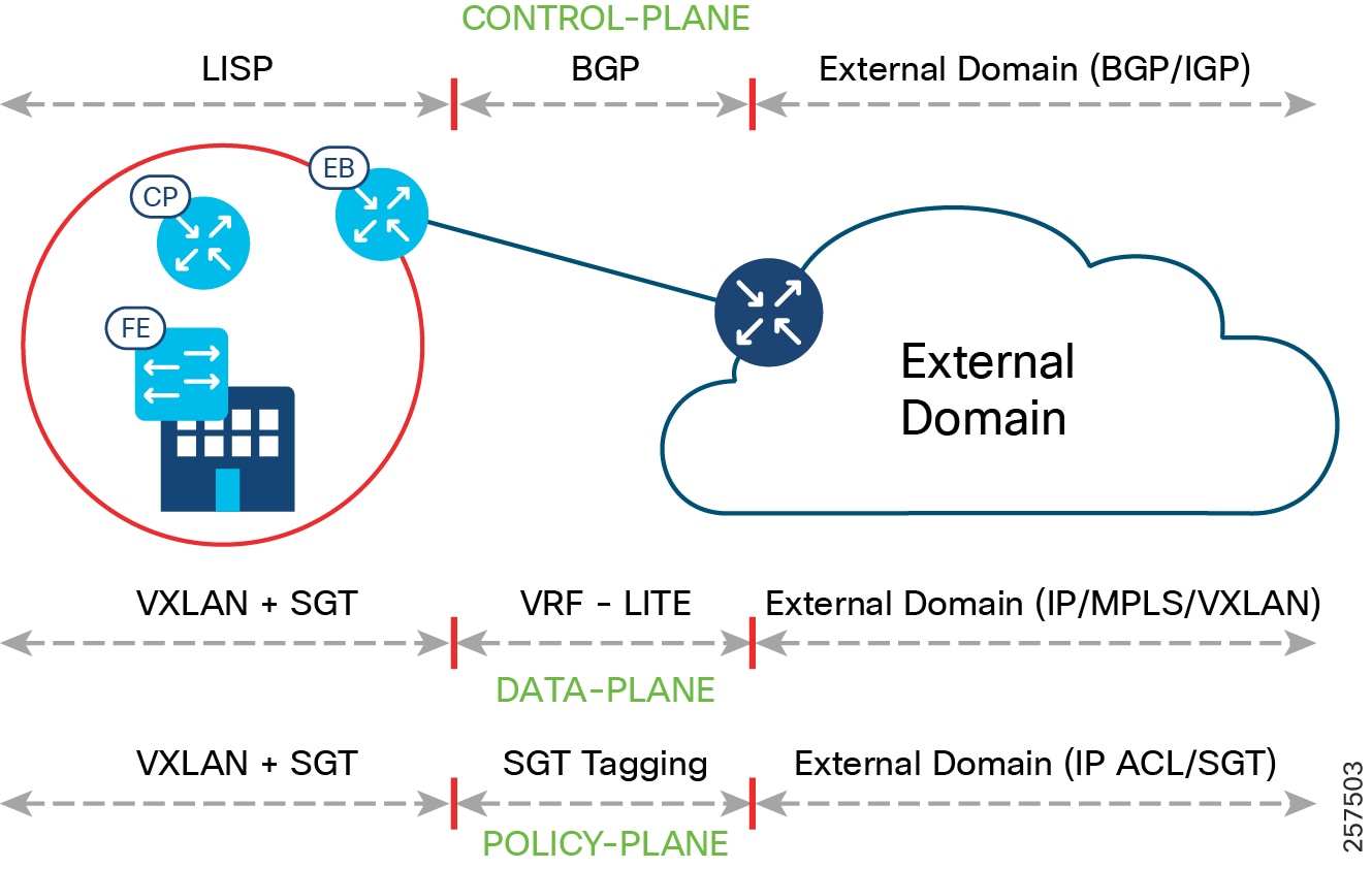
SD-Access transit carries SGT and VN information, with native SD-A encapsulation inherently carrying policy and segmentation between fabric sites; in that way, segmentation is maintained across the fabric sites in a seamless manner. End-to-end configuration of SD-Access transit is automated by the Cisco DNA Center. The control, data, and policy plane mapping across the SD-A Transit is shown in Figure 4. All inter fabric-site traffic passes through SD-A Transit.
Figure 4 SD-Access Transit Data, Control, and Policy Plane Mapping
SGT Tag Mapping in an IP-based Transit Network
The list of VNs that need to communicate with the external world are selected at the border IP-based transit interface. The control, data, and policy plane mapping from the SD-A fabric to the external non-fabric domain is shown in Figure 5. Multiple fabric sites can interconnect via an external network using IP-based transit.
Figure 5 IP-based transit Data, Control, and Policy Plane Mapping
SGT Tag and Policy Derivation in a Network with IP-based Transit and SD-Access Transit
As discussed earlier macro segmentation is maintained by VN mapped to VRF. Micro segmentation within a VN is achieved with the help of scalable groups represented by scalable group tags (SGT). The micro segmentation policy is defined by SGACL. For policy enforcement both the source and destination SGTs are derived and SGACLs are applied. The source fabric edge derives the source SGT from binding information and configures it in the VXLAN header. However, the VXLAN header information is lost while the packet traverses the IP-based transit network as in-line tagging is not supported, so for policy enforcement the SGT binding for the source and destination need to be derived at the destination. In case of IP-based transit, manual SXP tunnel configuration per VN needs to be done on the fabric border and ISE to retrieve SGT binding information from ISE. The destination fabric derives both source SGT and destination SGT from the binding information. For better scalability, it is preferable to configure SXP at the FB instead of FE.
In the case of SD-Access transit, the VXLAN header (VN + SGT info) is retained across the transit network thus no SXP configuration needs to be done for this. The SGTs are propagated from the source fabric to the destination fabric through in-line tagging within the VXLAN header.
Enterprise QoS Overview
QoS refers to the ability of a network to provide preferential or differential services to selected network traffic. QoS can ensure efficient usage of network resources while still adhering to the business objectives. An end-to-end QoS policy of a network can be configured using application policies provided by the Cisco DNA Center.
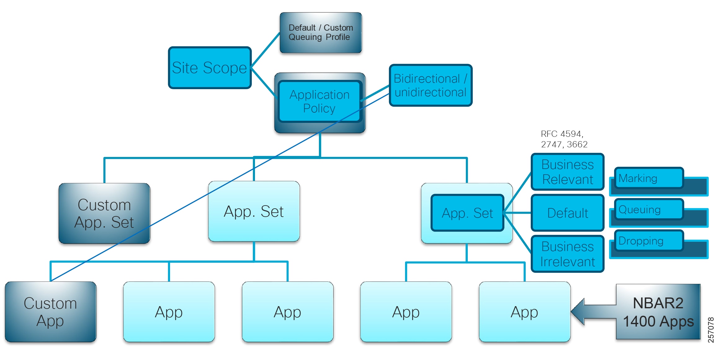
The Cisco DNA Center Application Policy constructs and their organization is depicted in Figure 6.
■![]() Applications and Application Sets—Applications are the software programs or network signaling protocols. The Cisco DNA Center comes with a set of distinct applications listed in Cisco Next Generation Network-Based Application Recognition (NBAR2) library. Each application is mapped into similar industry standards-based traffic classes, as defined in RFC 4594. The traffic classification defines a DSCP marking, queuing, and dropping policy to be applied based on the business relevance group to which it is assigned.
Applications and Application Sets—Applications are the software programs or network signaling protocols. The Cisco DNA Center comes with a set of distinct applications listed in Cisco Next Generation Network-Based Application Recognition (NBAR2) library. Each application is mapped into similar industry standards-based traffic classes, as defined in RFC 4594. The traffic classification defines a DSCP marking, queuing, and dropping policy to be applied based on the business relevance group to which it is assigned.
■![]() Custom applications can be defined for wired devices that are not included in NBAR2. Custom applications can be defined based on server name, IP address and port, or URL. DSCP and port can also be specified for custom applications.
Custom applications can be defined for wired devices that are not included in NBAR2. Custom applications can be defined based on server name, IP address and port, or URL. DSCP and port can also be specified for custom applications.
■![]() Site Scope—Network hierarchy or sites to which an application policy is applied. If you configure a wired policy, the policy is applied to all the wired devices in the site scope. Likewise, if you configure a wireless policy for a selected service set identifier (SSID), the policy is applied to all of the wireless devices with the SSID defined in the site scope. Wired and wireless devices can have differences in the behavior, in terms of bandwidth and packet loss. Individual wireless segments may exhibit further variations. Customized policies can be created matching the characteristics of the segment and applied.
Site Scope—Network hierarchy or sites to which an application policy is applied. If you configure a wired policy, the policy is applied to all the wired devices in the site scope. Likewise, if you configure a wireless policy for a selected service set identifier (SSID), the policy is applied to all of the wireless devices with the SSID defined in the site scope. Wired and wireless devices can have differences in the behavior, in terms of bandwidth and packet loss. Individual wireless segments may exhibit further variations. Customized policies can be created matching the characteristics of the segment and applied.
■![]() Queuing Profile—Queuing profiles define interface bandwidth allocation based on the interface speed and the traffic class.
Queuing Profile—Queuing profiles define interface bandwidth allocation based on the interface speed and the traffic class.
■![]() Business Relevance—Three classes of business relevance groups are defined:
Business Relevance—Three classes of business relevance groups are defined:
–![]() Business Relevant—Maps to industry best-practice preferred-treatment recommendations prescribed in IETF RFC 4594.
Business Relevant—Maps to industry best-practice preferred-treatment recommendations prescribed in IETF RFC 4594.
–![]() Default—Maps to a neutral-treatment recommendation prescribed in IETF RFC 2474 as “Default Forwarding.”
Default—Maps to a neutral-treatment recommendation prescribed in IETF RFC 2474 as “Default Forwarding.”
–![]() Business Irrelevant—Maps to a deferred-treatment recommendation prescribed in IETF RFC 3662.
Business Irrelevant—Maps to a deferred-treatment recommendation prescribed in IETF RFC 3662.
■![]() Unidirectional and Bidirectional Application Traffic—By default, the Cisco DNA Center configures all applications on switches and wireless controllers as unidirectional, and on routers as bidirectional. However, any application within a particular policy can be updated as unidirectional or bidirectional.
Unidirectional and Bidirectional Application Traffic—By default, the Cisco DNA Center configures all applications on switches and wireless controllers as unidirectional, and on routers as bidirectional. However, any application within a particular policy can be updated as unidirectional or bidirectional.
■![]() Consumers and Producers—A traffic relationship between applications (a-to-b traffic flow) can be defined that needs to be handled in a specific way. The applications in this relationship are called producers and consumers. Setting up this relationship allows you to configure specific service levels for traffic matching this scenario.
Consumers and Producers—A traffic relationship between applications (a-to-b traffic flow) can be defined that needs to be handled in a specific way. The applications in this relationship are called producers and consumers. Setting up this relationship allows you to configure specific service levels for traffic matching this scenario.
The Cisco DNA Center takes all of these parameters and translates them into the proper device CLI commands. When you deploy the policy, the Cisco DNA Center configures these commands on the devices defined in the site scope. The Cisco DNA Center configures QoS policies on devices based on the QoS feature set available on the device.
For more information about QoS implementation, refer to the Cisco DNA Center User Guide at the following URL:
■![]() https://www.cisco.com/c/en/us/support/cloud-systems-management/dna-center/products-user-guide-list.html
https://www.cisco.com/c/en/us/support/cloud-systems-management/dna-center/products-user-guide-list.html
Figure 6 Cisco DNA Center Application Policy Construct
Enterprise Wireless Network
The key components of enterprise wireless network are APs and WLCs. In a Cisco DNA Center-enabled network, intent-driven network management of AP and WLC is provided by the Cisco DNA Center. The WLC simplifies network management by centralizing the configuration and control of WAPs. This design approach allows the Wireless LAN (WLAN) to operate as an intelligent information network and support advanced services.
All APs obtain their operating system and configurations from the WLC, which performs centralized radio resource management with a global view of the network, thus improving the overall performance with better radio coverage and best use of available frequencies.
Refer to the following documents for details on Cisco SD-Access and traditional wireless network design:
■![]() SD-Access Wireless Design and Deployment Guide at the following URL:
SD-Access Wireless Design and Deployment Guide at the following URL:
–![]() https://www.cisco.com/c/en/us/td/docs/wireless/controller/technotes/8-5/b_SD_Access_Wireless_Deployment_Guide.html
https://www.cisco.com/c/en/us/td/docs/wireless/controller/technotes/8-5/b_SD_Access_Wireless_Deployment_Guide.html
■![]() Campus Wired and Wireless LAN CVD at the following URL:
Campus Wired and Wireless LAN CVD at the following URL:
–![]() https://www.cisco.com/c/en/us/solutions/design-zone/networking-design-guides/campus-wired-wireless.html#~stickynav=1
https://www.cisco.com/c/en/us/solutions/design-zone/networking-design-guides/campus-wired-wireless.html#~stickynav=1
Extended Enterprise Network
The Extended Enterprise network, as shown in Figure 7, is an extension from the carpeted enterprise network described in Extended Enterprise Network and Enterprise Wireless Network to its non-carpeted outdoor corridors. This layer is coined the “Extended Access Layer.” Both wired and wireless network services are provided in the Extended Enterprise. The Extended Enterprise network uses ruggedized IE access switches such as the Cisco IE2000 series, Cisco IE3x00 series, Cisco IE4000 series, and Cisco IE5000 series, and outdoor APs such as the Cisco Aironet 1560, Cisco Aironet 1542, Cisco IW3702, and Cisco IW6300. Different endpoints such as security cameras, wireless clients, and display terminals connect to the Extended Access Layer.
This section describes the design details of the extended network, including roles, topology, solution components, wireless integration, and policy applications.
Figure 7 Enterprise Network Design with Both SD-Access Fabric and Non-Fabric Deployment
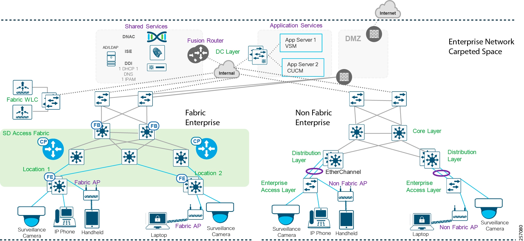
The enterprise can be SD-Access fabric enabled or non-fabric. Some deployments can have a combination (as shown in Figure 7). This CVD discusses both designs. Specifics for each deployment will be called out in the different sections.
Each building floor/geographic location has enterprise access switches, preferably on a stack configuration. Ruggedized IE switches are configured as Extended Enterprise access nodes, which connect to the enterprise access switch and thus extend the enterprise network to non-carpeted space. Both wireless and wired connectivity are provided in the Extended Enterprise region. In case of fabric deployment each fabric site has a dedicated WLC and in case of non-fabric deployment a single WLC is centrally located, managing APs both in the enterprise and the Extended Enterprise space. For network latency requirements for WLC connectivity, refer to the Cisco DNA Center User Guide.
Security and QoS policies are applied uniformly, providing uniform treatment for a given service across the Enterprise and Extended Enterprise network. Controlled access is given to shared services and other internal networks by appropriate authorization profile assignment.
Redundancy is provided for devices and links at various levels. Details are covered in High Availability, Reliability, and Scale of Extended Networks to Meet Operational Needs.
The internet connection is protected with a firewall. Extended network design is based on existing campus networks. For more details, refer to the following links:
Reference for SD-Access deployments: Cisco Digital Network Architecture:
■![]() https://www.cisco.com/c/en/us/solutions/design-zone/networking-design-guides/digital-network-architecture-design-guides.html
https://www.cisco.com/c/en/us/solutions/design-zone/networking-design-guides/digital-network-architecture-design-guides.html
Reference for non-fabric deployments: Campus Wired and Wireless LAN website:
■![]() https://www.cisco.com/c/en/us/solutions/design-zone/networking-design-guides/campus-wired-wireless.html
https://www.cisco.com/c/en/us/solutions/design-zone/networking-design-guides/campus-wired-wireless.html
Extended Enterprise Design Considerations
The Extended Enterprise design is flexible enough to suit any campus outdoor requirement. There is no “one size fits all.” This document serves as a reference design for typical small, medium, and large density requirements. Extended Enterprise, as the name suggests, is an extension to an existing enterprise network.
The following design and constructs are leveraged by the Extended Enterprise from the enterprise network:
–![]() Either SD-Access deployment or Cisco DNA Center-managed non-fabric enterprise: Cisco DNA Center, core, distribution and access, and all shared services or Cisco SD-Access deployment.
Either SD-Access deployment or Cisco DNA Center-managed non-fabric enterprise: Cisco DNA Center, core, distribution and access, and all shared services or Cisco SD-Access deployment.
–![]() Available end-to-end network redundancy.
Available end-to-end network redundancy.
■![]() Design for network scaling for access and the Cisco DNA Center
Design for network scaling for access and the Cisco DNA Center
The following design considerations for the Extended Enterprise network are listed in this section:
■![]() Different categories of design considerations include design, provisioning, policy and assurance of Extended Enterprise networks, devices, hosts, and services.
Different categories of design considerations include design, provisioning, policy and assurance of Extended Enterprise networks, devices, hosts, and services.
■![]() Frequently, enterprise networks spread across multiple buildings and multiple geographies. The Extended Enterprise will have similar characteristics covering the non-carpeted space in each of the locations. Multiple enterprise fabric locations are interconnected by either private controllable WAN connectivity or public uncontrollable WAN connectivity.
Frequently, enterprise networks spread across multiple buildings and multiple geographies. The Extended Enterprise will have similar characteristics covering the non-carpeted space in each of the locations. Multiple enterprise fabric locations are interconnected by either private controllable WAN connectivity or public uncontrollable WAN connectivity.
■![]() The Extended Enterprise is an extension to the enterprise services; therefore, the traffic characteristics (for example, QoS and segmentation) uniformly apply. The QoS policy of the enterprise network should be applied to all Enterprise Access Layer devices. The traffic from the Enterprise and Extended Enterprise need to co-exist and share the resources.
The Extended Enterprise is an extension to the enterprise services; therefore, the traffic characteristics (for example, QoS and segmentation) uniformly apply. The QoS policy of the enterprise network should be applied to all Enterprise Access Layer devices. The traffic from the Enterprise and Extended Enterprise need to co-exist and share the resources.
■![]() The Extended Enterprise design revolves around extending the enterprise network to the non-carpeted area using Cisco ruggedized switches (IE switches) and APs.
The Extended Enterprise design revolves around extending the enterprise network to the non-carpeted area using Cisco ruggedized switches (IE switches) and APs.
■![]() All Cisco DNA Center-supported models of access switches and APs suitable for Extended Enterprise use cases can be considered.
All Cisco DNA Center-supported models of access switches and APs suitable for Extended Enterprise use cases can be considered.
■![]() Extended Enterprise scale consideration: The size of the parent enterprise can range from small to large, so too can the scale of the Extended Enterprise.
Extended Enterprise scale consideration: The size of the parent enterprise can range from small to large, so too can the scale of the Extended Enterprise.
■![]() Extended Enterprise will have several categories of services or service groups. Different categories of services need to be isolated from each other, and only controlled communication should be possible between services of different service categories.
Extended Enterprise will have several categories of services or service groups. Different categories of services need to be isolated from each other, and only controlled communication should be possible between services of different service categories.
■![]() The application servers catering to specific services need to have exclusive access only to authorized devices and clients.
The application servers catering to specific services need to have exclusive access only to authorized devices and clients.
■![]() High availability design for end-to-end redundancy.
High availability design for end-to-end redundancy.
In summary, the key design components of Extended Enterprise are:
■![]() Ruggedized switches, outdoor APs, shared services, and hosts connected to the extended access layer.
Ruggedized switches, outdoor APs, shared services, and hosts connected to the extended access layer.
■![]() Devices, hosts authentication, and isolation of different categories of traffic.
Devices, hosts authentication, and isolation of different categories of traffic.
■![]() The enterprise network can span multiple buildings and geographies.
The enterprise network can span multiple buildings and geographies.
Two different deployment scenarios are:
■![]() Scenario A—Enterprises having deployed Cisco DNA Center, but not deployed Cisco SD-Access fabric, as shown in Figure 5. This scenario is referred in this document as Extended Enterprise non-fabric deployment.
Scenario A—Enterprises having deployed Cisco DNA Center, but not deployed Cisco SD-Access fabric, as shown in Figure 5. This scenario is referred in this document as Extended Enterprise non-fabric deployment.
■![]() Scenario B—Enterprises having deployed Cisco DNA Center and Cisco SD-Access. This scenario is referred in this document as Extended Enterprise SD-Access deployment.
Scenario B—Enterprises having deployed Cisco DNA Center and Cisco SD-Access. This scenario is referred in this document as Extended Enterprise SD-Access deployment.
Extended Enterprise Solution Components for Non-Fabric Deployments
Cisco has a range of IE switches and APs suitable for outdoor deployment as shown in Table 1. A reference list of components for the enterprise network is shown in Table 2.
As shown in Table 1, IE switches can play the role of access on non-fabric deployments.
Extended Enterprise Solution Components for Cisco SD-Access Deployments
Cisco has a range of IE switches and APs suitable for SD-Access fabric outdoor deployment as shown in Table 3 and in Table 5. A reference list of components for the enterprise network is shown in Table 4.
Tech Tip: Extended node functionality is not supported on Cisco IE2000 and Cisco IE3200 switches.
Tech Tip: Devices that support extended nodes/policy extended nodes are the Cisco Catalyst 9300, Cisco Catalyst 9400, and Cisco Catalyst 9500 series switches when configured as fabric edge. Cisco Catalyst 9200 series switches do not support extended nodes.
Extended Enterprise Solution Wireless Components
Table 5 has APs recommended for Extended Enterprise deployment and IP video surveillance camera used for validation.
Extended Enterprise Non-Fabric Design
The Cisco DNA Center-managed, Non-fabric enterprise follows a standard architecture similar to the one published in the Cisco Enterprise Network CVD and Campus Wired and Wireless LAN CVD. The design enables wired and wireless communications between devices in an outdoor or a group of outdoor environments, as well as interconnection to the WAN and Internet edge at the network core.
■![]() Network is extended to non-carpeted spaces by connecting industrial switches to the distribution layer as explained in the figure in Extended Enterprise Wired Access.
Network is extended to non-carpeted spaces by connecting industrial switches to the distribution layer as explained in the figure in Extended Enterprise Wired Access.
■![]() A redundancy protocol should be used in distribution layer for high availability. StackWise was used for CVD validation.
A redundancy protocol should be used in distribution layer for high availability. StackWise was used for CVD validation.
■![]() Existing enterprise wireless can be used for non-carpeted spaces. Wireless options are covered in Extended Enterprise Wireless Access.
Existing enterprise wireless can be used for non-carpeted spaces. Wireless options are covered in Extended Enterprise Wireless Access.
■![]() Enterprise security policies can be used on carpeted and non-carpeted spaces as explained in Extended Enterprise Security Policy Design.
Enterprise security policies can be used on carpeted and non-carpeted spaces as explained in Extended Enterprise Security Policy Design.
■![]() Application policy design is covered in Extended Enterprise QoS Policy Design.
Application policy design is covered in Extended Enterprise QoS Policy Design.
Figure 8 Extended Enterprise Non-Fabric Design

Extended Enterprise SD-Access Fabric Design
The Cisco SD-Access deployment is based on the Software-Defined Access Design Guide. SD-Access is the Cisco DNA evolution from traditional campus LAN designs to networks that directly implement the intent of an organization. SD-Access is enabled with an application package that runs as part of the Cisco DNA Center software. It simplifies network management by providing design and provision tools; provides intent by allowing simplified policy provision; and adds intelligence with assurance tools for proactive monitoring and troubleshooting. The Extended Enterprise SD-Access design uses a fabric site deployment that could span to multiple locations. Multiple fabric sites can be interconnected by either IP-based transit or SD-Access transit network.
■![]() Network is extended to non-carpeted spaces by connecting extended nodes to fabric edge nodes using port-channel.
Network is extended to non-carpeted spaces by connecting extended nodes to fabric edge nodes using port-channel.
■![]() A redundancy protocol should be used in the distribution layer for high availability. StackWise was used for CVD validation.
A redundancy protocol should be used in the distribution layer for high availability. StackWise was used for CVD validation.
■![]() Wireless deployment from the enterprise can be used for non-carpeted spaces. Centralized or SD-Access wireless can be used as explained in Extended Enterprise Wireless Deployment Model.
Wireless deployment from the enterprise can be used for non-carpeted spaces. Centralized or SD-Access wireless can be used as explained in Extended Enterprise Wireless Deployment Model.
■![]() Enterprise security policies can be used on carpeted and non-carpeted spaces as explained in Extended Enterprise Security Policy Design.
Enterprise security policies can be used on carpeted and non-carpeted spaces as explained in Extended Enterprise Security Policy Design.
■![]() Application policy design is covered in Extended Enterprise QoS Policy Design.
Application policy design is covered in Extended Enterprise QoS Policy Design.
The Extended Enterprise SD-Access design leverages extended nodes and policy extended nodes to extend connectivity and macro and micro segmentation policy to harsh outdoor environments and non-carpeted spaces. Network advantage license is needed to configure a device as EN or PEN.
SD-Access Policy Extended Nodes
Starting from Cisco SD-Access 1.3.3 release, devices such as IE3400 and IE3400H series having minimum software version 17.1.1s and directly connected to FE/FiaB can be configured as PEN. PEN extends SD-Access fabric.
Note: Refer to Table 3 for CVD validated and recommended software versions.
Endpoints connected to PEN can be authenticated by ISE with 802.1x or MAB. On successful endpoint authentication, authorization policy is applied by ISE and appropriate VLAN and SGT are pushed on to the PEN source access port, shown in Figure 9. This allows micro segmentation to be extended down to the PEN.
PEN enforces SGACL policy for all east-west traffic destined within the source PEN. For all traffic destined outside source PEN, source SGT is tagged and propagated to connected FE with inline tagging. In the rest of the native SD-A network, SGTs are carried in VXLAN headers and enforcement is done at the fabric exit.
Note: IE3400 and IE3400H devices having OS version 17.1.1s or above, having no initial configuration, when connected to FE are default auto-provisioned as PEN on bootup. IE3400 and IE3400H devices having lower OS version or having some configuration on initial bootup are auto-provisioned as EN.
Figure 9 Authorization Policy Assignment for Extended Node and Policy Extended Node Endpoints
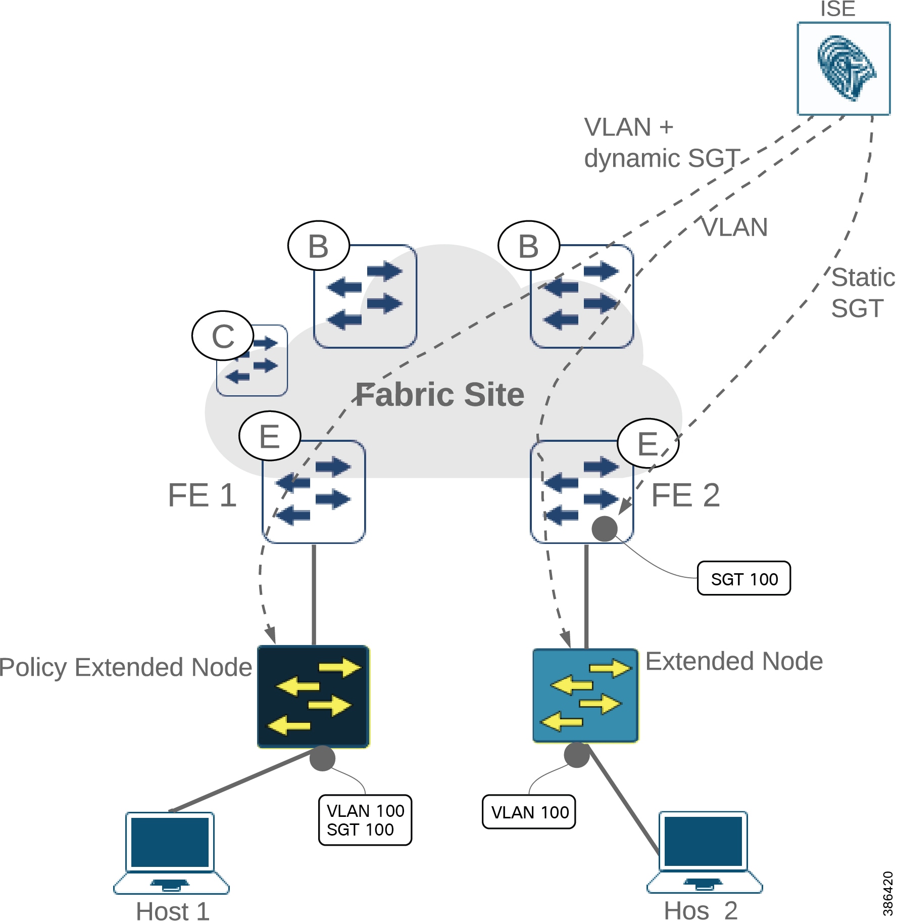
SD-Access Extended Node
SD-Access supp ort for extended nodes is a fabric feature that extends consistent, policy-based automation to Cat IE3300, IE3400, IE4000, and IE5000 series switches connected directly to an FE. An EN operates in Layer 2 switch mode. EN connects to fabric edge nodes using 802.1Q trunk EtherChannel and are onboarded with zero-touch Plug-and-Play.
Endpoint authentication with 802.1x or MAB is supported by EN. On successful endpoint authentication, authorization policy is applied by ISE and appropriate VLAN is pushed on to the source access port. For micro segmentation, static IP-SGT can be configured by DNAC and pushed to the FE to which the EN is connected.
East-west traffic destined within the source EN is not subjected to SGT based policy enforcement. East-west traffic destined outside the source EN is forwarded to FE, where VLANs are mapped to source SGT. The source SGT is carried to destination. The destination FE enforce SGACL policy based on source and destination SGT.
Note: To avoid unexpected random behavior, care should be taken to ensure that static SGT mapping for endpoints connected to EN and dynamic SGT mapping for endpoints connected to PEN are identical.
Extended Enterprise Single Fabric Network
Figure 10 shows design of an single fabric Extended Enterprise network. The single fabric network can have multiple fabric edges. As shown in Figure 10 the single fabric network is connected to the external world with a fusion router.
Figure 10 Extended Enterprise SD-Access Network Design with Single Fabric
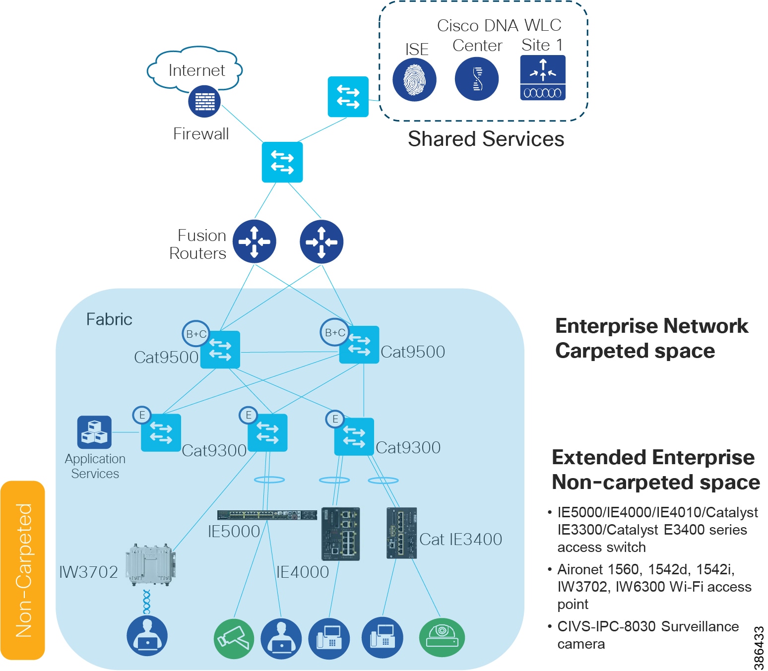
Extended Enterprise Multi-site Fabric Network with SD-Access Transit
Figure 11 shows Extended Enterprise Network design with SD-Access transit. The network sites that have a campus like (high speed, low latency, and Jumbo MTU support) connectivity with Cisco DNA Center are interconnected with SD-Access transit. A core device called fusion router interconnects shared services, Internet to all fabric sites in the network.
Figure 11 Extended Enterprise Multi-site Fabric Network with SD-Access Transit
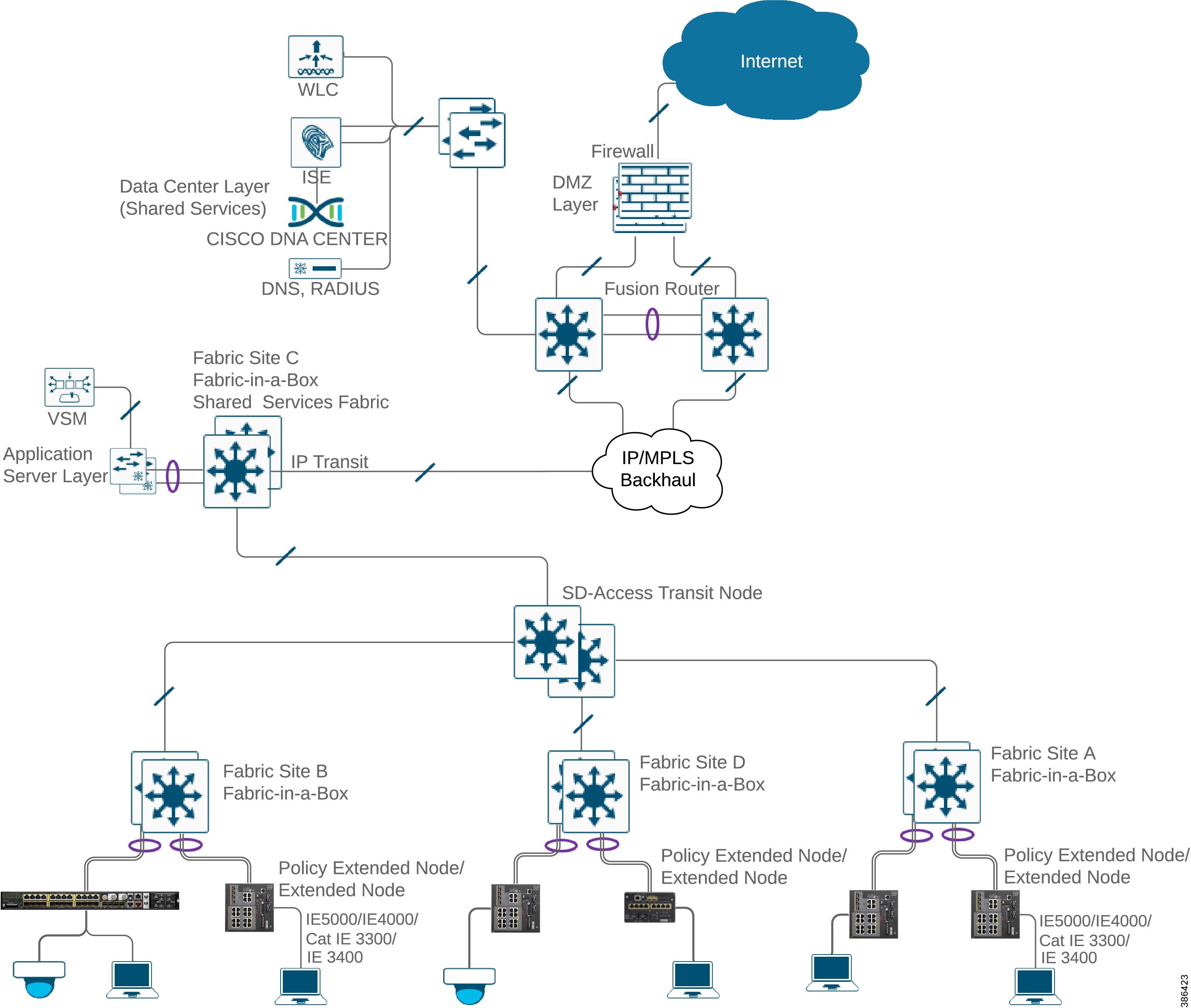
Extended Enterprise Multi-site Fabric Network with IP-based Transit
Figure 12 shows Extended Enterprise Network design with IP-based transit. The network sites that have a WAN kind of IP/MPLS backbone are interconnected with IP-based transit. A core device called fusion router interconnects shared services, Internet to all fabric sites in the network.
Figure 12 Extended Enterprise Multi-site Fabric Network with IP Transit
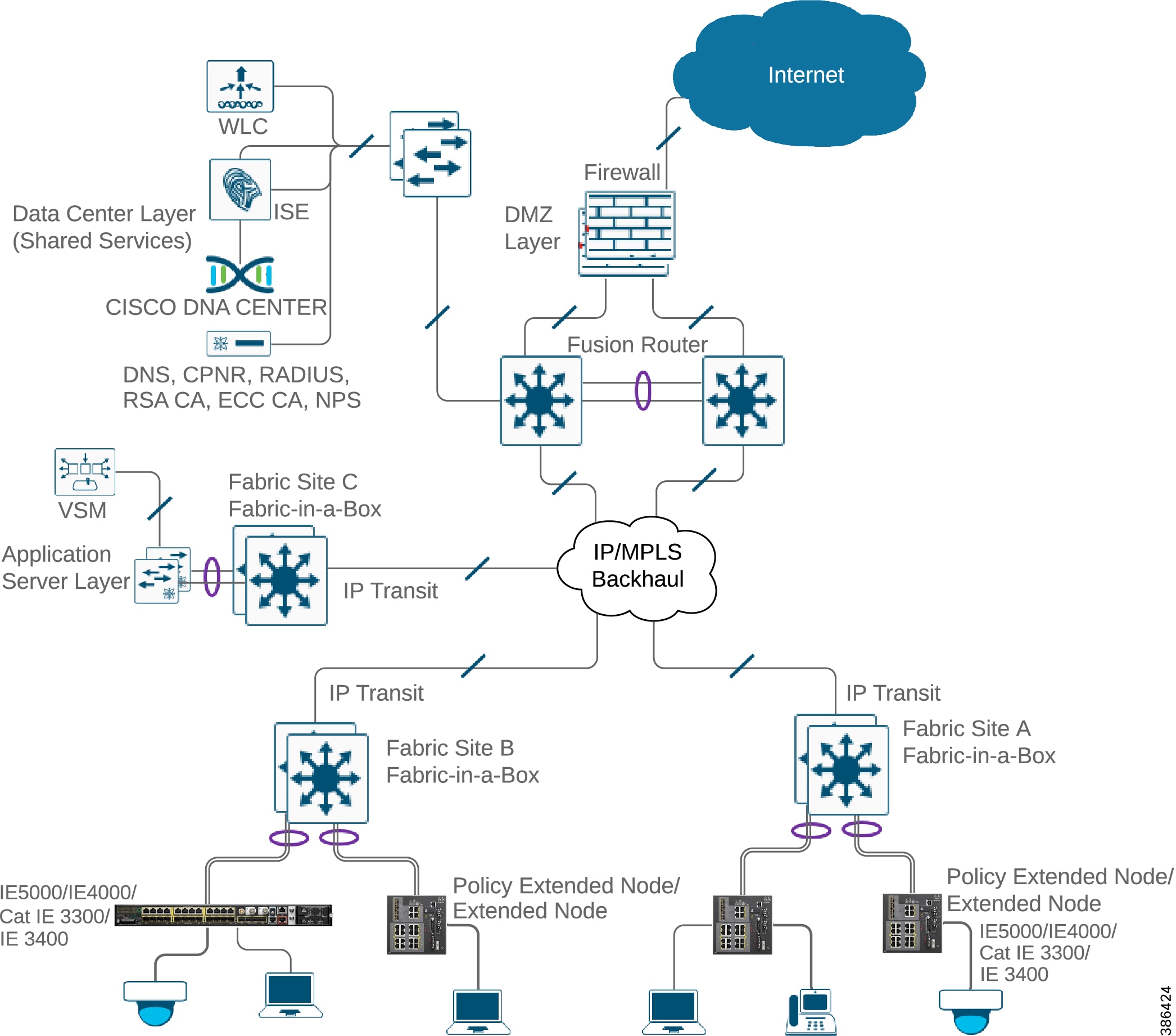
Extended Enterprise Multi-site Fabric Network Having Both SD-Access and IP-based Transit
Figure 13 shows Extended Enterprise Network design having both SD-Access and IP-based transit. The network sites that have a campus like (high speed, low latency, and Jumbo MTU support) connectivity with Cisco DNA Center are interconnected with SD-Access transit. The network sites that have a WAN kind of IP/MPLS backbone are interconnected with IP-based transit. A core device called fusion router interconnects shared services, Internet to all fabric sites in the network, irrespective of their backbone.
Figure 13 Extended Enterprise Multi-site Fabric Network Having Both SD-Access and IP-based Transit
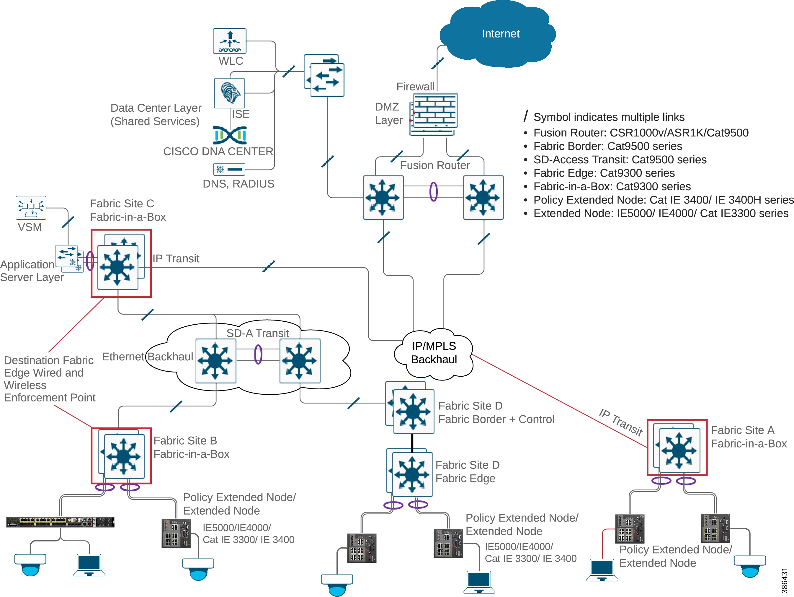
Extended Enterprise Wired Access
Extended Enterprise wired access is provided with ruggedized IE switches. The IE switches are connected directly in a star topology to the enterprise network edge switches. Based on the availability of ports on the access switch and IE switch models, both fiber and copper up-links can be used.
Star Topology
Access switches connecting in a star topology are shown in Figure 14. Multiple up-links of an IE switch can connect to multiple distribution layer switches arranged in a stack using EtherChannel. The distribution layer switches can be deployed in a StackWise configuration for redundancy. The EtherChannel at the stack is seen as a single link providing load balancing and loop avoidance.
Figure 14 Extended Enterprise Access Network Topology
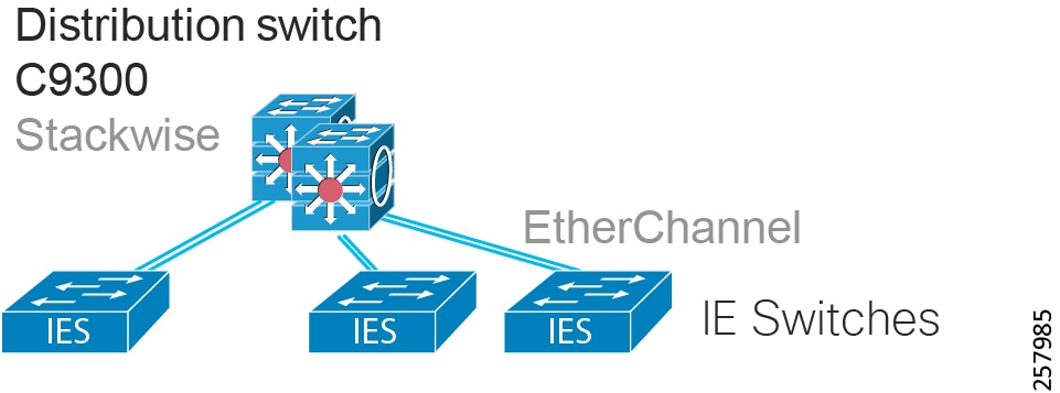
Tip: In fabric deployments, extended nodes must be connected to the fabric using EtherChannel.
Choice of Access Switches
The enterprise wired access network is extended in uncontrolled environments using ruggedized Cisco industrial switches as explained in SD-Access Extended Node. Refer to Table 6 for specific model support.
Minimum SW version required for SD-Access extended node/policy extended node |
|||||
|---|---|---|---|---|---|
Tip: On SD-Access deployments, the Cisco Catalyst 9300, Cisco Catalyst 9400, and Cisco Catalyst 9500 series switches are the edge devices that can be used to connect extended nodes when configured as fabric edge.
By choosing appropriate switch models, both copper and fiber access can be provided. All IE switches are managed by the Cisco DNA Center and just like with any Catalyst switch, all Cisco DNA Center features such as discovery, inventory, topology, Software Image Management (SWIM), and assurance apply to these switches and hosts connected to these switches.
For more feature information, refer to the Cisco DNA Center end user guides at the following URL:
■![]() https://www.cisco.com/c/en/us/support/cloud-systems-management/dna-center/products-user-guide-list.html
https://www.cisco.com/c/en/us/support/cloud-systems-management/dna-center/products-user-guide-list.html
Wired hosts such as camera and laptop in the Extended Enterprise region can be connected to the enterprise access, if reachable to Extended Enterprise IE switches.
Various access layer features such as multiple access ports, copper or fiber access ports, PoE/PoE+, multi-GB access and uplink are supported:
■![]() Port security and TrustSec options are supported on non-fabric deployments; for details on access ports security, see Securing the Wired and Wireless Network Access.
Port security and TrustSec options are supported on non-fabric deployments; for details on access ports security, see Securing the Wired and Wireless Network Access.
■![]() For SD-Access deployments, security options are explained in Security Design Considerations for SD-Access Deployments.
For SD-Access deployments, security options are explained in Security Design Considerations for SD-Access Deployments.
Extended Enterprise Wireless Access
Extended Wi-Fi wireless access is provided in the Extended Enterprise region using outdoor access points having Cisco DNA Center support such as the AP1560 series, AP1542 series, IW3702, and IW6300. They can be connected to any access IE switch in the extended access, to provide wireless connectivity in the outdoor non-carpeted area. The APs form a Control and Provisioning of Wireless Access Points (CAPWAP) tunnel with the WLC. On non-fabric deployments all wireless data, control and management flow through the CAPWAP.
In SD-Access wireless, the control plane is centralized; this means that, as with Cisco Unified Wireless Network (CUWN), a CAPWAP tunnel is maintained between APs and the WLC. The main difference is that the data plane is distributed using VXLAN directly from the fabric-enabled APs. WLC and APs are integrated into the fabric and the APs connect to the fabric overlay (EID space) network as “special” clients.
Extended Enterprise Wireless Access Design Considerations
The main objective of the Extended Enterprise wireless design is to provide the same experience for users connected to the outdoor APs as for the traditional campus users. Various considerations to be taken into account while designing the Extended Enterprise wireless network include:
■![]() Extended Enterprise wireless access spans across multiple building and geographies.
Extended Enterprise wireless access spans across multiple building and geographies.
■![]() To cater to Extended Enterprise use cases, APs need to have the following capability:
To cater to Extended Enterprise use cases, APs need to have the following capability:
–![]() Ruggedized enclosure, 802.11ac Wi-Fi support, support for both 2.4Ghz and 5Ghz Wi-Fi radio
Ruggedized enclosure, 802.11ac Wi-Fi support, support for both 2.4Ghz and 5Ghz Wi-Fi radio
■![]() Uniform wireless across carpeted and non-carpeted space:
Uniform wireless across carpeted and non-carpeted space:
–![]() Same SSID across carpeted and non-carpeted space
Same SSID across carpeted and non-carpeted space
–![]() Same user credentials across carpeted and non-carpeted space
Same user credentials across carpeted and non-carpeted space
–![]() Provision for exclusive SSIDs in non-carpeted space if desired
Provision for exclusive SSIDs in non-carpeted space if desired
–![]() Configurable authorization policy
Configurable authorization policy
–![]() Seamless mobility between carpeted and non-carpeted space
Seamless mobility between carpeted and non-carpeted space
–![]() Support for both voice and data services
Support for both voice and data services
–![]() Support for PoE power for APs
Support for PoE power for APs
–![]() Fast lane (priority treatment for iOS endpoints) and fast-transition (feature for fast roaming) to be supported
Fast lane (priority treatment for iOS endpoints) and fast-transition (feature for fast roaming) to be supported
Extended Enterprise Wireless Deployment Model
To meet the needs explained in previous sections, any of the following wireless deployments models can be implemented. This section covers details for each model. Three types of deployment models and their recommended use are discussed in this section:
■![]() Centralized wireless design, which applies to both non-fabric and SD-Access deployments
Centralized wireless design, which applies to both non-fabric and SD-Access deployments
■![]() FlexConnect wireless design, which applies only to non-fabric deployments
FlexConnect wireless design, which applies only to non-fabric deployments
■![]() SD-Access wireless design, which applies only to SD-Access deployments
SD-Access wireless design, which applies only to SD-Access deployments
In a centralized deployment model, the WLAN is centrally located. All APs connect to the WLAN over a high-speed low-latency link. APs form a CAPWAP tunnel with the WLAN. All wireless traffic (data, control, and management) from the APs is tunneled to the WLC. The WLC is the single point of management for managing Layer 2 security and wireless network policies.
In a centralized deployment model, with the help of Cisco DNA Center and ISE, the policies can be applied in a consistent and coordinated manner across wired and wireless networks. It also greatly simplifies management by automation.
In addition to the traditional benefits of a Cisco Unified Wireless Network, the local-mode design provides the following features:
■![]() Centralized IP address management, simplified configuration, and troubleshooting.
Centralized IP address management, simplified configuration, and troubleshooting.
■![]() Seamless mobility, fast roaming, and roaming at scale support: users remain connected to their session even while walking between various Enterprise and Extended Enterprise zones with changing subnets.
Seamless mobility, fast roaming, and roaming at scale support: users remain connected to their session even while walking between various Enterprise and Extended Enterprise zones with changing subnets.
■![]() Can support rich media such as voice with call admission control.
Can support rich media such as voice with call admission control.
■![]() Centralized policy enables application inspection, network access control, policy enforcement, and accurate traffic classification.
Centralized policy enables application inspection, network access control, policy enforcement, and accurate traffic classification.
This centralized deployment model implementation for Extended Enterprise is detailed in the Extended Enterprise Implementation Guide for Non-Fabric Deployment with Cisco DNA Center at the following URL:
■![]() https://www.cisco.com/go/extendedenterprise
https://www.cisco.com/go/extendedenterprise
The centralized wireless deployment model can be used in SD-Access deployments; in this mode, the SD-Access fabric is simply a transport network for the wireless traffic. This is called Over the Top (OTT); in this scenario, the SD-Access features are not available.
Cisco FlexConnect Local Switching Deployment Model
FlexConnect can be used in non-fabric deployments, where several small, remote locations having WAN connectivity to the central location with high-latency exist. Typically, this applies to enterprises having a central site and several small, remote branch sites.
Key features for FlexConnect local switching deployment model are:
■![]() A cost-effective solution, helping enable enterprises to configure and control remote-site APs from the headquarters through the WAN, without deploying a controller in each remote site.
A cost-effective solution, helping enable enterprises to configure and control remote-site APs from the headquarters through the WAN, without deploying a controller in each remote site.
■![]() APs can switch client data through a local wired network.
APs can switch client data through a local wired network.
■![]() Only guest wireless, control traffic, and Internet traffic are tunneled to centralized WLC over CAPWAP.
Only guest wireless, control traffic, and Internet traffic are tunneled to centralized WLC over CAPWAP.
Either a dedicated FlexConnect WLC or a shared WLC controller can be used to manage FlexConnect mode APs in the network. A list of recommended WLC models and comparison is given in Choice of Wireless LAN Controller.
SD-Access Wireless is defined as the integration of wireless access in the SD-Access architecture in order to gain all the advantages of fabric and Cisco DNA Center automation. Supported Cisco WLCs are configured as fabric wireless controllers to communicate with the fabric control plane, registering Layer 2 client MAC addresses, SGTs, and Layer 2 VNI information.
Fabric is enabled per SSID, and supported fabric APs join the fabric-enabled SSIDs. The APs are responsible for communication with wireless endpoints, and the APs assist the VXLAN data plane by encapsulating and de-encapsulating traffic at the connected node.
Fabric wireless controllers manage and control the fabric mode APs using the same model as the traditional centralized model of local-mode controllers, offering the same operational advantages, such as mobility control and radio resource management. In fabric mode, each WLC is dedicated to a single fabric site. The WLC is connected to fabric border through a IP-based transit backhaul. Figure 15 shows a combined fabric and non-fabric wireless deployment. Each fabric site with wireless, connected to either SD-Access transit or IP-based transit, has a dedicated local WLC. Non-fabric sites can have a shared WLC located at the Data Center. Different models of WLC suitable for different deployments are listed in the figure.
A significant difference is that client traffic carried from wireless endpoints on fabric SSIDs avoids CAPWAP encapsulation and forwarding from the APs to the central controller. Instead, communication from wireless clients is VXLAN-encapsulated by fabric-attached APs. This difference enables a distributed data plane with integrated security capabilities. Moreover, traffic forwarding takes the optimum path through the SD-Access fabric to the destination with consistent policy, regardless of wired or wireless endpoint connectivity.
The control plane communication for the APs uses a CAPWAP tunnel to the WLC, similar to the traditional Cisco Unified Wireless Network control plane. However, the WLC integration with the SD-Access control plane supports wireless clients roaming to APs across the fabric. Integrating the wireless LAN into the fabric enables the fabric advantages for the wireless clients, including addressing simplification, mobility with stretched subnets, and end-to-end segmentation with policy consistency across the wired and wireless domains.
Figure 15 Extended Enterprise SD-Access Fabric and Non-fabric Combined Wireless Deployment
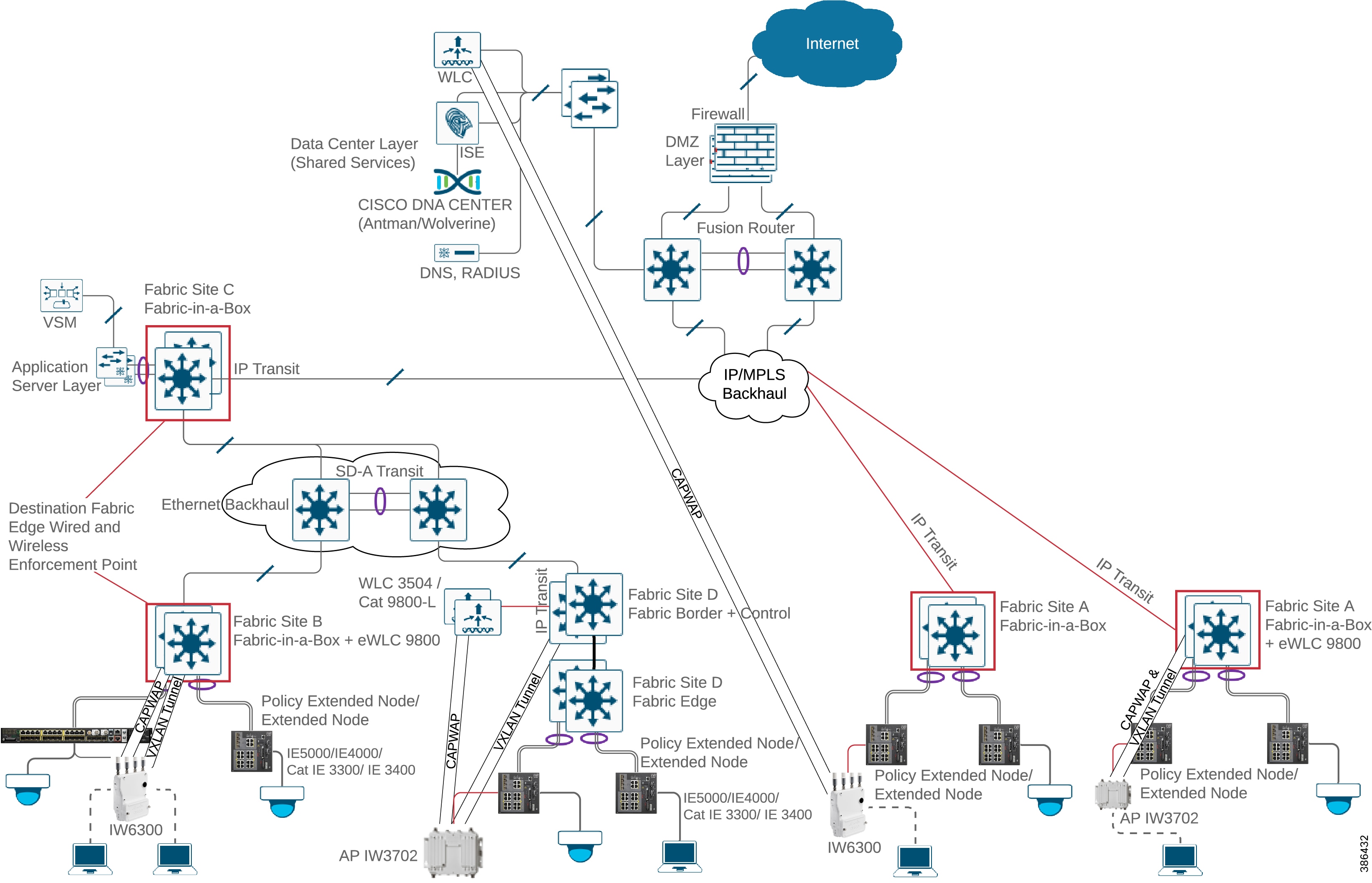
Wireless Deployment Model Summary
Table 7 summarizes what was discussed above comparing the three wireless deployment models.
Guest Wireless
Guest wireless traffic needs to be treated distinctly in the enterprise network but using the existing campus wired and wireless infrastructure for guest access provides a convenient, cost-effective way to offer Internet access for visitors and contractors. The three deployment models discussed above have the option of creating a guest wireless network using existing infrastructure. The wireless guest network provides the following functionality:
■![]() Provide guest Internet access through an Open Wireless SSID, with web authentication access control.
Provide guest Internet access through an Open Wireless SSID, with web authentication access control.
■![]() Define guest access policy having access only to Internet.
Define guest access policy having access only to Internet.
■![]() Guest access policy should not have access to any internal network.
Guest access policy should not have access to any internal network.
■![]() Guest access can be provided in any of the described deployment models.
Guest access can be provided in any of the described deployment models.
For more details on guest networks, refer to the CVD Campus LAN WLAN Design Guide at the following URL:
■![]() https://www.cisco.com/c/en/us/solutions/design-zone/networking-design-guides/campus-wired-wireless.html
https://www.cisco.com/c/en/us/solutions/design-zone/networking-design-guides/campus-wired-wireless.html
Security for Wireless Clients
SSIDs can either be shared or exclusive between the Enterprise and Extended Enterprise network. In the case of shared SSID, seamless roaming will be supported between the Extended Enterprise and the Enterprise network.
Wireless clients/users are mapped to user groups at ISE and authorization is defined for each user group. This holds true both for wireless and wired groups keeping their credentials and access rights the same. Wireless users obtain the same access rights as they roam around the Extended Enterprise and Enterprise networks. Considerations for security policy enforcement for SD-Access and non-fabric deployments are described in Extended Enterprise Security Policy Design.
Choice of Access Points
The Cisco DNA Center supports the Cisco AP1540I, Cisco AP1540D, Cisco AP1560, IW3702, and IW6300 series outdoor access points. A comparison chart is given in Table 8 to help with model selection. Some of the key considerations are:
■![]() If 802.3at Power over Ethernet (PoE+) is the source of power, the 1562I radios will shift from 3x3 MIMO to 2x2. This will reduce the data rate in the 2.4 GHz radio. For full functionality, direct (AC/DC) power supply is needed.
If 802.3at Power over Ethernet (PoE+) is the source of power, the 1562I radios will shift from 3x3 MIMO to 2x2. This will reduce the data rate in the 2.4 GHz radio. For full functionality, direct (AC/DC) power supply is needed.
■![]() The SFP uplink supported by AP1562 series can be used when the AP distance from the IE access switch is longer. This will require the SFP port at the IE access switch.
The SFP uplink supported by AP1562 series can be used when the AP distance from the IE access switch is longer. This will require the SFP port at the IE access switch.
Reference: Cisco Compare Outdoor Access Points:
■![]() https://www.cisco.com/c/en/us/products/wireless/outdoor-wireless/product-comparison.html
https://www.cisco.com/c/en/us/products/wireless/outdoor-wireless/product-comparison.html
Choice of Wireless LAN Controller
Table 9 is a comparison chart for Cisco DNA Center-supported WLC models, for both fabric and non-fabric deployments. However, recommended usage for different deployments is shown in the table.
Extended Enterprise Endpoints
The devices that connect to the extended access layer are the Extended Enterprise endpoints. These endpoints may be either wired or wireless clients. Different Extended Enterprise endpoints include security camera, IP phone, user laptop, tablet, or mobile phone connected to the network. The wireless endpoints can roam across Enterprise and Extended Enterprise locations. Operators would prefer to have a seamless experience as they roam while having minimal complexity. Due to the physicality of it being out of the carpeted space, a higher threat for attacks and spoofs originating from external enterprise endpoints exists. The solution will address this security demand.
Extended Enterprise Application Servers Network
Figure 10 shows the “application servers' network” block as part of the overall Extended Enterprise network diagram. Application servers are dedicated for specific services; for example, Cisco Video Surveillance Manager (VSM) is dedicated for video services management. Only the devices and users having access to the specific service should be able to communicate with the application server. In the case of VSM, the cameras, media servers, and users having video access can communicate with the VSM server.
Application servers can be connected with a regular Cisco DNA Center-supported switch/fabric edge node such as the Catalyst 9300 or with a data center switch such as the Nexus 5000/7000.
In non-fabric deployments, each server can be configured to be part of a specific scalable group by IP-SGT mapping at ISE. The switch receives source and destination SGTs using the SGT Exchange Protocol (SXP) from ISE. Similarly, the switch also receives group-based access policies from ISE. The switch applies access policy to all traffic destined to the application servers. For all traffic originated from application servers, source SGT tagging and policy enforcement are done by the switches. SGTs are statically assigned. This ensures that only clients having access to a specific application server are provided access. As a pre-requisite, an underlying Layer 3 reachability is to be ensured from all clients to the server.
In SD-Access deployments, SGTs for servers are assigned via IP subnet to SGT mapping configured through the Cisco DNA Center.
Extended Enterprise Shared Services
Shared services are common for the entire network and accessible by devices or clients across the Enterprise and Extended Enterprise. Communication between shared services and the endpoints is selectively enabled by appropriate routing. To provide uniformity and seamless management, the Extended Enterprise can leverage the shared services network of the enterprise. Different shared services leveraged by the Extended Enterprise include the Cisco DNA Center, ISE, IPAM, DHCP, DNS, and NGFW.
Shared services are external to the fabric network. They are connected to fabric network through a fusion router and IP transit network. No VLANs or SGTs need to be assigned to these servers.
Extended Enterprise Security Policy Design
This section covers the security considerations and design in the Extended Enterprise context, and also discusses the role of Cisco DNA Center in securing the network.
The Rationale for Securing the Extended Enterprise Network
The common security principles for securing the Extended Enterprise network include visibility (see everything that is happening), segmentation (control the network flows), and detection of unusual behavior. Adopting these principles to secure the Extended Enterprise network is important for the following reasons:
■![]() The wired or wireless endpoints attached to the Extended Enterprise access layer have the potential risk of infecting the enterprise endpoints in the network from external malicious entities. Therefore, the endpoints in the Extended Enterprise must be onboarded in the same way that endpoints are onboarded in the enterprise network. The onboarding process involves identifying and authenticating the device.
The wired or wireless endpoints attached to the Extended Enterprise access layer have the potential risk of infecting the enterprise endpoints in the network from external malicious entities. Therefore, the endpoints in the Extended Enterprise must be onboarded in the same way that endpoints are onboarded in the enterprise network. The onboarding process involves identifying and authenticating the device.
■![]() Endpoints in the Extended Enterprise must be able to access the internet to either download software or to report data to a cloud-based application, which introduces risk of infection from external malicious entities. To help reduce this risk, traffic between the Extended Enterprise and the internet must be monitored.
Endpoints in the Extended Enterprise must be able to access the internet to either download software or to report data to a cloud-based application, which introduces risk of infection from external malicious entities. To help reduce this risk, traffic between the Extended Enterprise and the internet must be monitored.
■![]() Endpoints in the Extended Enterprise are susceptible to vulnerabilities and therefore must be updated periodically to help mitigate the risk of infection.
Endpoints in the Extended Enterprise are susceptible to vulnerabilities and therefore must be updated periodically to help mitigate the risk of infection.
■![]() Enterprise endpoints can potentially spread infection to extended endpoints; therefore, only allowing traffic that is required can help reduce this risk.
Enterprise endpoints can potentially spread infection to extended endpoints; therefore, only allowing traffic that is required can help reduce this risk.
■![]() Data center servers can also propagate infection to endpoints, whether on the enterprise or Extended Enterprise network. Monitoring these communications and enabling security controls can help protect these communications.
Data center servers can also propagate infection to endpoints, whether on the enterprise or Extended Enterprise network. Monitoring these communications and enabling security controls can help protect these communications.
■![]() Network access can be mismanaged, potentially allowing unauthorized access from the Extended Enterprise network into the greater enterprise network.
Network access can be mismanaged, potentially allowing unauthorized access from the Extended Enterprise network into the greater enterprise network.
Segmentation Design Considerations
A network segmentation strategy developed to enforce security policy in support of an organization's business requirements is typically not limited to a single location. It could be needed across a campus consisting of multiple buildings with thousands of devices or across remote sites such as stores or branches, each with a handful of devices. A given network segment and the policies it represents may be extended anywhere within an organization where one of the business-relevant applications or functions reside.
Segmentation in the Extended Enterprise is done using SGTs. Key design considerations include:
■![]() Define tags based on the device type or user profile. For example, all cameras can be defined as a group and all the users belonging to particular job profile can be classified as another group.
Define tags based on the device type or user profile. For example, all cameras can be defined as a group and all the users belonging to particular job profile can be classified as another group.
■![]() Define the group tags in a central location using the Cisco DNA Center rather than deploying locally on the endpoints using a command line interface.
Define the group tags in a central location using the Cisco DNA Center rather than deploying locally on the endpoints using a command line interface.
■![]() Limit the number of tags to a number that is manageable. Having too many tags will make it harder to manage a large policy matrix. On the other hand, merging a lot of profiles into a smaller number of tags may result in not having a granular policy control.
Limit the number of tags to a number that is manageable. Having too many tags will make it harder to manage a large policy matrix. On the other hand, merging a lot of profiles into a smaller number of tags may result in not having a granular policy control.
Design the Security Policy in Extended Enterprise Network
In this section, we discuss the Extended Enterprise network security policy design.
Network Policy Profiles in Extended Enterprise
In the Extended Enterprise design, the Cisco DNA Center and Cisco ISE work in unison to provide the automation for planning, configuration, segmentation, identity, and policy services. ISE is responsible for device profiling, identity services, and policy services, dynamically exchanging information with Cisco DNA Center. The Cisco DNA Center consists of the automation and assurance components that work in unison to form a closed-loop automation system, enabling the configuration, monitoring, and reporting required to realize the full extent of the Cisco intent-based networking in campus environments.
When Cisco DNA Center is implemented, ISE is still deployed as a separate appliance or as a Virtual Machine (VM) providing identity and policy services for the Extended Enterprise network. When creating SGTs through the Cisco DNA Center user interface, the ISE user interface is cross-launched; ISE maintains all of the scalable group information later used in Cisco DNA Center for policy creation. Although the policies and corresponding contracts are created in the Cisco DNA Center, both are communicated back to ISE through representational state transfer (REST) application programming interface (API) calls. ISE then serves as the single point of reference for SGTs, policies, and contracts, which are then dynamically distributed to the network infrastructure.
Figure 16 shows an example of how policy is defined in Cisco DNA Center.
Figure 16 Cisco DNA Center Policy Example
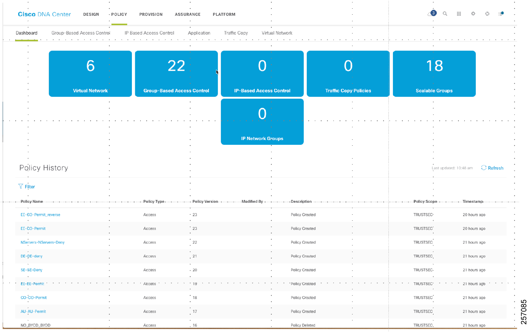
When defining custom contracts, the administrator must carefully consider the applications and ports that are needed to be allowed for the application to work properly and also filter the other protocols that are not needed for an endpoint and the application server.
User and Device Profiles in Extended Enterprise
This section describes how policy is designed in the Extended Enterprise design. As explained in The Rationale for Securing the Extended Enterprise Network, as we allow different types of users using different endpoints to access the network in the Extended Enterprise, the risk of these devices infecting other devices in the network must be mitigated. Policy design helps this objective by clearly defining the roles of the users and providing access only to those services that their business requires. The Cisco DNA Center helps customers to convert business requirements into a consistent policy that could be applied throughout the enterprise.
Table 10 is a table of users that we have created as an example that illustrates the key concept and also shows the power of the Cisco DNA Center in orchestrating this policy.
Defining the Security Groups
After defining the high-level policy requirements, the next step is to create SGTs. As shown below, a device profiled as “Badge Reader” belongs to the security group “Badge_Readers.” Similarly, a device profiled as a “Security Camera” belongs to the security group “Security_Camera.” These groups are created to show an example of how a network administrator can group devices based on the type of profile. By grouping devices based on function, we can design a security policy based on the assigned groups.
Note: The SGT table that we show below applies to both fabric and non-fabric deployments. In fabric deployments, a device can belong to a particular VN and it is prefixed by VN. It is just a name and there is no specific meaning in attaching the VN prefix.
Defining Group-Based Access Control Policies
After defining the scalable groups, the next step is to define group-based access control policies in the Cisco DNA Center. Table 12 shows an example of these policies. For instance, the intersection of security camera and badge reader is “No,” which means that communication between them is prohibited.
Security Design Considerations for Non-Fabric Deployments
This section explains the security design for non-fabric deployments. As explained in TrustSec Overview, when designing the TrustSec policy in the Extended Enterprise, three important considerations should be taken such as defining the SGT groups, propagation method, and enforcement point.
The first step is to classify a similar set of devices into an SGT group. The group assignment is done via authentication and authorization in ISE. Endpoints are authenticated to ISE by using either 802.1x or MAB protocol. After authentication, the endpoint is authorized based on conditions and is assigned a SGT as a result. For example, all cameras are assigned an SGT value 5 and all contractors are assigned an SGT value of 7. In our design, we have wired endpoints and wireless endpoints; therefore, an employee is assigned the same tag if they are connected by either wired or wireless access. See Securing the Wired and Wireless Network Access for more details on SGT assignment.
Figure 17 SGT Assignment to Different End Points
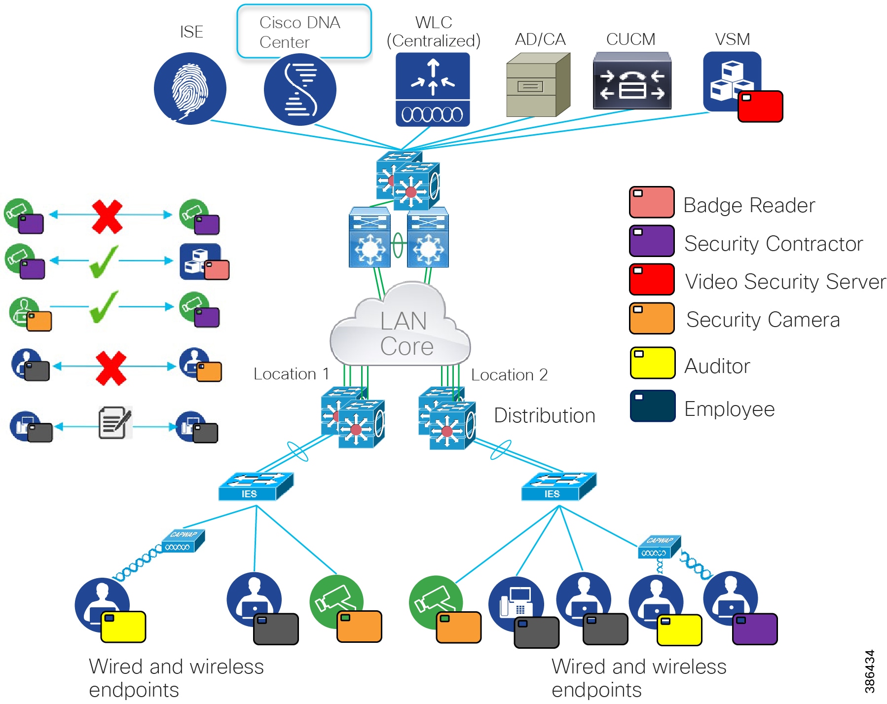
The second consideration is how to propagate the SGT tag information in the network. In this design, we have chosen to use SXP as the means to send SGT information from source to destination for the following reasons:
■![]() Certain IE switches do not support inline tagging. To understand the Cisco TrustSec capabilities for IE switches, please refer to the Cisco TrustSec 6.4 Platform Capability Matrix at the following URL:
Certain IE switches do not support inline tagging. To understand the Cisco TrustSec capabilities for IE switches, please refer to the Cisco TrustSec 6.4 Platform Capability Matrix at the following URL:
–![]() https://www.cisco.com/c/dam/en/us/solutions/collateral/enterprise-networks/trustsec/trustsec-6-0-platform-capability-matrix.pdf
https://www.cisco.com/c/dam/en/us/solutions/collateral/enterprise-networks/trustsec/trustsec-6-0-platform-capability-matrix.pdf
–![]() All the IE switches can assign an SGT value to an endpoint attached to the access layer switch.
All the IE switches can assign an SGT value to an endpoint attached to the access layer switch.
■![]() In this design, all the endpoints are authenticated to ISE by using either 802.1x or the MAB protocol. Therefore, ISE derives all the binding information through the RADIUS session between the networking devices and ISE.
In this design, all the endpoints are authenticated to ISE by using either 802.1x or the MAB protocol. Therefore, ISE derives all the binding information through the RADIUS session between the networking devices and ISE.
■![]() ISE can propagate this binding information to any enforcement point in the network. The advantage of this method is consistent delivery of SGT to IP mapping information to any enforcement point in the network. In this design, the SXP tunnel established between ISE and the distribution switch allows a distribution switch to receive binding information from ISE, as shown in Figure 18.
ISE can propagate this binding information to any enforcement point in the network. The advantage of this method is consistent delivery of SGT to IP mapping information to any enforcement point in the network. In this design, the SXP tunnel established between ISE and the distribution switch allows a distribution switch to receive binding information from ISE, as shown in Figure 18.
Figure 18 SXP Tunnel Information between ISE and the Distribution Switch
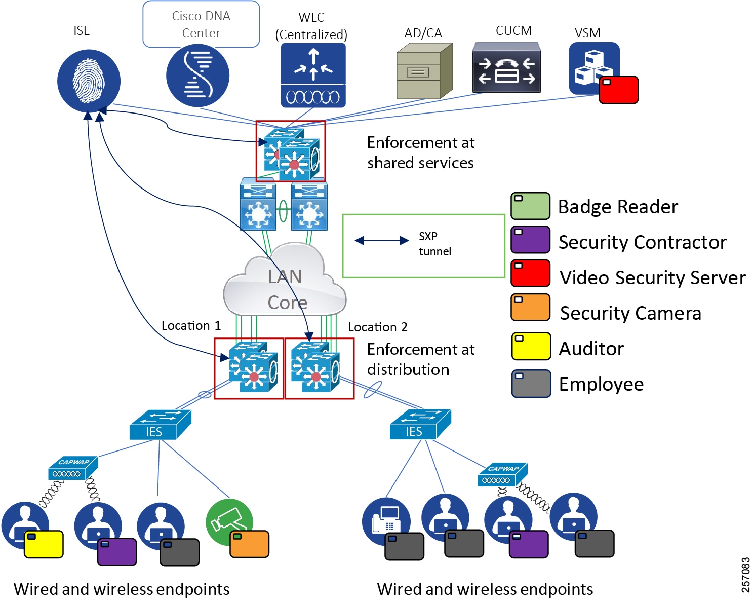
The third consideration is to choose an enforcement point. In the Extended Enterprise design, we have chosen the distribution switch as an enforcement point for these reasons:
■![]() When a network device is defined in ISE for TrustSec policy enforcement, as the network device learns mapping information for an SGT, it will communicate with ISE to get the policies associated with that SGT as a destination. SGACLs downloaded to routers and switches consume resources, and numerous SGTs with their associated policies may lead to heavy memory usage in routers and Ternary Content Addressable Memory (TCAM) exhaustion in switches. Ultimately, some SGACLs may not be installed.
When a network device is defined in ISE for TrustSec policy enforcement, as the network device learns mapping information for an SGT, it will communicate with ISE to get the policies associated with that SGT as a destination. SGACLs downloaded to routers and switches consume resources, and numerous SGTs with their associated policies may lead to heavy memory usage in routers and Ternary Content Addressable Memory (TCAM) exhaustion in switches. Ultimately, some SGACLs may not be installed.
■![]() Network devices have well-defined limits as to the number of IP to SGT mappings they can store. These mappings will consume memory as the numbers of mappings increase. If the supported numbers are exceeded, mappings will not be installed in memory and as a result, policies specific to those mappings will not be enforced.
Network devices have well-defined limits as to the number of IP to SGT mappings they can store. These mappings will consume memory as the numbers of mappings increase. If the supported numbers are exceeded, mappings will not be installed in memory and as a result, policies specific to those mappings will not be enforced.
■![]() The distribution switch in our Extended Enterprise design has enough TCAM resources to support a large SGT to IP binding information table. However, some of the IE switches in the Extended Enterprise don't support enforcement capability, which limits enforcing at the access layer. Thus, our design classifies at the access layer switch and enforces policy at the distribution switch.
The distribution switch in our Extended Enterprise design has enough TCAM resources to support a large SGT to IP binding information table. However, some of the IE switches in the Extended Enterprise don't support enforcement capability, which limits enforcing at the access layer. Thus, our design classifies at the access layer switch and enforces policy at the distribution switch.
For wireless traffic, enforcement happens on the shared services switch. Traffic from endpoints is encapsulated on CAPWAP tunnel terminating at the WLC. Configurations are detailed in the Extended Enterprise Implementation Guide for Non-Fabric deployment with Cisco DNA Center. The WLC forwards the wireless packets to the shared services switch for authorization policy enforcement. The switch gets IP-SGT mapping and authorization policy from ISE and enforces policy based on the source and destination IP-SGT. This applies to east-west and north-source traffic in both directions. Security enforcement for Internet traffic is done by security firewall.
Figure 19 Enforcement Point in Extended Enterprise Networks
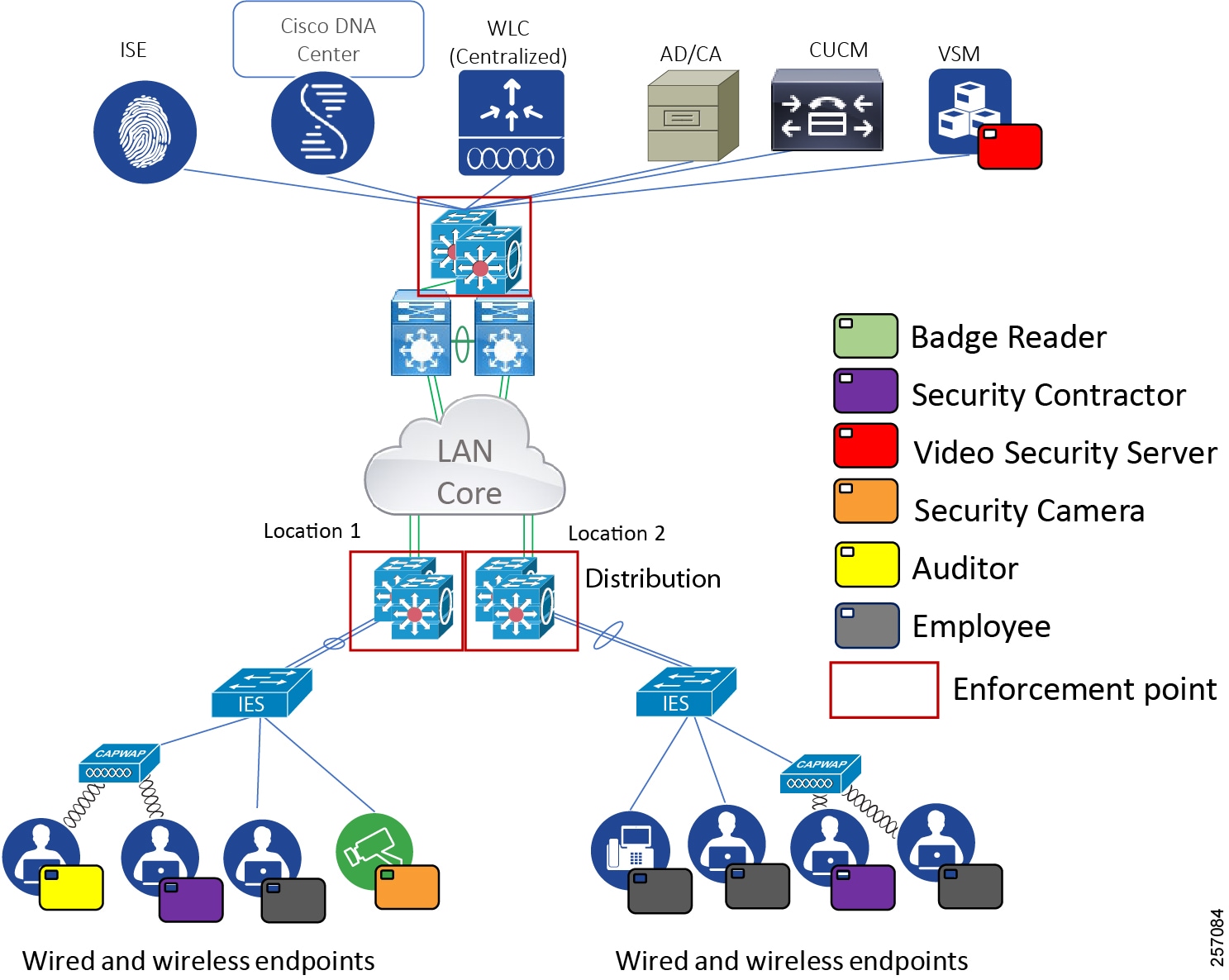
Securing the Wired and Wireless Network Access
In an enterprise deployment, we assume that a mix of wired and wireless users are accessing the network. In the non-fabric deployment all the devices connected either physically or wirelessly must be authenticated to ISE. The authentication of endpoints typically happens by the 802.1x protocol. However, certain endpoints such as printers and scanners may not support the 802.1x protocol. In that scenario, the access layer switch does authentication by using the MAB protocol. After successful authentication, the session is checked against an authorization policy, which consists of several rules created in ISE. The end result of the authorization policy could be a VLAN, SGT, dACL, or other elements that could be used to enforce network policy.
This section explains the different traffic flows that could happen in an Extended Enterprise network and how to secure wired and wireless endpoints.
Extended Enterprise Traffic Flows
Three types of traffic flows exist in an Extended Enterprise network:
■![]() Traffic among the peers in the Extended Enterprise network, which is known as east-west communication (Figure 20).
Traffic among the peers in the Extended Enterprise network, which is known as east-west communication (Figure 20).
■![]() Traffic between a server in a shared service zone to an endpoint in the Extended Enterprise, which is known as north-south communication (Figure 21).
Traffic between a server in a shared service zone to an endpoint in the Extended Enterprise, which is known as north-south communication (Figure 21).
■![]() Traffic among the wireless endpoints in an Extended Enterprise network (Figure 22).
Traffic among the wireless endpoints in an Extended Enterprise network (Figure 22).
Figure 20 East-West Traffic Flow in an Extended Enterprise Network
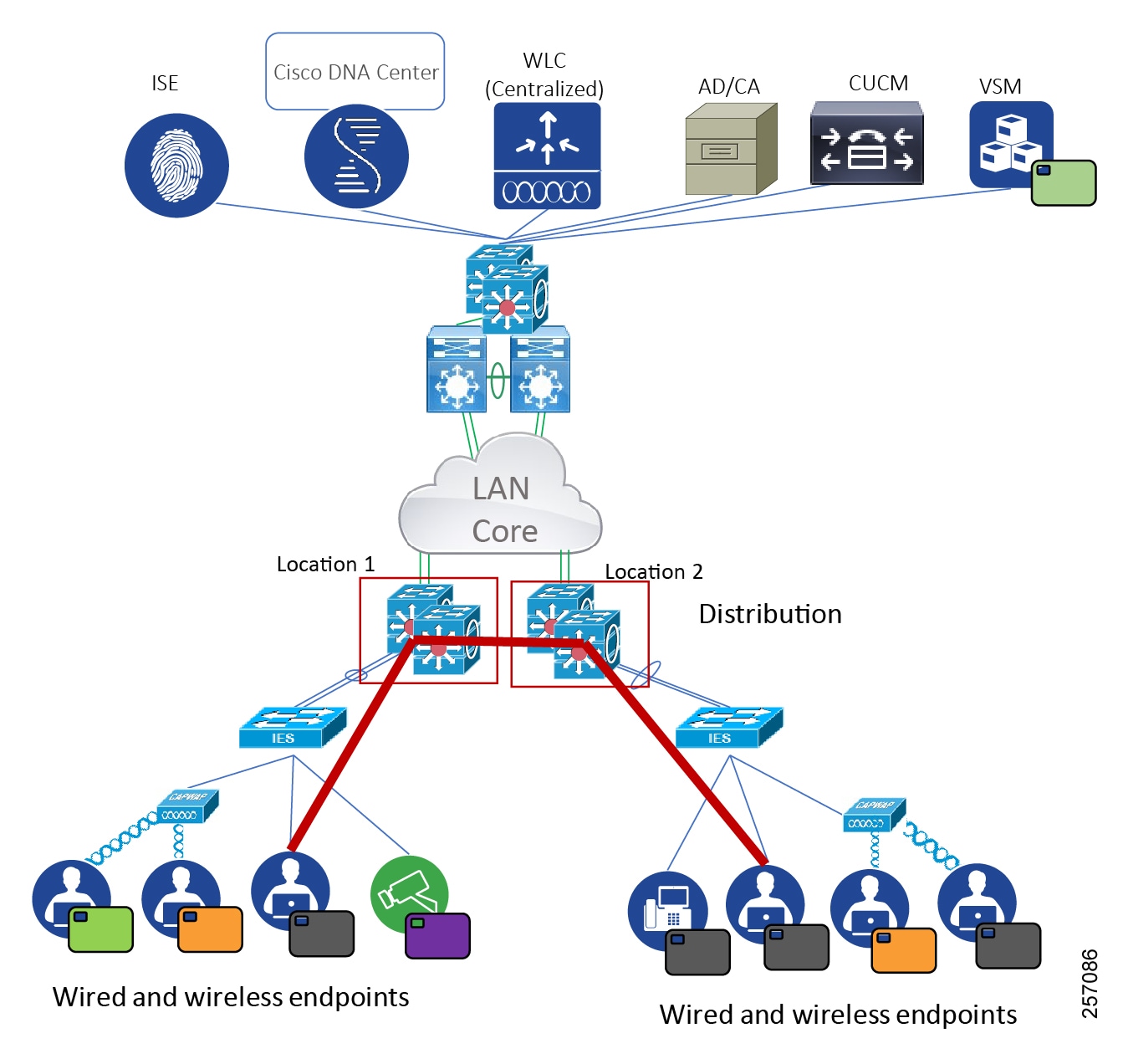
Figure 21 North-South Traffic Flow in an Extended Enterprise Network
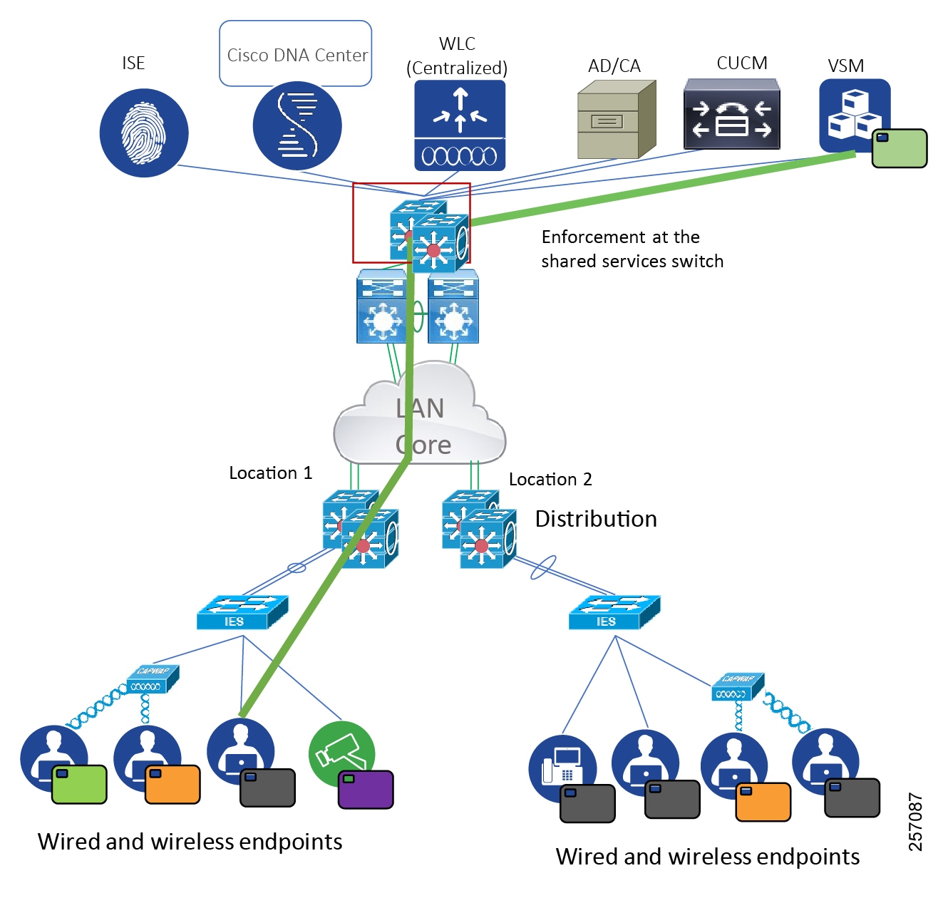
Figure 22 Traffic Flow among Wireless Peers in the Extended Enterprise Network
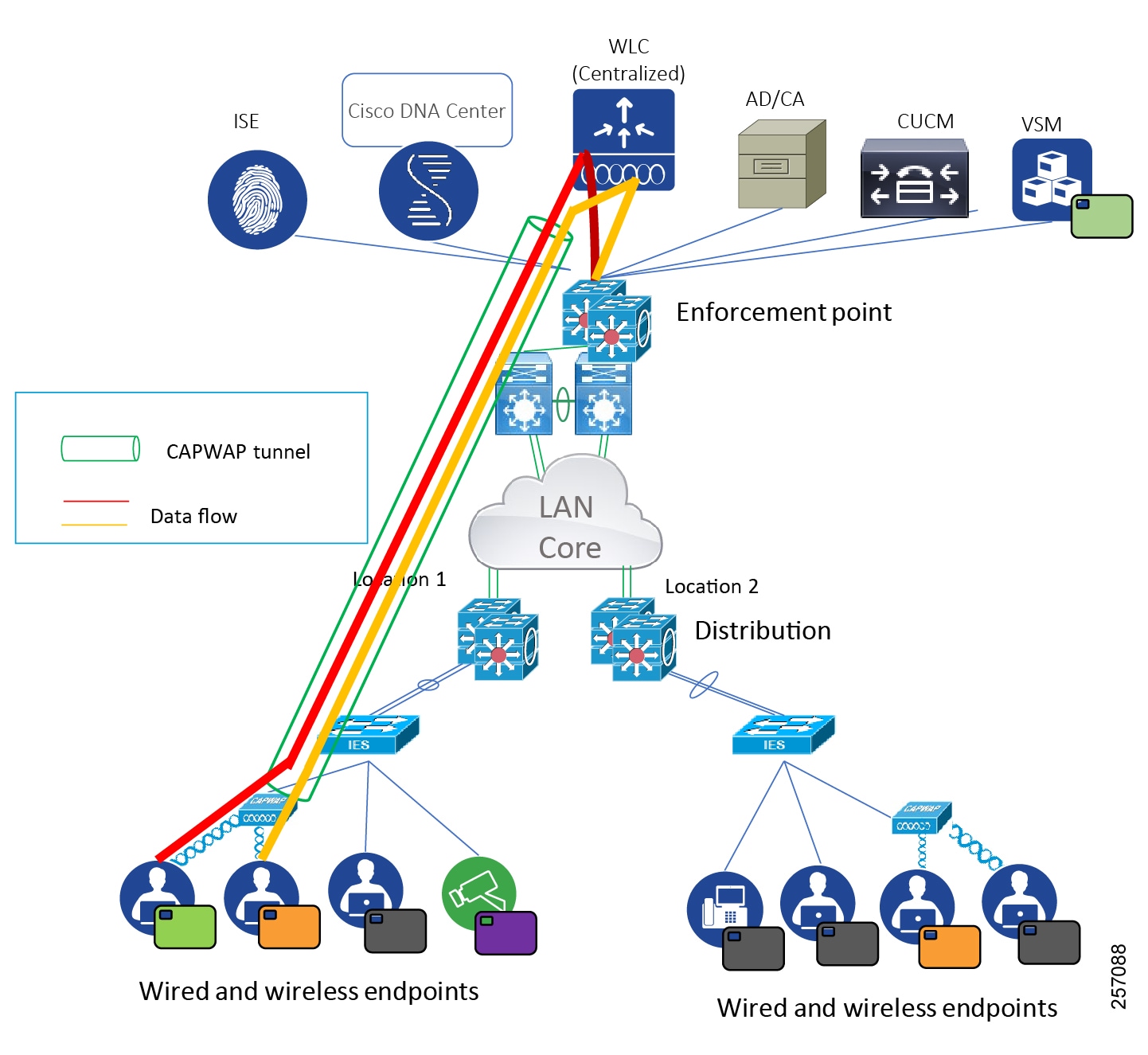
Securing Wireless Access Endpoints
Wireless devices should connect to the network infrastructure securely where possible. In an enterprise environment, you should configure WLANs to support Wi-Fi Protected Access 2 (WPA2), sometimes referred to as WPA Enterprise, with AES-CCMP encryption and 802.1x authentication of devices. 802.1x authentication requires an authentication, authorization, and accounting (AAA) server (such as ISE) that provides centralized policy-based management and control for end users accessing the wireless network.
The AAA server will implement the RADIUS protocol between itself and the WLC. Authentication of end users is accomplished via an Extensible Authentication Protocol (EAP) session between the wireless device and the AAA server. The EAP session is transported via RADIUS between the WLC and the AAA server. Depending upon the capabilities of the wireless device, the capabilities of the AAA server, and the security requirements of the organization, multiple variants of EAP, such as PEAP and EAP-TLS, may be implemented. PEAP makes use of standard user credentials (username and password) for authentication. EAP-TLS makes use of digital certificates for authentication. It is strongly recommended that you deploy redundant AAA servers for high availability if one or more servers become temporarily unavailable. Often the AAA server is configured to reference an external directory or data store such as Microsoft Active Directory (AD). This allows the network administrator to leverage existing AD credentials instead of duplicating them within the AAA server. This can also be extended to provide role-based access control (RBAC) for end users through the use of AD groups.
Securing the Wired Endpoints Supporting 802.1x
During 802.1x authentication, the switch or the client can initiate authentication. The switch can be configured to initiate authentication when the link state changes or periodically as long as the port remains up and unauthenticated. The switch sends an EAP-request frame to the client to request its identity. Upon receipt of the frame, the client responds with an EAP-response/identity frame. However, if, during boot-up, the client does not receive an EAP-request/identity frame from the switch, the client can initiate authentication by sending an EAPOL-start frame, which prompts the switch to request the client identity.
When the client supplies its identity, the switch begins its role as the intermediary, passing EAP frames between the client and the authentication server until authentication succeeds or fails. If the authentication succeeds, the switch port becomes authorized. If the authentication fails, authentication can be retried, the port might be assigned to a VLAN that provides limited services, or network access is not granted. In the Extended Enterprise design, we have provided a default tag for which minimal access is granted to the user.
Securing Wired Endpoints That Do Not Support 802.1x
Certain wired endpoints don't support 802.1x protocol. When such an endpoint connects to the access layer switch, the switch sends the authentication server (ISE) a RADIUS-access/request frame with a username and password based on the MAC address. If authorization succeeds, the switch grants the client access to the network.
In order to authorize endpoints that don't support authentication in the Extended Enterprise non-fabric design, the Cisco ISE profiling feature provides visibility and classification of the endpoints connected to the network. Using MAC addresses as the unique identifier, ISE collects various attributes for each network endpoint to build an internal endpoint database. ISE collects this information by different probes such as DHCP, HTTP, RADIUS, Simple Network Management Protocol (SNMP), AD, NetFlow, DHCPSPAN, and Platform Exchange Grid (pxGrid). After collecting endpoint information, ISE begins the classification process, matching the collected attributes to pre-built or user-defined conditions, which are then correlated to an extensive library of profiles. These profiles include a wide range of device types, including mobile clients (such as Apple iPads, Android tablets, and Blackberry phones), desktop operating systems (such as Microsoft Windows, Mac OS, and Linux), and numerous non-user systems such as printers, phones, cameras, and game consoles.
In addition, access layer switches provide visibility with the Cisco device sensor feature. The device sensor is used to gather raw endpoint data from network devices, which helps complete the device profile. A device with sensor capability gathers endpoint information from network devices using protocols such as Cisco Discovery Protocol (CDP), LLDP, and DHCP, subject to statically configured filters, and makes this information available to its registered clients in the context of an access session. The clients of the device sensor feature could be internal clients or external clients. In the Extended Enterprise design, the ISE analyzer will use the RADIUS accounting to retrieve additional endpoint data.
Key design considerations for visibility of the endpoints and networking devices include the following:
■![]() The visibility of the device should work dynamically whenever a device is attached to the network, removed from the network, or replaced with a different type of a device. For example, an attacker could replace an authenticated device and make use of the privileges given to the previous endpoint. In that scenario, the network must be able to detect a change and dynamically apply a new policy without any manual intervention.
The visibility of the device should work dynamically whenever a device is attached to the network, removed from the network, or replaced with a different type of a device. For example, an attacker could replace an authenticated device and make use of the privileges given to the previous endpoint. In that scenario, the network must be able to detect a change and dynamically apply a new policy without any manual intervention.
■![]() The device attributes such model, vendor, version, serial number, and other relevant information must be obtained by the network whenever an end device is connected. It is recommended not to deploy an endpoint that does not provide the device identification attributes when queried by the networking device. These attributes are critical for designing a secure network and access policy.
The device attributes such model, vendor, version, serial number, and other relevant information must be obtained by the network whenever an end device is connected. It is recommended not to deploy an endpoint that does not provide the device identification attributes when queried by the networking device. These attributes are critical for designing a secure network and access policy.
■![]() The administrator must have visibility into devices present in the network, and every networking device attached to the network must be authorized and provisioned. This requirement is critical to avoid the addition of rogue devices in a network. For example, a rogue AP deployed successfully in Extended Enterprise may act as a man-in-the-middle to intercept communication in the network.
The administrator must have visibility into devices present in the network, and every networking device attached to the network must be authorized and provisioned. This requirement is critical to avoid the addition of rogue devices in a network. For example, a rogue AP deployed successfully in Extended Enterprise may act as a man-in-the-middle to intercept communication in the network.
Security Design Considerations for SD-Access Deployments
This section discusses how to design and deploy a security policy over a fabric network architecture. Fabric technology allows a physical network to host multiple VNs. VNs, which are overlay networks that exchange routing and control plane information, provide programmability based on the business intent of the customer. VNs provide the implicit segmentation of the network traffic. Cross-VN traffic is denied by default.
■![]() Figure 7 highlights the different roles of devices that are part of the SD-Access fabric network topology, such as: border nodes, edge nodes, extended nodes, and shared services that were explained previously in SD-Access Overview.
Figure 7 highlights the different roles of devices that are part of the SD-Access fabric network topology, such as: border nodes, edge nodes, extended nodes, and shared services that were explained previously in SD-Access Overview.
Macro-Segmentation in SD-Access
As shown in Figure 23, we have designed the end devices to be either part of the building VN or employee VN. This assignment is to classify devices based on their role in the network. The building VN consists of devices that perform IoT functions, such as security cameras, badge readers, and respective servers that manage these end devices. The employee VN consists of devices that are typically used in an enterprise network such as laptops, mobile devices, and their respective servers.
In this section, we discuss how to design and deploy a network security policy over a fabric network. Before we delve into Cisco TrustSec, it is important to define two types of segmentation that happen in the fabric network: macro-segmentation and micro-segmentation. Macro-segmentation is the inherent property of VNs, meaning, traffic that belongs to a VN is implicitly not allowed to communicate with any other traffic belong to a different VN. When communication between VNs is needed, it can be enabled by route leaking at the fusion router located outside the fabric domain. This property is similar to how the Cisco ASA firewall controls traffic between different security zones. Figure 23 depicts how different end devices and shared services are assigned to different VNs.
Figure 23 VN Assignment in the Extended Enterprise Network
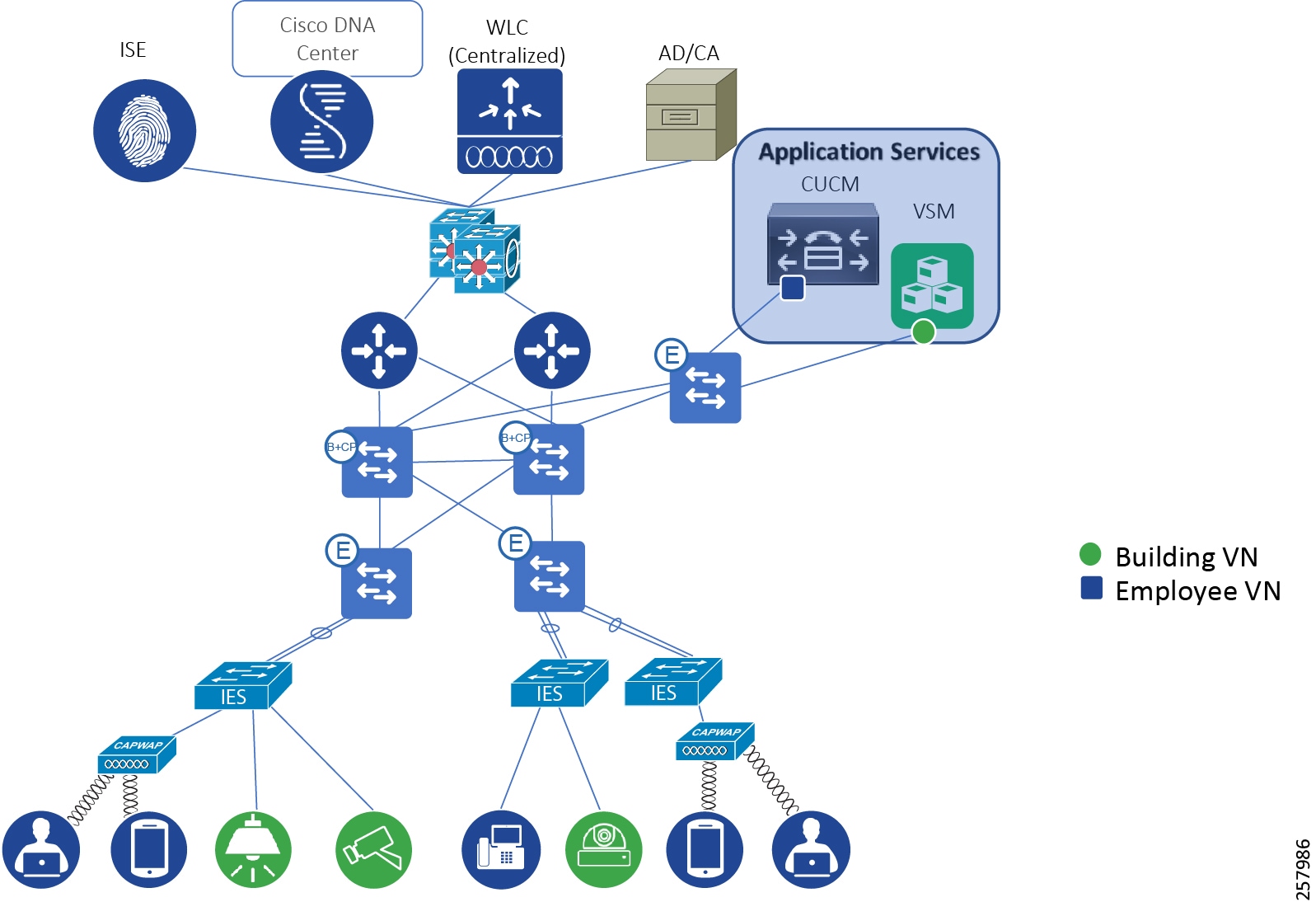
Table 13 describes the device type and its VN assignment, which we created as an example. Each end device is physically or wirelessly connected to either the extended node or the edge node.
The SGT assignment depends on where the end device is connected, which we will explain in a later section. Macro-segmentation, due to the policy of VNs, denies access from the employee to the camera because they belong to different VNs, but it allows access from the contractor laptop to the camera because they belong to same VN. In contrast, if an employee using a laptop attempts to communicate with application services, communication will be denied.
Micro-Segmentation in SD-Access
Micro-segmentation is a process of restricting communication within a particular VN. We will explain micro-segmentation for each VN we have defined. Micro segmentation enables SGACL based policy enforcement across different source and destinations.
Micro segmentation is a network segmentation method within a VN domain. It restricts communication between endpoints of the same VN.
Table 14 and Table 15 summarize the policy enforcement points for different source and destinations of traffic. The cell value shows the location of policy enforcement. For example, cell 2x2 in Table 14 shows ✓ (Policy Extended Node), this indicates policy is applied to traffic from source “Policy Extended Node 1” destined to “Policy Extended Node 1", enforcement point is “Policy Extended Node”. Another example, cell 2x2 in Table 15 shows X, this indicates no policy enforcement for traffic from a host connected to “Extended Node 1” to a destination host connected to the same “Extended Node 1".
We consider two scenarios: 1) Network with exclusive PEN (NO-STATIC-SGT scenario) 2) Network with mixed Extended and Policy Extended Nodes (STATIC-SGT scenario):
■![]() NO-STATIC-SGT scenario—Network with exclusive Policy Extended Nodes—In this scenario static SGT is configured only for the application servers. Application servers are placed in an exclusive application server subnet, thus it does not impact client enforcement. The policy enforcement for this scenario is shown in Table 14.
NO-STATIC-SGT scenario—Network with exclusive Policy Extended Nodes—In this scenario static SGT is configured only for the application servers. Application servers are placed in an exclusive application server subnet, thus it does not impact client enforcement. The policy enforcement for this scenario is shown in Table 14.
■![]() STATIC-SGT scenario—Network with mixed Extended and Policy Extended Nodes—This scenario applies to the SGTs that are common to clients across EN and PEN. In case of clients connected to EN and application servers, static SGT mapping is configured to enable micro segmentation. Static VLAN-SGT mapping is pushed to FE. FE also learns EN/PEN client IP addresses in its device tracking database. Thus, policy enforcement happens at the FE for all southbound traffic. The policy enforcement for this mixed EN/PEN scenario is shown in Table 15.
STATIC-SGT scenario—Network with mixed Extended and Policy Extended Nodes—This scenario applies to the SGTs that are common to clients across EN and PEN. In case of clients connected to EN and application servers, static SGT mapping is configured to enable micro segmentation. Static VLAN-SGT mapping is pushed to FE. FE also learns EN/PEN client IP addresses in its device tracking database. Thus, policy enforcement happens at the FE for all southbound traffic. The policy enforcement for this mixed EN/PEN scenario is shown in Table 15.
Note: To avoid unexpected behavior care should be taken to ensure static IP-SGT mapping for endpoints connected to EN and dynamic IP-SGT mapping for endpoints connected to PEN should be identical.
√ (FE2) |
√ (Remote FE3) |
√ (Application Services FE4) |
||||
√ (PEN5) |
||||||
|
|
√ (PEN6) |
√ (FE7) |
√ (Remote FE8) |
√ (Application Services FE9) |
||
|
|
Micro-Segmentation for the Building VN
The building VN consists of devices such as security cameras, video cameras, badge readers, and a video security server. Apart from the video security server, all other devices belonging to the building VN connect to the extended node/policy extended node in this design. Upon 802.1x/MAB based successful authentication any wired device connected to the extended node/policy extended node can be dynamically assigned a unique VLAN and SGT tag as shown in Figure 24.
Figure 24 SGT Assignment for the Building VN
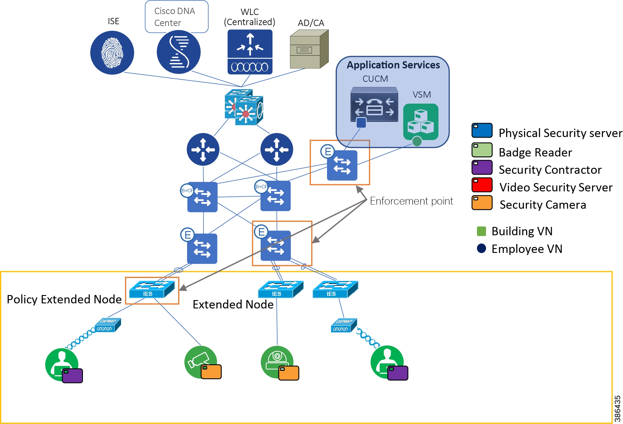
As shown in Figure 24, end devices attached to the extended node/policy extend node and servers residing in the shared services block that are part of the building VN are marked green for better depiction. This section discusses how we are assigning SGTs to all the devices that are part of the building VN. Both for wired and for wireless users, SGT assignment is done dynamically. Application servers are limited in number, they are allocated IP-addresses from specific IP-Pools. Thus, static SGT assignment is preferred for the Application servers. ISE profiling and dynamic SGT tags assignment for wireless endpoints is explained in Securing Wireless Access Endpoints. Refer to SD-Access Extended Node and SD-Access Policy Extended Nodes for dynamic SGT allocation for wired endpoints.
The only user profile that we have in the building VN is security contractor. The security contractor can be connected to the extended node/policy extended node using either wired or wireless access. Security contractor is assigned an SGT tag dynamically upon authentication.
The servers are located in the application services zone. The servers used in this design are the physical security server and the security video server. The cameras need to communicate with security video server which manages them. Similarity, the security contractor needs to communicate with the cameras and their respective servers.
As explained in Extended Enterprise Traffic Flows, east-west or north-south communication flows are happening in the Extended Enterprise network. This traffic is enforced based on the security policy defined in the ISE. One of the benefits of using SD-Access over the traditional campus design is the ability of the SD-Access network to transport the SGTs natively across the fabric. Therefore, in SD-Access, we can enforce the policy closer to the destination node. In contrast, the traditional campus designs required SXP tunnels to transport SGTs because not all network devices support the SGT in-line tagging capability. We do not have that limitation in the SD-Access network.
When a device attached to the extended node communicates with a server in the shared services block, then that communication can be enforced at the edge node closer to the shared services block. Similarly, when an end device like the camera is trying to communicate with another camera attached to another extended node, then that communication is enforced at the edge node closer to the extended node, and in case of destination endpoint connected to policy extended node, enforcement happens at the destination policy extended node as. All these scenarios are depicted in Figure 24.
Figure 25 illustrates the security group policy that we have designed in ISE for the Extended Enterprise network.
Figure 25 Security Policy Matrix for Building VN
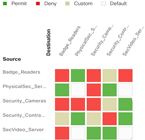
As depicted in Figure 25, east-west communication is more restricted to help enhance security. The risk of not restricting east-west communication is that an infected end device could scan, discover, and propagate malware to the rest of the devices in the network.
Micro-Segmentation for the Employee VN
This section discusses the design considerations for designing micro-segmentation for the end devices and the servers belonging to the employee VN. As described in the Figure 26, the employee VN consists of devices such as laptops, tablets, and cameras, but the critical point is that these end devices are connecting to the Extended Enterprise network from non-carpeted spaces, such as a parking lot. IE switches configured as extended nodes provide network access in such areas.
Figure 26 SGT Assignment for the Devices Belonging to the Employee VN
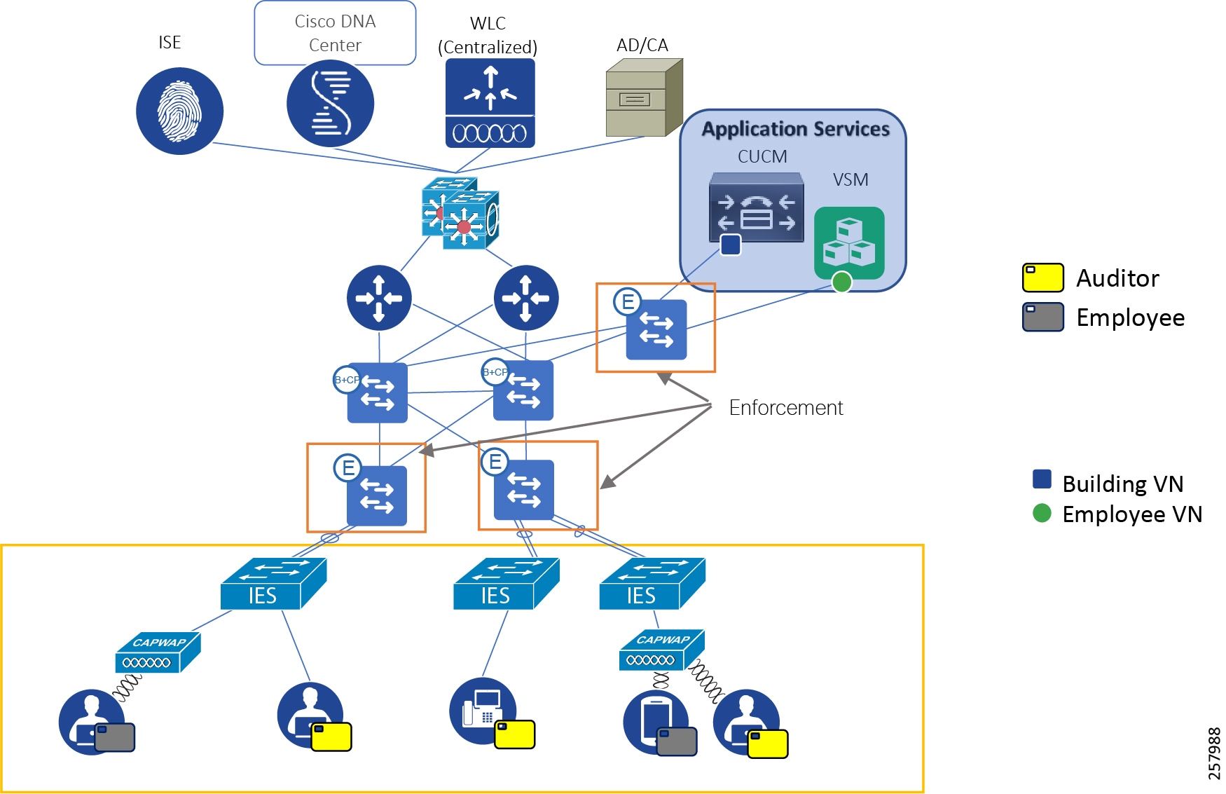
As depicted in Figure 26, all the devices and the servers belonging to the employee VN are marked with the color blue. The SGTs are assigned based on the role of the device, and ISE pushes the security policy to the enforcement node closest to the destination. Figure 27 depicts the security policy design for the device belonging to the employee VN.
Figure 27 Security Policy for the Devices Belonging to the Employee VN
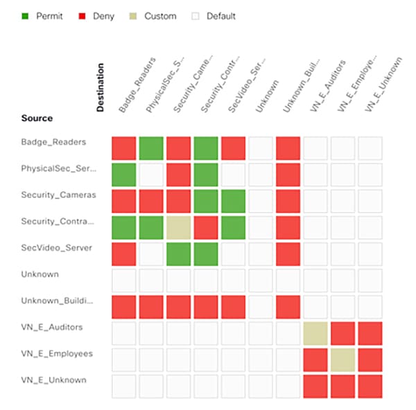
Similar to the strategy we have followed in building VN, we have controlled east-west communication to protect the network from malware propagation. Employee communication is restricted with a custom contract that allows media for phone and video calls.
Security Implementation Differences Between Fabric and Non-Fabric Deployments
In this section, we will discuss the key differences on how security is implemented in the fabric and non-fabric deployments.
Network Connectivity
In a fabric deployment, the entire network is not reachable to an end device. The end device can only connect to any end device in the same VN, without any application of security policy. In a non-fabric deployment, an end device can theoretically reach every other end device in the network.
End Devices Profiling
In a non-fabric deployment, ISE profiles all the end devices, connected physically or wirelessly. Similarly, in a fabric deployment, ISE can profile end devices connected using wired or wireless access on successful authentication. For wired users in fabric deployment, the endpoint can be connected to either extended node or policy extended node and accordingly the enforcement point varies.
SGT Transport
In a multi-fabric deployment with SD-Access transit, tags are natively transported across the network, and this inherent feature makes it easier for operational technology (OT) and IT engineers to apply the security policy. However, in the case of multi-fabric deployment with IP transit and non-fabric deployments, the tags are transported using an SXP tunnel, and this requirement needs additional manual configuration.
Network Policy Enforcement
In the non-fabric deployment, policy enforcement is done at the distribution switch because of incompatibility on some IE switches for SGT enforcement. In a non-fabric deployment, there is no such constraint, as all the switches that are part of the SD-Access fabric can enforce the policy.
Managing Device Software Images
Software image management is crucial for security implementations. Timely upgrades can protect the network against vulnerabilities. IT teams may need to upgrade the software image on networking endpoints, such as APs, switches, and routers, to address these requirements:
■![]() Make use of new desired features
Make use of new desired features
■![]() Patch systems to address security vulnerabilities
Patch systems to address security vulnerabilities
■![]() Standardize images among devices to maintain consistency
Standardize images among devices to maintain consistency
■![]() Address end-of-life notifications
Address end-of-life notifications
The Cisco DNA Center provides a software image management (SWIM) process that controls the consistency of image versions and configurations across your network. It speeds and simplifies the deployment of new software images and patches. Pre- and post-checks help ensure that no adverse effects from an upgrade occur. This is an easy to way to build a central repository of software images and apply them to devices. Administrators can mark software images as golden for a device family, allowing them to upgrade devices to the software image and patch versions that are in compliance with the golden versions defined in the repository.
Cisco DNA Center SWIM functionality provides:
■![]() Flexible and granular organization of software images and image add-ons.
Flexible and granular organization of software images and image add-ons.
■![]() Automated device auditing to determine compliance with defined image standards.
Automated device auditing to determine compliance with defined image standards.
■![]() An upgrade process that applies the standards and separates the distribution and activation tasks.
An upgrade process that applies the standards and separates the distribution and activation tasks.
To obtain more information about Cisco DNA Center updating software images, please refer to Cisco DNA Center software upgrade training at the following URL:
Extended Enterprise QoS Policy Design
This section covers Extended Enterprise QoS design details such as QoS considerations, QoS strategy, design steps, and recommendations for traffic classification and marking. This section is included for reference, but was not validated in this CVD.
Extended Enterprise QoS Design Considerations
This section describes the various design considerations for a QoS policy in the Extended Enterprise network:
■![]() Classification and Marking at the ingress should be applied to all traffic types in the entire network hierarchy, regardless of available bandwidth and expected traffic.
Classification and Marking at the ingress should be applied to all traffic types in the entire network hierarchy, regardless of available bandwidth and expected traffic.
■![]() Police traffic by defining QoS exceed policy.
Police traffic by defining QoS exceed policy.
■![]() Classify IoT use case traffic into well-defined buckets and provide QoS treatment both in terms of bandwidth and priority. If distinction is possible, IoT control traffic needs to get priority similar to network control traffic and IoT management traffic similar to network management/telemetry data. If distinction is not possible, classify all IoT traffic similar to network control traffic with well-defined priority and bandwidth. However, it is preferable not to mix IoT traffic with network control traffic, rather keep separate queue for IoT traffic.
Classify IoT use case traffic into well-defined buckets and provide QoS treatment both in terms of bandwidth and priority. If distinction is possible, IoT control traffic needs to get priority similar to network control traffic and IoT management traffic similar to network management/telemetry data. If distinction is not possible, classify all IoT traffic similar to network control traffic with well-defined priority and bandwidth. However, it is preferable not to mix IoT traffic with network control traffic, rather keep separate queue for IoT traffic.
■![]() Limit total strict priority queuing traffic (LLQ) to 33% of link capacity, to bound application response time of non-priority applications.
Limit total strict priority queuing traffic (LLQ) to 33% of link capacity, to bound application response time of non-priority applications.
■![]() Select only desired applications and corresponding application sets from the NBAR2 library. Most of the enterprise apps can be found in NBAR2 library.
Select only desired applications and corresponding application sets from the NBAR2 library. Most of the enterprise apps can be found in NBAR2 library.
Note: NBAR application classification is applicable only to nodes in access role.
■![]() Custom applications may be defined when source marking is not done. Based on destination “Server IP/Port or URL.”
Custom applications may be defined when source marking is not done. Based on destination “Server IP/Port or URL.”
■![]() DNA Center application policy does not apply to Extended Nodes.
DNA Center application policy does not apply to Extended Nodes.
Extended Enterprise QoS Design
If Cisco AutoQoS is used in the enterprise network, then Cisco AutoQoS can also be applied to Extended Enterprise network devices. All IE series switches support Cisco AutoQoS.
Alternatively, the Cisco DNA Center application policy may be used to deploy QoS across the networks. However, if the application policy from Cisco DNA Center is used, then Cisco AutoQoS needs to be disabled on all the devices. In SD-Access deployment, Extended Node devices (IE switches) are excluded from DNA Center application policy configuration, they need manual QoS configuration.
Extended Enterprise QoS follows the Enterprise QoS designs, which has the following design steps:
1.![]() Extended Enterprise services and applications are identified, for example:
Extended Enterprise services and applications are identified, for example:
2.![]() When application policy is defined by the enterprise Cisco DNA Center it can be applied to Enterprise network. If a switch defined as an access switch configurations for marking at the ingress ports and policing be applied. If a switch is tagged as core or distribution only policing configurations will be applied. On Extended Enterprise networks, distribution switches should have a corresponding distribution role on Cisco DNA Center. In SD-Access fabric deployments, it is preferable to have dedicated FE devices for connecting extended nodes to avoid role clash.
When application policy is defined by the enterprise Cisco DNA Center it can be applied to Enterprise network. If a switch defined as an access switch configurations for marking at the ingress ports and policing be applied. If a switch is tagged as core or distribution only policing configurations will be applied. On Extended Enterprise networks, distribution switches should have a corresponding distribution role on Cisco DNA Center. In SD-Access fabric deployments, it is preferable to have dedicated FE devices for connecting extended nodes to avoid role clash.
3.![]() QoS configuration on the industrial switches needs to be done directly on the device; this can be done through CLI or Cisco DNA Center templates.
QoS configuration on the industrial switches needs to be done directly on the device; this can be done through CLI or Cisco DNA Center templates.
4.![]() The classification, marking, and queuing of the enterprise should also be applied in the IE series switches. All flows and applications classified as business relevant should follow Error! Reference source not found. for classification, marking, and queuing on IE series switches. All flows classified as default are marked as DF and all flows marked as irrelevant are marked CS1.
The classification, marking, and queuing of the enterprise should also be applied in the IE series switches. All flows and applications classified as business relevant should follow Error! Reference source not found. for classification, marking, and queuing on IE series switches. All flows classified as default are marked as DF and all flows marked as irrelevant are marked CS1.
5.![]() Both IE 5000/4000 series and IE 3x00 series switches support four egress queues. However, IE 3x00 series switches support only strict priority. Thus, unconditional policing is used in the case of IE5000/IE4000 series switches for Voice and Video, whereas all categories of traffic are mapped to CBWFQ in the case of IE3x00 with reserved bandwidth.
Both IE 5000/4000 series and IE 3x00 series switches support four egress queues. However, IE 3x00 series switches support only strict priority. Thus, unconditional policing is used in the case of IE5000/IE4000 series switches for Voice and Video, whereas all categories of traffic are mapped to CBWFQ in the case of IE3x00 with reserved bandwidth.
6.![]() It is possible to use a single application policy for carpeted and non-carpeted spaces. However, if different application treatment is required as shown in Table 16, example separated policies can be created. The example shows how the default enterprise policy can be modified to meet specific needs.
It is possible to use a single application policy for carpeted and non-carpeted spaces. However, if different application treatment is required as shown in Table 16, example separated policies can be created. The example shows how the default enterprise policy can be modified to meet specific needs.
7.![]() If separate application policy for Extended Enterprise is required, it should be applied only to distribution switches dedicated to provide connectivity to non-carpeted spaces.
If separate application policy for Extended Enterprise is required, it should be applied only to distribution switches dedicated to provide connectivity to non-carpeted spaces.
All IE switches support four egress queues. The recommended queuing profile for Cisco IE4000, Cisco 4010, and Cisco 5000 access switches is shown in Table 17.
The recommended queuing profile for Cisco IE3x000 series switches is shown in Table 18.
Extended Enterprise Network Dataflows for Non-Fabric Deployments
In this CVD, we have described provisioning of network devices such as Cisco IE switches and wired and wireless endpoints such as cameras and phones. This section describes the main steps that occur in the Cisco DNA Center when an IE switch or a wireless access point is onboarded. The intent is to give the reader a comprehensive understanding of the work that occurs in the background. In this section, we also describe how wired or wireless Extended Enterprise endpoints (cameras, phones, and others) authenticate and authorize against ISE. A pictorial representation of device and client onboarding operations, different wired and wireless dataflows, and roles of different network components for non-fabric deployments is shown in this section for readers to more easily understand the design.
Non-Fabric Switch Onboarding
An Extended Enterprise switch can be onboarded either through a discovery or a PnP process. PnP is a process for onboarding a new device with ZTD with no need for any pre-staging. A pre-staged device can be discovered and added to the Cisco DNA Center-managed network with the discovery process.
PnP provisioning can be for a known (planned) or unknown device. Figure 28 depicts user steps and behind the scene automated operations that occur during the onboarding and provisioning of a network device, such as an IE switch in a non-fabric deployment.
Figure 28 Extended Enterprise Wired Device Discovery and PnP
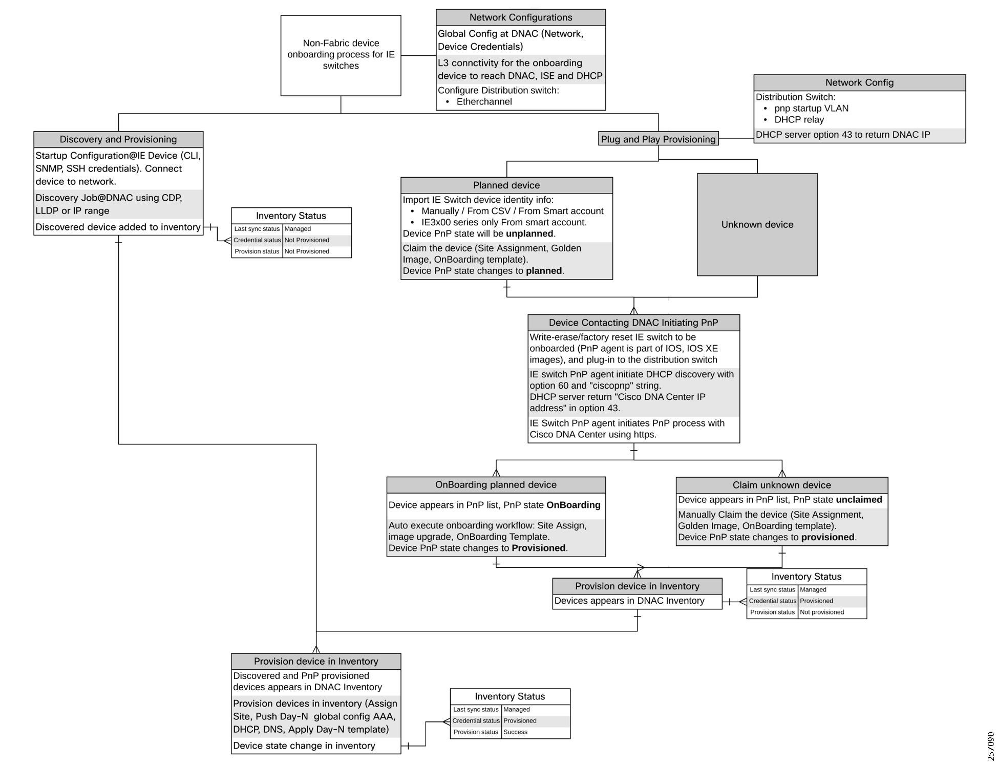
A workflow example for device onboarding and provisioning can be listed as follows:
Global Configuration in Cisco DNA Center for Device Onboarding and Provisioning
1.![]() Global configuration in Cisco DNA Center required before device onboarding:
Global configuration in Cisco DNA Center required before device onboarding:
a.![]() Network settings for ISE for network devices, ISE for Client devices, DHCP, DNS, SNMP, and NTP.
Network settings for ISE for network devices, ISE for Client devices, DHCP, DNS, SNMP, and NTP.
b.![]() Device credentials for CLI, SNMP, and Https.
Device credentials for CLI, SNMP, and Https.
2.![]() Configure DHCP relay/DHCP server in the access switch. Configure Cisco DNA Center IP address in option 43.
Configure DHCP relay/DHCP server in the access switch. Configure Cisco DNA Center IP address in option 43.
Additional Configuration for Planned Device Plug and Play Provisioning
3.![]() Upload device identity information for planned devices manually, from a CSV file, or by fetching from a Cisco Smart Account. Device identity information includes serial number, product ID, and optional stack information. The device PnP state is set to unplanned.
Upload device identity information for planned devices manually, from a CSV file, or by fetching from a Cisco Smart Account. Device identity information includes serial number, product ID, and optional stack information. The device PnP state is set to unplanned.
4.![]() Claim the device following onboarding-workflow (site assignment, golden image and onboarding template), device PnP state is moved to planned.
Claim the device following onboarding-workflow (site assignment, golden image and onboarding template), device PnP state is moved to planned.
Onboarding Device with Plug and Play
5.![]() Use the write-erase command on the PnP-compatible device to be onboarded (PnP agent is part of IOS and IOS XE images), and connect the device to the access switch with Layer 3 connectivity to the Cisco DNA Center.
Use the write-erase command on the PnP-compatible device to be onboarded (PnP agent is part of IOS and IOS XE images), and connect the device to the access switch with Layer 3 connectivity to the Cisco DNA Center.
6.![]() The PnP agent initiates DHCP discovery with option 60 and ciscopnp string and gets the Cisco DNA Center IP address in option 43. PnP agent initiates the PnP process with the Cisco DNA Center using HTTPS.
The PnP agent initiates DHCP discovery with option 60 and ciscopnp string and gets the Cisco DNA Center IP address in option 43. PnP agent initiates the PnP process with the Cisco DNA Center using HTTPS.
7.![]() The device appears in the Cisco DNA Center PnP list. If the device is an unknown device, its PnP state is set to unclaimed; if it is a planned device, the PnP state goes to onboarding.
The device appears in the Cisco DNA Center PnP list. If the device is an unknown device, its PnP state is set to unclaimed; if it is a planned device, the PnP state goes to onboarding.
8.![]() For planned devices, the onboarding workflow is initiated automatically. For unknown devices, the operator claims the device manually and follows the onboarding workflow.
For planned devices, the onboarding workflow is initiated automatically. For unknown devices, the operator claims the device manually and follows the onboarding workflow.
9.![]() On completion of onboarding, the PnP state is updated to provisioned.
On completion of onboarding, the PnP state is updated to provisioned.
10.![]() Provisioned devices appear in the Cisco DNA Center inventory, with the last sync status as managed and provision state = not provisioned.
Provisioned devices appear in the Cisco DNA Center inventory, with the last sync status as managed and provision state = not provisioned.
Onboarding a Device Using Discovery
1.![]() Repeat Steps 1 and 2 from the previous section.
Repeat Steps 1 and 2 from the previous section.
2.![]() Pre-stage the device by configuring discovery credentials on the device (CLI, SNMP, SSH, HTTPS, and NETCONF) and connect the device to the access switch with Layer 3 connectivity to Cisco DNA Center.
Pre-stage the device by configuring discovery credentials on the device (CLI, SNMP, SSH, HTTPS, and NETCONF) and connect the device to the access switch with Layer 3 connectivity to Cisco DNA Center.
3.![]() Initiate the discovery process in Cisco DNA Center choosing one of the discovery types: CDP, IP Range, or LLDP.
Initiate the discovery process in Cisco DNA Center choosing one of the discovery types: CDP, IP Range, or LLDP.
4.![]() Discovered devices added to Cisco DNA Center Inventory with last sync status as managed and provision state = not provisioned.
Discovered devices added to Cisco DNA Center Inventory with last sync status as managed and provision state = not provisioned.
Provisioning Devices in Cisco DNA Center Inventory
Provision configures AAA and DNS settings, assigns a location and optionally pushes configuration templates to device. To provision, follow the three step wizard:
1.![]() Assign a site to the device (greyed out if device is already assigned to site during PnP).
Assign a site to the device (greyed out if device is already assigned to site during PnP).
3.![]() Review and confirm. Device provision status in inventory changes to Success.
Review and confirm. Device provision status in inventory changes to Success.
Security Configuration During Onboarding Process
1.![]() In the PnP process, device credentials (username and password) are deployed by Cisco DNA Center on the device. In a discovery process, the device credentials are manually configured.
In the PnP process, device credentials (username and password) are deployed by Cisco DNA Center on the device. In a discovery process, the device credentials are manually configured.
2.![]() Cisco DNA Center pushes device identity credentials (username and password) to ISE, which matches the credentials that are pushed to the networking end device. These credentials are used by the Cisco DNA Center to authenticate itself to the networking device. Also, other credentials such as the RADIUS secret for the networking device and Cisco TrustSec (CTS) credentials are also pushed to ISE so that the networking device can communicate with ISE using those credentials when using a respective protocol.
Cisco DNA Center pushes device identity credentials (username and password) to ISE, which matches the credentials that are pushed to the networking end device. These credentials are used by the Cisco DNA Center to authenticate itself to the networking device. Also, other credentials such as the RADIUS secret for the networking device and Cisco TrustSec (CTS) credentials are also pushed to ISE so that the networking device can communicate with ISE using those credentials when using a respective protocol.
3.![]() After the device is provisioned, Cisco DNA Center authenticates the device with ISE. If ISE is not reachable (no RADIUS response), the device uses the local login credentials. If ISE is reachable, but the device does not exist in ISE or its credentials do not match the credentials configured in Cisco DNA Center, the device does not fall back to use the local login credentials. Instead, it goes into a partial collection state.
After the device is provisioned, Cisco DNA Center authenticates the device with ISE. If ISE is not reachable (no RADIUS response), the device uses the local login credentials. If ISE is reachable, but the device does not exist in ISE or its credentials do not match the credentials configured in Cisco DNA Center, the device does not fall back to use the local login credentials. Instead, it goes into a partial collection state.
Wired Device and Wired Client Onboarding and Dataflows for Non-Fabric Deployments
The following process and diagrams explain the steps needed to onboard a wired client to a non-fabric Extended Enterprise deployment including configuration steps that need to be done prior to endpoint onboarding. Startup configurations on Cisco DNA Center and ISE for device onboarding are shown in Figure 29 and explained in Step 1 through Step 7 below.
1.![]() Operator configures a policy set in ISE that specifies the conditions for authentication and authorization policies. A successful match in authentication policy allows access to the network, whereas a successful authorization policy results in downloading a policy element such as ACL, dACL, VLAN, or SGT. These policy elements aid an operator to define a network policy.
Operator configures a policy set in ISE that specifies the conditions for authentication and authorization policies. A successful match in authentication policy allows access to the network, whereas a successful authorization policy results in downloading a policy element such as ACL, dACL, VLAN, or SGT. These policy elements aid an operator to define a network policy.
2.![]() The operator defines the configuration template on DNA, which contains the AAA, RADIUS, CTS, and change of authorization (CoA) configurations, and this entire configuration template is pushed to the networking device during networking device on-boarding.
The operator defines the configuration template on DNA, which contains the AAA, RADIUS, CTS, and change of authorization (CoA) configurations, and this entire configuration template is pushed to the networking device during networking device on-boarding.
3.![]() Operator configures the group-based access policy (security policy) in the Cisco DNA Center.
Operator configures the group-based access policy (security policy) in the Cisco DNA Center.
4.![]() Cisco DNA Center automatically pushes the group-based security policy to ISE.
Cisco DNA Center automatically pushes the group-based security policy to ISE.
5.![]() ISE pushes the group-based access policy in the form of an SGACL to the distribution switch using the CTS protocol.
ISE pushes the group-based access policy in the form of an SGACL to the distribution switch using the CTS protocol.
6.![]() Operator using Cisco DNA Center enables 802.1x/MAB authentication on the access switch port.
Operator using Cisco DNA Center enables 802.1x/MAB authentication on the access switch port.
7.![]() Operator using Cisco DNA Center configures DHCP server/relay on the distribution switch.
Operator using Cisco DNA Center configures DHCP server/relay on the distribution switch.
Figure 29 Extended Enterprise Wired Device Provisioning
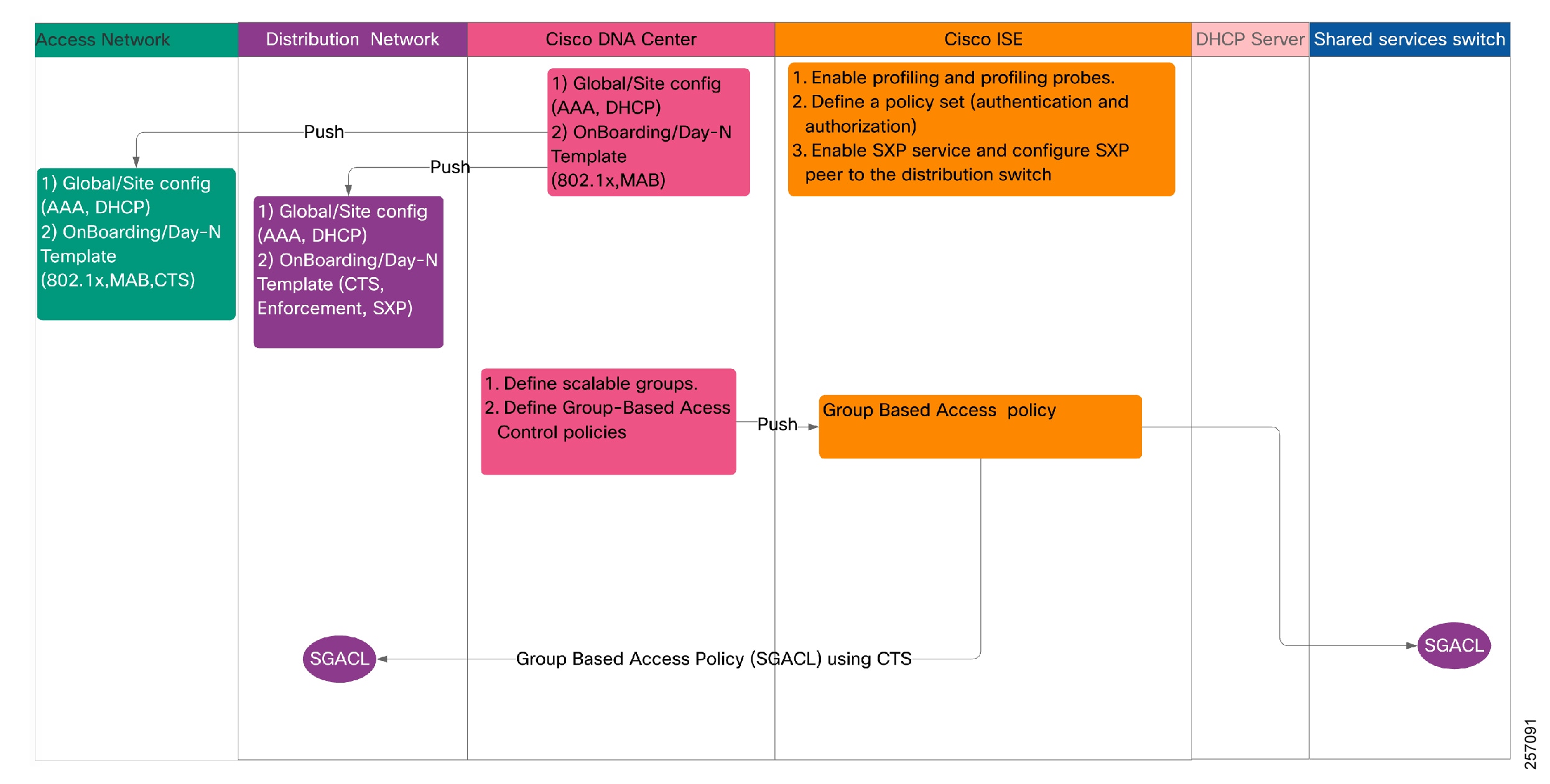
Wired client onboarding and data communication flows are shown in Figure 30 and enumerated in Step 8 through Step 17 below.
8.![]() When the 802.1x-capable wired client connects to an access layer switch, it triggers 802.1x authentication and the access switch forwards the request to ISE/AAA.
When the 802.1x-capable wired client connects to an access layer switch, it triggers 802.1x authentication and the access switch forwards the request to ISE/AAA.
9.![]() On timeout (not receiving 802.1x EAP identity response from client), the access switch initiates MAB to ISE.
On timeout (not receiving 802.1x EAP identity response from client), the access switch initiates MAB to ISE.
10.![]() ISE authenticates by profiling and allocates an SGT. The SGT is pushed to the access switch port to which the client is connected.
ISE authenticates by profiling and allocates an SGT. The SGT is pushed to the access switch port to which the client is connected.
11.![]() An 802.1x success message is sent to the client from the access switch.
An 802.1x success message is sent to the client from the access switch.
12.![]() The wired client initiates a DHCP request and receives an IP address.
The wired client initiates a DHCP request and receives an IP address.
13.![]() SXP is configured between ISE as a speaker and the distribution switch as a listener. Whenever a new SGT mapping is learned by ISE, it pushes the binding information (IP-SGT mapping) through the SXP tunnel to the distribution switch, so that the distribution switch can apply the policy.
SXP is configured between ISE as a speaker and the distribution switch as a listener. Whenever a new SGT mapping is learned by ISE, it pushes the binding information (IP-SGT mapping) through the SXP tunnel to the distribution switch, so that the distribution switch can apply the policy.
14.![]() The wired client attached to the access layer switch initiates a data packet to a destination wired endpoint.
The wired client attached to the access layer switch initiates a data packet to a destination wired endpoint.
15.![]() The distribution switch tags the packet with Source SGT. It derives the binding information for the destination-wired client from ISE using SXP protocol.
The distribution switch tags the packet with Source SGT. It derives the binding information for the destination-wired client from ISE using SXP protocol.
16.![]() The distribution switch derives a SGACL entry from ISE based on the source and destination SGTs, and then implements access control (allowed or denied).
The distribution switch derives a SGACL entry from ISE based on the source and destination SGTs, and then implements access control (allowed or denied).
17.![]() If source and destination addresses are within the same VLAN and within the same access switch, then the destination is found in the local FDB and packet is switched locally with no policy applied.
If source and destination addresses are within the same VLAN and within the same access switch, then the destination is found in the local FDB and packet is switched locally with no policy applied.
Figure 30 Extended Enterprise Wired Client Onboarding and Dataflow
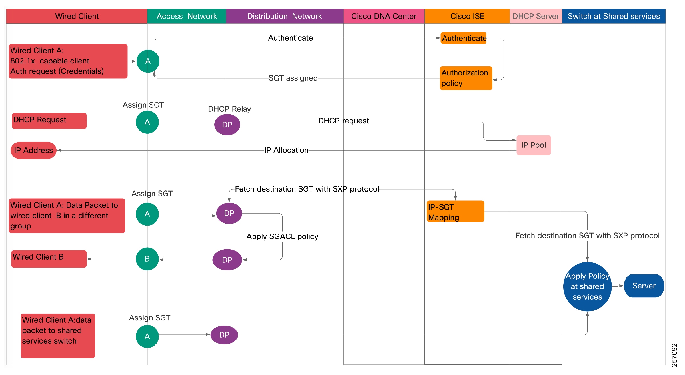
Onboarding WLAN Controller and Access Points for Non-Fabric Deployments
The following process and diagrams explain the steps needed to onboard a wireless client to a non-fabric Extended Enterprise deployment including configuration steps that need to be done prior to endpoint onboarding. Startup configurations and steps for onboarding WLC and AP are shown in Figure 31 and explained in Step 1 through Step 13 below.
1.![]() Operator provides global configurations (NW settings—AAA, DHCP, Wireless settings—SSID, WPA2 Enterprise—802.1x, RF Profile, non-fabric, central mode) are at the Cisco DNA Center.
Operator provides global configurations (NW settings—AAA, DHCP, Wireless settings—SSID, WPA2 Enterprise—802.1x, RF Profile, non-fabric, central mode) are at the Cisco DNA Center.
2.![]() Operator initiates the discovery process for WLC. On discovery, WLC is added to the Cisco DNA Center inventory.
Operator initiates the discovery process for WLC. On discovery, WLC is added to the Cisco DNA Center inventory.
3.![]() Provisioning is initiated for the WLC in the inventory (site-assignment and global-config-deploy).
Provisioning is initiated for the WLC in the inventory (site-assignment and global-config-deploy).
4.![]() Global-config pushed to WLC.
Global-config pushed to WLC.
5.![]() Operator configures a template having “AP-VLAN and enable 802.1x” at Cisco DNA Center and pushes to the enterprise access switch (AP-VLAN assigned to the port where AP is connected).
Operator configures a template having “AP-VLAN and enable 802.1x” at Cisco DNA Center and pushes to the enterprise access switch (AP-VLAN assigned to the port where AP is connected).
6.![]() If already associated, WLC pushes 802.1x credentials to AP; otherwise, the operator manually configures on AP.
If already associated, WLC pushes 802.1x credentials to AP; otherwise, the operator manually configures on AP.
7.![]() AP initiates 802.1x, access switch forwards the request to ISE.
AP initiates 802.1x, access switch forwards the request to ISE.
8.![]() ISE authenticates—Does profiling and allocates SGT; SGT is pushed to access switch port to which AP is connected.
ISE authenticates—Does profiling and allocates SGT; SGT is pushed to access switch port to which AP is connected.
9.![]() On successful authentication, AP initiates DHCP and receives WLC IP via option 43.
On successful authentication, AP initiates DHCP and receives WLC IP via option 43.
10.![]() AP establishes CAPWAP with WLC. All future communications from AP (data, control, and management) are sent through the CAPWAP to WLC and then WLC forwards it to the destination. Therefore, unlike wired communication, in this case access switch cannot do tagging and distribution switch cannot do policy enforcement.
AP establishes CAPWAP with WLC. All future communications from AP (data, control, and management) are sent through the CAPWAP to WLC and then WLC forwards it to the destination. Therefore, unlike wired communication, in this case access switch cannot do tagging and distribution switch cannot do policy enforcement.
11.![]() AP appears on Cisco DNA Center inventory and is provisioned and assigned to a site.
AP appears on Cisco DNA Center inventory and is provisioned and assigned to a site.
12.![]() Operator configures group-based access policy (security policy) in the Cisco DNA Center.
Operator configures group-based access policy (security policy) in the Cisco DNA Center.
13.![]() The Cisco DNA Center auto-pushes group-based security policy to ISE.
The Cisco DNA Center auto-pushes group-based security policy to ISE.
14.![]() ISE pushes the group-based access policy in the form of SGACL to the shared service switch using CTS protocol.
ISE pushes the group-based access policy in the form of SGACL to the shared service switch using CTS protocol.
Figure 31 Extended Enterprise Onboarding WLAN Controller and Access Points
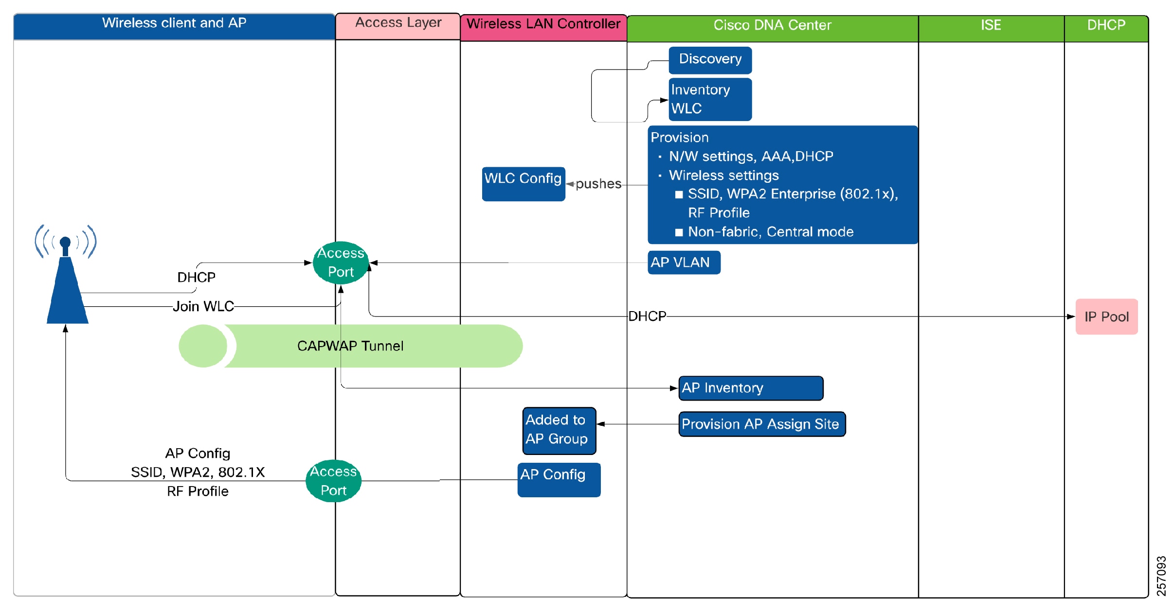
Extended Enterprise Wireless Client Onboarding and Dataflows for Non-Fabric Deployments
Wireless client onboarding and data communication flows are shown in Figure 32 and enumerated in Step 15 through Step 21 below.
15.![]() Wireless client initiates a data traffic to another wireless client either within the same SSID or in a different SSID.
Wireless client initiates a data traffic to another wireless client either within the same SSID or in a different SSID.
16.![]() Traffic is forwarded by the AP to the WLC over CAPWAP.
Traffic is forwarded by the AP to the WLC over CAPWAP.
17.![]() WLC directs the traffic to the shared services switch for authorization policy enforcement.
WLC directs the traffic to the shared services switch for authorization policy enforcement.
18.![]() Shared services switch returns the packet to WLC if authorized.
Shared services switch returns the packet to WLC if authorized.
19.![]() WLC forwards the packet to the destination client via the destination AP/
WLC forwards the packet to the destination client via the destination AP/
20.![]() The wireless client initiates a data traffic to a wired client (steps 15 and 16 are followed).
The wireless client initiates a data traffic to a wired client (steps 15 and 16 are followed).
21.![]() Shared services switch forwards the packet to destination via the wired access switch.
Shared services switch forwards the packet to destination via the wired access switch.
Steps for dataflow from wireless clients to shared services/application servers follows Step 20 to Step 21 (similar to wireless to wired dataflow) above.
Figure 32 Extended Enterprise Onboarding Wireless Client and Dataflow
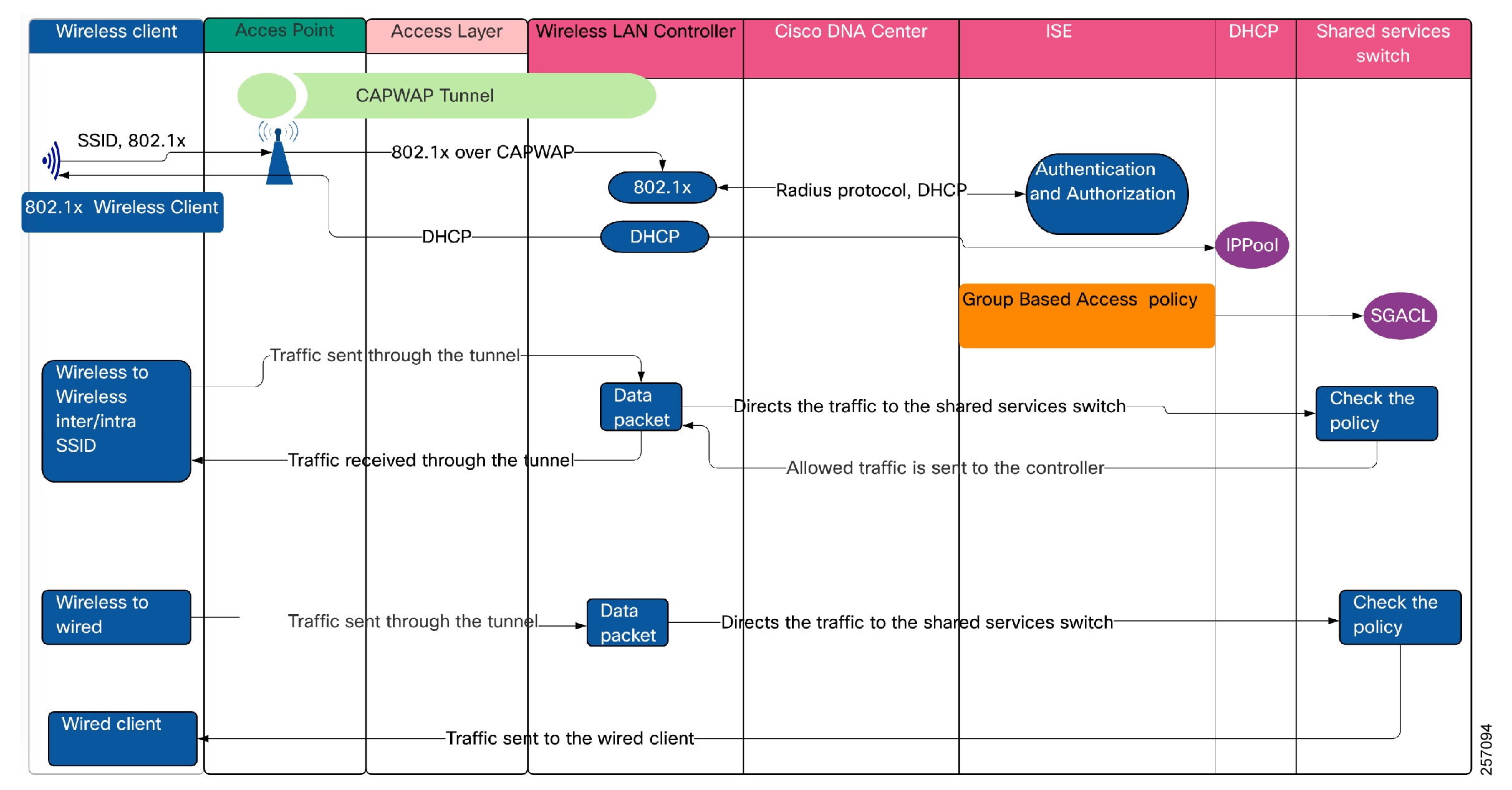
Extended Enterprise Network Dataflows for SD-Access Deployments
This section provides a step-by-step description of device and client onboarding operations for SD-Access deployments.
SD-Access Extended Node Onboarding
Onboarding of an extended node process is explained below.
■![]() Fabric site is configured with borders, control, and edge nodes.
Fabric site is configured with borders, control, and edge nodes.
■![]() IP pool for extended nodes is created and reserved for the fabric site.
IP pool for extended nodes is created and reserved for the fabric site.
■![]() IP pool is associated with INFRA_VN on fabric host onboarding.
IP pool is associated with INFRA_VN on fabric host onboarding.
■![]() DHCP pool is configured with option 43 pointing to Cisco DNA Center.
DHCP pool is configured with option 43 pointing to Cisco DNA Center.
1.![]() If the fabric global authentication template is not set to open authentication, manually create a port channel on the edge node using Cisco DNA Center.
If the fabric global authentication template is not set to open authentication, manually create a port channel on the edge node using Cisco DNA Center.
2.![]() If fabric global authentication template is set to other than open authentication, statically assign a port channel on the edge node to the extended node/policy extended node. If open authentication is configured, this step can be skipped.
If fabric global authentication template is set to other than open authentication, statically assign a port channel on the edge node to the extended node/policy extended node. If open authentication is configured, this step can be skipped.
3.![]() Connect the unconfigured IE switch a port channel member on the edge device.
Connect the unconfigured IE switch a port channel member on the edge device.
4.![]() Reload the IE switch, which will then initiate the PnP process.
Reload the IE switch, which will then initiate the PnP process.
5.![]() The IE switch becomes part of the fabric as an extended node and is assigned to the same site as the edge node.
The IE switch becomes part of the fabric as an extended node and is assigned to the same site as the edge node.
SD-Access Network Dataflow within a Fabric Site
As an example, for intra-fabric site data traffic flow, assume dataflows between a source Endpoint-A1 in Fabric Site-A and a destination Endpoint-A2 in Fabric Site-A. This is illustrated in Figure 33 and Figure 34.
Figure 33 Dataflow Within a Fabric Site and Within the Same Access Switch (Extended Node)
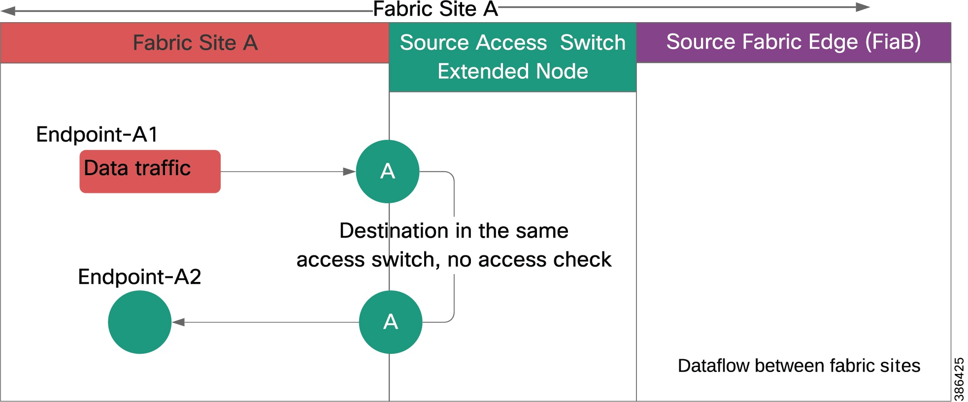
Dataflow within a fabric site and within the same access switch:
1.![]() Source Endpoint-A1 initiates a data packet.
Source Endpoint-A1 initiates a data packet.
2.![]() The IE access switch tags Service-VLAN.
The IE access switch tags Service-VLAN.
3.![]() If source and destination endpoints are in the same Service-VLAN and within the same extended node as shown in Figure 33, then the destination is found in the local Forwarding Database (FDB) and packet is switched within the Layer 2 network with no policy applied.
If source and destination endpoints are in the same Service-VLAN and within the same extended node as shown in Figure 33, then the destination is found in the local Forwarding Database (FDB) and packet is switched within the Layer 2 network with no policy applied.
4.![]() If source and destination endpoints are within the same policy extended node as shown in Figure 34, then access policy check is done by PEN consulting the SGACL policy and packet is switched within the access switch.
If source and destination endpoints are within the same policy extended node as shown in Figure 34, then access policy check is done by PEN consulting the SGACL policy and packet is switched within the access switch.
Figure 34 Dataflow Within a Fabric Site and Within the Same Access Switch (Policy Extended Node)
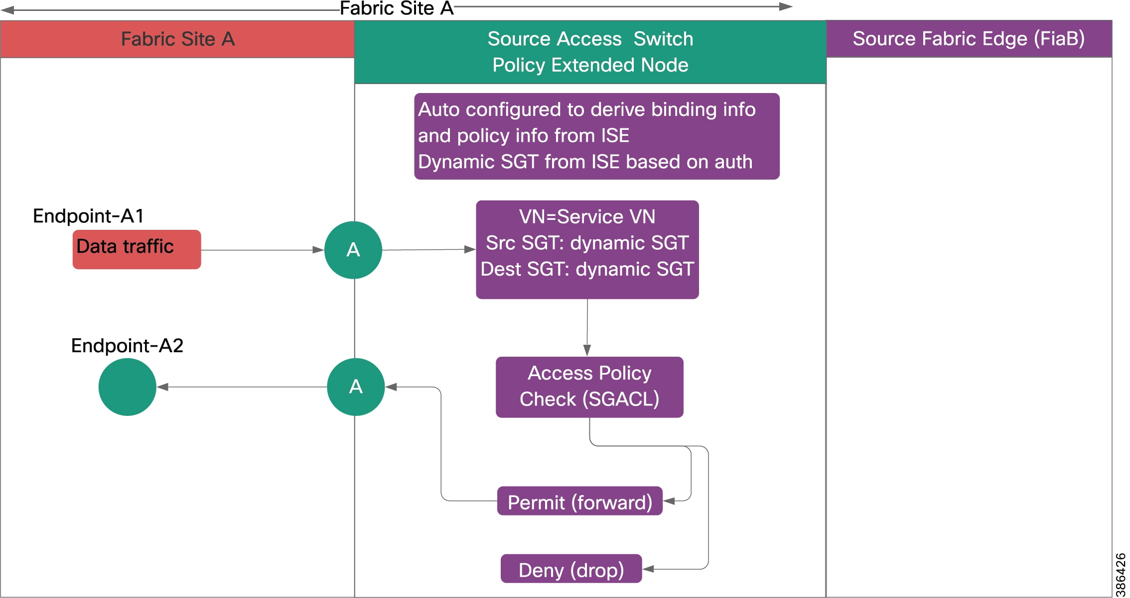
1.![]() Shown in Figure 35 and Figure 36, Policy Extended Node is auto-configured to derive binding information and policy information from ISE.
Shown in Figure 35 and Figure 36, Policy Extended Node is auto-configured to derive binding information and policy information from ISE.
2.![]() Source Endpoint is authenticated with either 802.1x or MAB.
Source Endpoint is authenticated with either 802.1x or MAB.
3.![]() Authorization policy is applied by ISE. VLAN and SGT are configured on the access port to which endpoint is connected.
Authorization policy is applied by ISE. VLAN and SGT are configured on the access port to which endpoint is connected.
4.![]() Source Endpoint-A1 connected to a policy extended node initiates a data packet.
Source Endpoint-A1 connected to a policy extended node initiates a data packet.
5.![]() Source access port tags VLAN and dynamic SGT obtained from ISE.
Source access port tags VLAN and dynamic SGT obtained from ISE.
6.![]() The packet is locally switched within the PEN after applying SGACL policy. If policy permit, forward the packet to destination access port; if policy deny, drop the packet (see Figure 35 and Figure 36).
The packet is locally switched within the PEN after applying SGACL policy. If policy permit, forward the packet to destination access port; if policy deny, drop the packet (see Figure 35 and Figure 36).
Figure 35 Dataflow within a Policy Extended Node
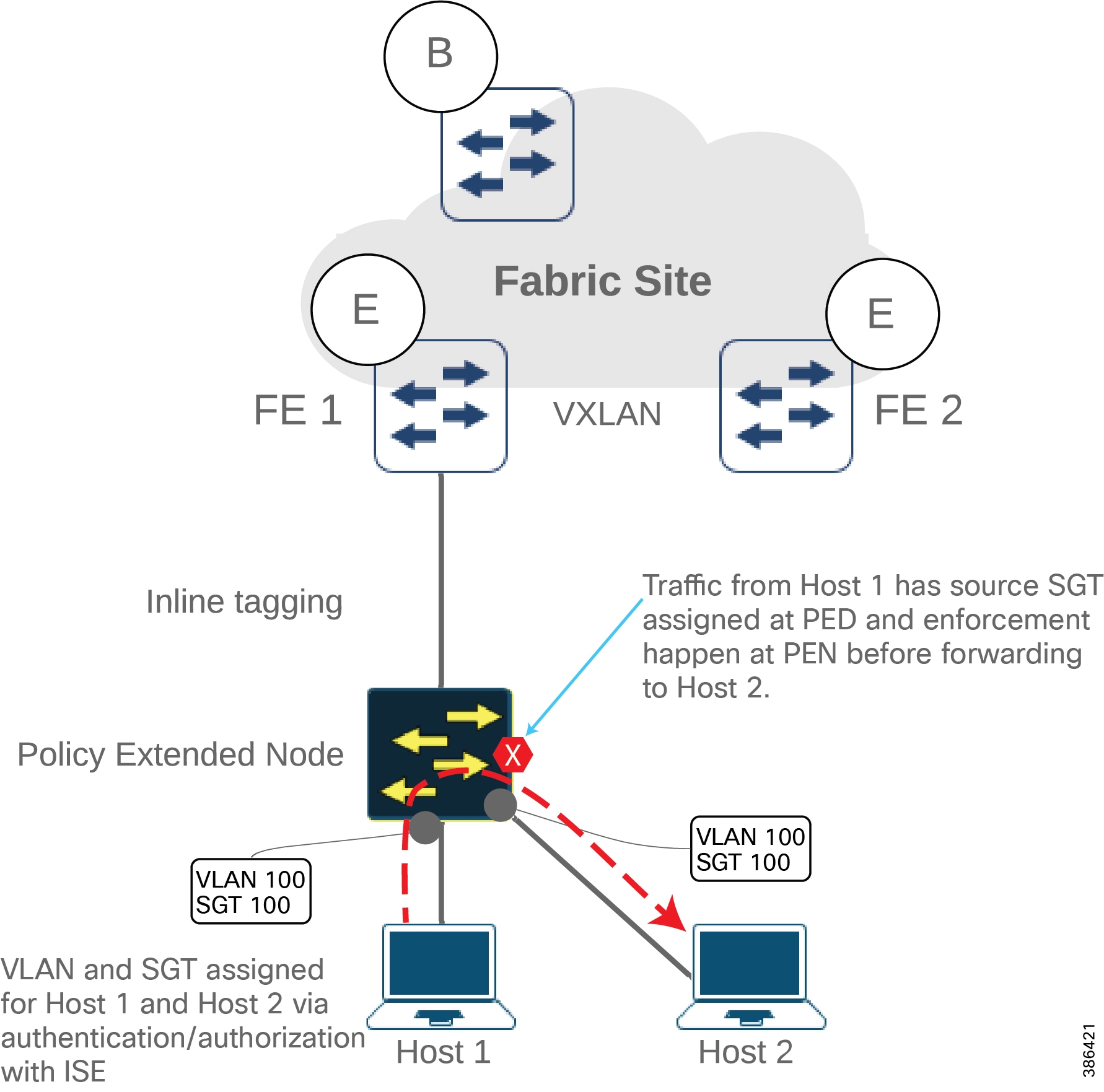
Dataflow across access switches within a fabric edge/fabric site are shown in Figure 36, Figure 37 and Figure 38.
1.![]() Source Endpoint A1 is authenticated with either 802.1x or MAB.
Source Endpoint A1 is authenticated with either 802.1x or MAB.
2.![]() On successful authentication ISE configures VLAN for source port.
On successful authentication ISE configures VLAN for source port.
3.![]() In case of STATIC-SGT scenario as described earlier, static VLAN-SGT configured at DNAC are pushed to FEs. In case of NO-STATIC-SGT scenario, dynamic SGT are pushed to PEN.
In case of STATIC-SGT scenario as described earlier, static VLAN-SGT configured at DNAC are pushed to FEs. In case of NO-STATIC-SGT scenario, dynamic SGT are pushed to PEN.
4.![]() Source Endpoint-A1 initiates a data packet.
Source Endpoint-A1 initiates a data packet.
5.![]() VLAN is tagged in case source access switch is EN as shown in Figure 33 and both VLAN and SGT are tagged in case source access switch is PEN as shown in Figure 34.
VLAN is tagged in case source access switch is EN as shown in Figure 33 and both VLAN and SGT are tagged in case source access switch is PEN as shown in Figure 34.
6.![]() When source and destination endpoints are not in the same access switch, packet is forwarded to FE.
When source and destination endpoints are not in the same access switch, packet is forwarded to FE.
7.![]() In case of STATIC-SGT scenario, policy check is done at FE as shown in Figure 36 and Figure 40 and in case of NO-STATIC-SGT scenario, policy check is done at the PEN as shown Figure 37 and Figure 39. In case destination access switch is FE, policy check is done at FE as shown in Figure 38.
In case of STATIC-SGT scenario, policy check is done at FE as shown in Figure 36 and Figure 40 and in case of NO-STATIC-SGT scenario, policy check is done at the PEN as shown Figure 37 and Figure 39. In case destination access switch is FE, policy check is done at FE as shown in Figure 38.
Figure 36 Dataflow Across Access Switches within a Fabric Edge/Fabric Site (STATIC-SGT Scenario)
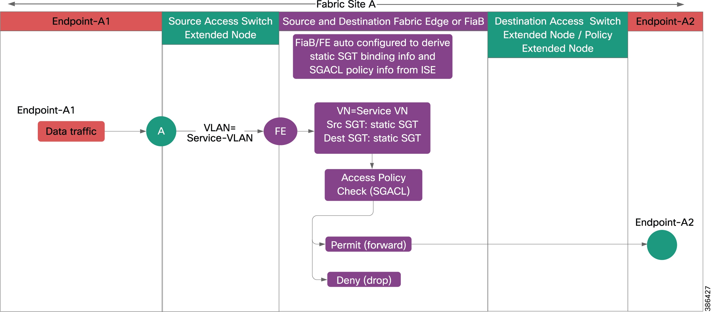
Figure 37 Dataflow Across Access Switches within a Fabric Edge/Fabric Site (NO-STATIC-SGT Scenario)
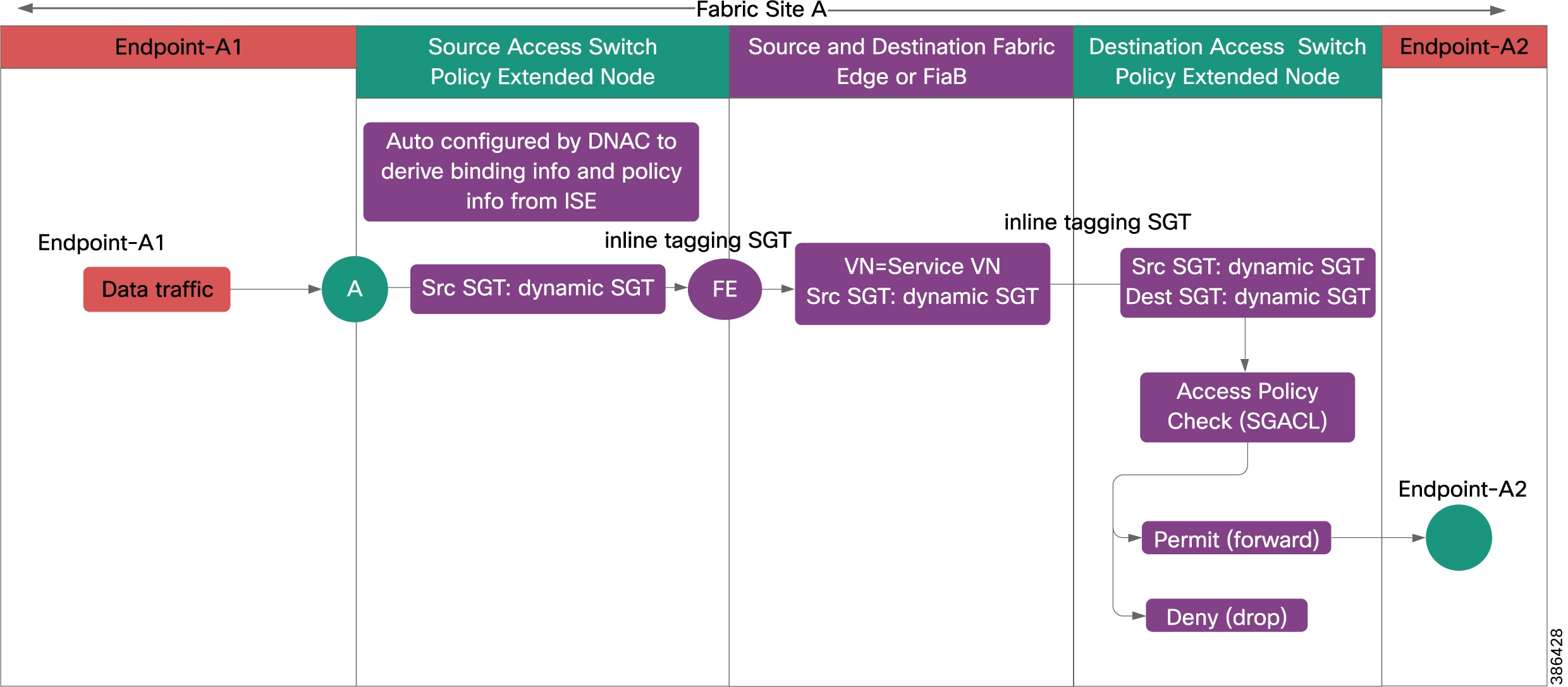
Figure 38 Dataflow within a Fabric Site Source being a Policy Extended Node
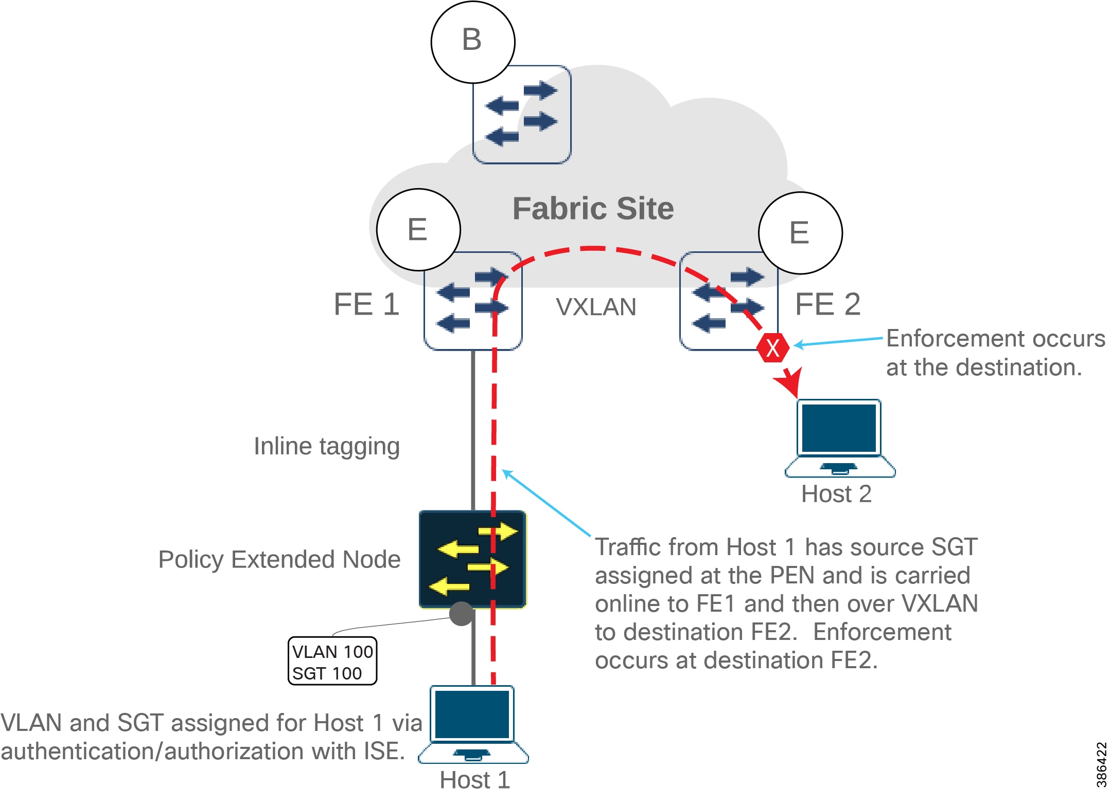
Figure 39 Dataflow within a Fabric Site (NO-STATIC-SGT Scenario) Destination being a Policy Extended Node
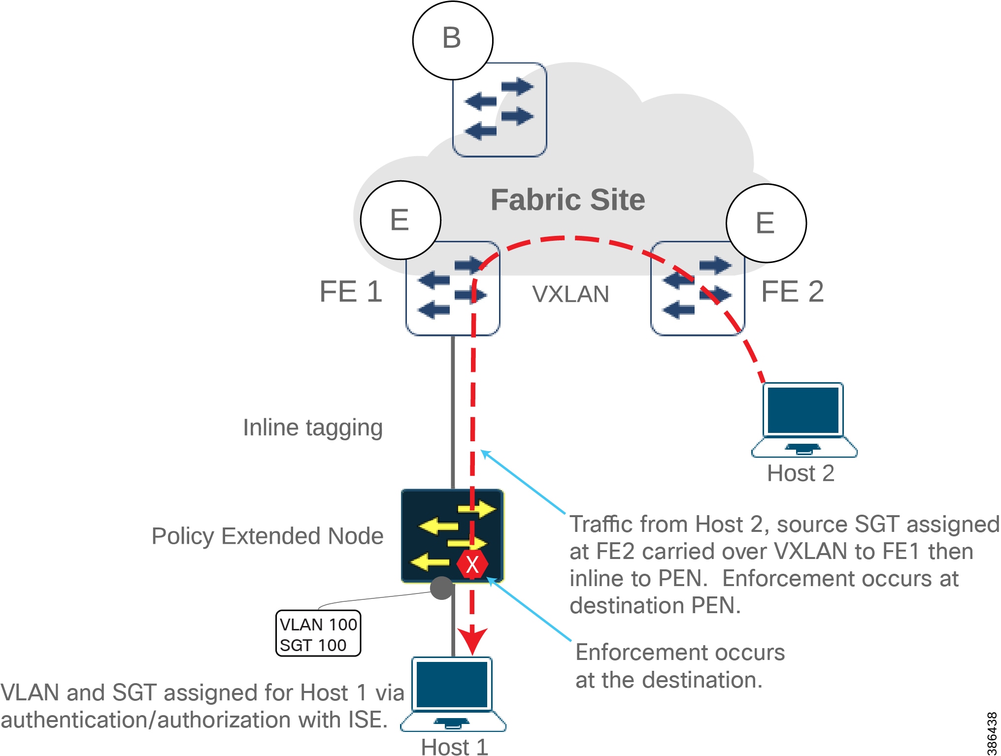
Figure 40 Dataflow within a Fabric Site (STATIC-SGT Scenario) Destination being a Policy Extended Node
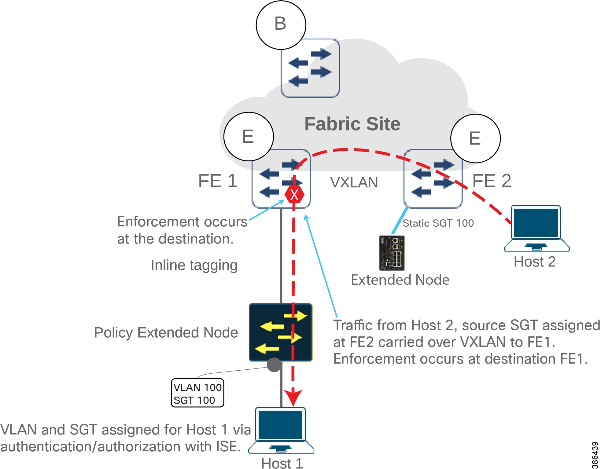
SD-Access Network Dataflow Between Fabric Sites
As an example, for the inter-fabric site data traffic flow, assume dataflows between a source Endpoint-A1 in Fabric Site A and a destination Endpoint-B1 in Fabric Site B. This is illustrated in Figure 41 and Dataflow between Hosts of Different Fabric Sites across IP-based Transit .
Figure 41 Dataflow between Hosts of Different Fabric Sites across SD-Access Transit
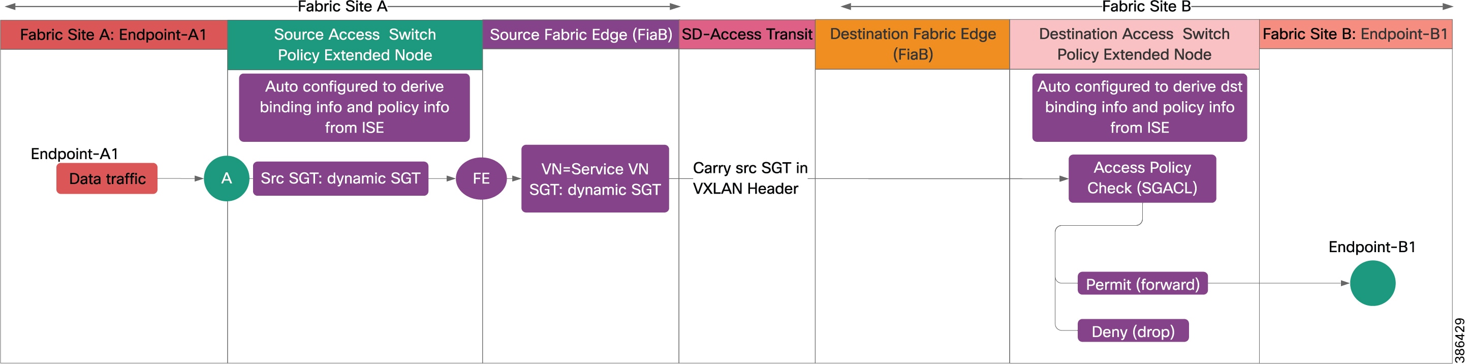
Figure 42 Dataflow between Hosts of Different Fabric Sites across IP-based Transit
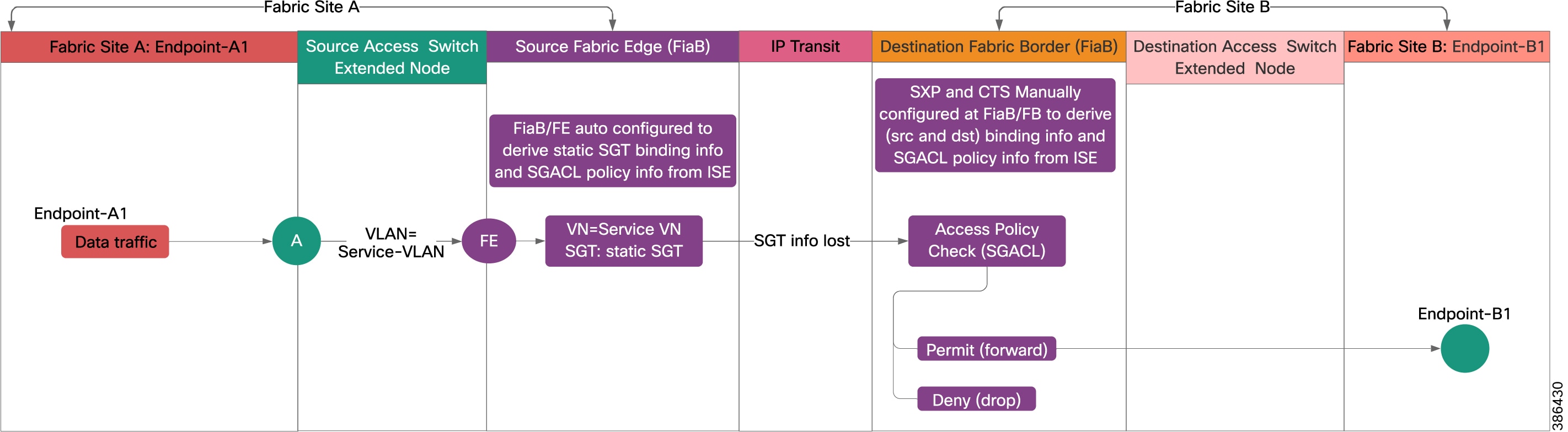
1.![]() Source Endpoint-A1 initiates a data packet.
Source Endpoint-A1 initiates a data packet.
2.![]() The IE access switch tags Service-VLAN or VLAN + SGT.
The IE access switch tags Service-VLAN or VLAN + SGT.
3.![]() Source Fabric edge maps Service-VLAN to Service-VN. Packet forwarded to destination fabric.
Source Fabric edge maps Service-VLAN to Service-VN. Packet forwarded to destination fabric.
4.![]() In case of SD-Access transit, source SGT is carried via inline tagging from source fabric edge to destination fabric edge as shown in Figure 41.
In case of SD-Access transit, source SGT is carried via inline tagging from source fabric edge to destination fabric edge as shown in Figure 41.
5.![]() In case of IP-based transit, source SGT is lost at the source fabric border. Destination fabric border derives the source SGT binding information using SXP to ISE as shown in Figure 42.
In case of IP-based transit, source SGT is lost at the source fabric border. Destination fabric border derives the source SGT binding information using SXP to ISE as shown in Figure 42.
6.![]() If destination access switch is EN, destination fabric edge derives destination SGT binding information, performs access check consulting SGACL, and takes forwarding decision. If permit, forward the packet to destination access switch; if deny, drop the packet. Destination access switch forwards the packet to destination Endpoint-B1.
If destination access switch is EN, destination fabric edge derives destination SGT binding information, performs access check consulting SGACL, and takes forwarding decision. If permit, forward the packet to destination access switch; if deny, drop the packet. Destination access switch forwards the packet to destination Endpoint-B1.
7.![]() If destination access switch is PEN, it gets destination SGT binding information from ISE, performs access check consulting SGACL, and takes forwarding decision. If permit, forward the packet to destination endpoint; if deny, drop the packet.
If destination access switch is PEN, it gets destination SGT binding information from ISE, performs access check consulting SGACL, and takes forwarding decision. If permit, forward the packet to destination endpoint; if deny, drop the packet.
Wired Client Onboarding and Dataflows for Endpoints Connected to Extended Nodes
Onboarding a wired endpoint to an extended node/policy extended node was explained before. The process is explained in this section.
■![]() IP pool for endpoints is created and reserved for the fabric site.
IP pool for endpoints is created and reserved for the fabric site.
■![]() Virtual Network for endpoint overlay is created and SGTs are assigned.
Virtual Network for endpoint overlay is created and SGTs are assigned.
■![]() IP pool is associated with virtual network on fabric host onboarding and SGT is selected.
IP pool is associated with virtual network on fabric host onboarding and SGT is selected.
■![]() DHCP pool is configured for endpoints and reachable from network overlay.
DHCP pool is configured for endpoints and reachable from network overlay.
1.![]() Extended node port is dynamically assigned to IP pool on Cisco DNA Center.
Extended node port is dynamically assigned to IP pool on Cisco DNA Center.
2.![]() Endpoint is connected to the port and obtains DHCP IP address.
Endpoint is connected to the port and obtains DHCP IP address.
3.![]() When the endpoint traffic flows through edge node, packet gets assigned SGT based on the IP pool of the user.
When the endpoint traffic flows through edge node, packet gets assigned SGT based on the IP pool of the user.
SD-Access Wireless Dataflows
All steps involved in onboarding APs and endpoints on SD-Access deployment are depicted in the SD-Access Wireless Design and Deployment Guide. For details, refer to the following URL:
■![]() https://www.cisco.com/c/en/us/td/docs/wireless/controller/technotes/8-5/b_SD_Access_Wireless_Deployment_Guide.html#concept_683A128194E04DE2A1AB5FC96B488E32
https://www.cisco.com/c/en/us/td/docs/wireless/controller/technotes/8-5/b_SD_Access_Wireless_Deployment_Guide.html#concept_683A128194E04DE2A1AB5FC96B488E32
Extended Enterprise High Availability
High availability (HA) will ensure uninterrupted service. Therefore, HA is needed for every critical component and link in the overall network. This section discusses HA design for the entire solution.
Extended Enterprise Wired Access and Distribution Layer Redundancy
High availability is provided at distribution layer by configuring Cisco StackWise-480. Two or more distribution switches are configured for redundancy. The distribution switches configure the EtherChannel to connect two links to access switch. If any of the distribution switches or links fail, the operation will continue with no interruption.
Extended Enterprise Wireless Access and Distribution Layer Redundancy
A common way to provide redundancy at the wireless access layer is to do dense deployment of APs or overlap-based deployment. You can ensure each location is covered by more than one nearby AP (preferably three nearby APs should cover an area).
For high availability of WLC, deploy a pair of controllers in High Availability Stateful Switchover (HA SSO) configuration, as shown in Figure 43. The HA SSO model provides box-to-box redundancy with one controller in active state and a second controller in hot standby state. Link Aggregation (LAG) is configured at WLC since LACP and PAgP are not supported by the controller.
In a Cisco DNA Center-managed network, WLC HA SSO pair configuration is done by the Cisco DNA Center. The Cisco Campus-LAN-WAN Design Guide provide details for configuring redundancy for WLC.
Figure 43 WLC HA SSO Link Aggregation

Shared Services Switches Redundancy
All shared services switches are provided with redundancy. Depending on the type of the switch and connected devices, StackWise-480 or EtherChannel or Flex Link or LAG are configured for redundancy.
Shared Services High Availability
Cisco DNA Center redundancy is provided by clustering three Cisco DNA Center appliances together. Clustering provides both a sharing of resources and features, as well as helps enable HA and scalability. The Cisco DNA Center supports a single-host or three-host cluster configuration. The three-host cluster provides both software and hardware high availability. The single-host cluster only provides software HA; it does not provide hardware HA. Thus, we recommend three-host cluster configuration to be used for Extended Enterprise. Detailed configuration is provided in the Cisco DNA Center Administration Guide at the following URL:
■![]() https://www.cisco.com/c/en/us/td/docs/cloud-systems-management/network-automation-and-management/dna-center/1-2-10/admin/guide/b_dnac_admin_guide_1_2_10.html
https://www.cisco.com/c/en/us/td/docs/cloud-systems-management/network-automation-and-management/dna-center/1-2-10/admin/guide/b_dnac_admin_guide_1_2_10.html
Application Servers Redundancy
Depending on the provisioning, UCS server level redundancy and/or application level redundancy can be configured for each application server.
Extended Enterprise Scale and Dimensioning
This section illustrates scaling considerations and available options at different layers of the network and provides steps for computing dimensions for an Extended Enterprise network deployment.
Extended Enterprise Solution Scaling Considerations
The Extended Enterprise solution consists of the Extended Enterprise access layer, enterprise distribution, core layer, and the data center layer.
Tech Tip: Please refer to appropriate Cisco documentation to compute the scaling details of enterprise layers, which is not part of the scope of this document. The Cisco enterprise layers are usually highly scalable; therefore, with appropriate usage/expansion of network devices one can accommodate the Extended Enterprise traffic.
In this section, we cover the scaling details for access layer and data center layer. The data center layer is a shared service between Enterprise and Extended Enterprise. Here the overall capacity of the data center layers is shown; this section, in conjunction with Extended Enterprise Solution Components for Non-Fabric Deployments and Extended Enterprise Solution Components for Cisco SD-Access Deployments, can help derive the possible scalability of shared services.
Extended Enterprise Access Layer Scaling
The Cisco Industrial Ethernet Portfolio has various features suiting different deployment criteria. The access layer switches shown in Table 19 are modular in size with various form factors, port sizes, and features. Thus, the Cisco Extended Enterprise access layer is highly scalable from a very small to very large size with a suitable quantity of IE switches and outdoor APs. A comparison of IE switches is given in Table 19 as a reference to select suitable models based on the deployment need.
|
|
|
|
|
|
|
|
|
|
|
|
|
|
|
|
|
|
|
|
|
|
|
|
|
|
|
|
|
|
|
|
|
|
|
|
|
|
|
|
|
|
|
|
|
|
|
|
|
|
|
|
|
|
|
|
|
|
|
|
|
|
|
|
|
|
|
|
|
|
|
|
|
|
|
|
|
|
|
|
|
|
|
|
|
|
|
|
|
|
|
|
|
|
|
|
|
|
|
|
|
10.IE3300 expansion modules can be plugged with IE3400 base switch. However, this combination prevents support for advanced security feature such as SGT/SGACL on the IE3400 base switch. |
The Software-Defined Access Design Guide provides scale guidance for fabric deployment other than extended nodes. Refer to the following URL:
■![]() https://cvddocs.com/fw/250-prime
https://cvddocs.com/fw/250-prime
The Cisco DNA Center scaling computation and hardware specification is given in the respective Cisco DNA Center Data Sheet. Cisco DNA Center numbers are per instance, which can be a single-node cluster or a three-node cluster. The maximum numbers are either the platform absolute limits or the recommended limit based on the most current testing of a single platform. Refer to Cisco Documentation for further details on scaling and sizing of Cisco DNA Center documentation.
Cisco ISE Scalability Considerations
This deployment uses Cisco ISE as the authentication and authorization server for the wired and wireless networks using the RADIUS protocol. Cisco ISE uses Microsoft Active Directory (AD) as an external identity source to access resources such as users, computers, groups, and attributes. Cisco ISE supports Microsoft AD sites and services when integrated with AD.
Cisco ISE is key to the Extended Enterprise solution for providing security services such as profiling endpoints, AAA services to endpoints, and setting up separate SXP tunnel to each border for each VN for distributing the binding information. It is important to take into account the following considerations before deploying Cisco ISE:
■![]() The distribution model is a key consideration; the decision lies mainly in the number of endpoints that would need ISE services. The two types of deployment models are standalone and distributed. The standalone deployment model Is suited for smaller scale deployment models whereas the distributed model is for large scale deployment models. To obtain more information on the scaling requirements, refer to Deployment Size and Scaling Recommendations at the following URL:
The distribution model is a key consideration; the decision lies mainly in the number of endpoints that would need ISE services. The two types of deployment models are standalone and distributed. The standalone deployment model Is suited for smaller scale deployment models whereas the distributed model is for large scale deployment models. To obtain more information on the scaling requirements, refer to Deployment Size and Scaling Recommendations at the following URL:
–![]() https://www.cisco.com/c/en/us/td/docs/security/ise/2-4/install_guide/b_ise_InstallationGuide24/b_ise_Installation Guide24_chapter_00.html#DeploymentSizeandScalingRecommendations
https://www.cisco.com/c/en/us/td/docs/security/ise/2-4/install_guide/b_ise_InstallationGuide24/b_ise_Installation Guide24_chapter_00.html#DeploymentSizeandScalingRecommendations
■![]() The profiling service in Cisco Identity Services Engine (ISE) identifies the devices that connect to your network and their location. The endpoints are profiled based on the endpoint profiling policies configured in Cisco ISE. Cisco ISE then grants permission to the endpoints to access the resources in your network based on the result of the policy evaluation. Cisco ISE has many probes to understand the endpoints attached to the network.
The profiling service in Cisco Identity Services Engine (ISE) identifies the devices that connect to your network and their location. The endpoints are profiled based on the endpoint profiling policies configured in Cisco ISE. Cisco ISE then grants permission to the endpoints to access the resources in your network based on the result of the policy evaluation. Cisco ISE has many probes to understand the endpoints attached to the network.
Extended Enterprise Access Layer Dimensioning Calculations
In Table 20, we show the number of access ports and bandwidth requirement for different type of devices and endpoints connected to the enterprise wired access layer. Based on the deployment needs of an extended enterprise, you can estimate the number of devices (Camera and APs) and the number of access points needed for a given location. So, by using the information in Table 20, you can compute number ports and bandwidth requirement for an average site of 100 square meters.
For the BOM computation we classify deployment environments into the following categories:
■![]() Extreme/Industrial environment (E)
Extreme/Industrial environment (E)
In Table 21, we show the recommended models of Extended Enterprise access switches for a given density of access port and bandwidth requirements. The choice of access switch depends on the number of endpoints that need to be connected and the aggregate bandwidth generated by the site locations. If the aggregate bandwidth from all endpoints is up to 4GE, Cisco IE4000 series switches can be used; if the aggregate bandwidth is from 4 to 40GE, Cisco IE5000 series switches should be used as an access level switch.
Note: 1) PEN is preferred in SDA network. 2) Differentiation of IE3400 (PEN, PRP, Higher Power Budget) with IE3300. 3) DIN rail considered as default mounting option. 4) IE3300 is preferred in Non-SDA deployment. 5) External environmental casing may be needed.
Figure 44 Device Selection Decision Tree for Campus/Stadium Parking Lot and General Outdoor
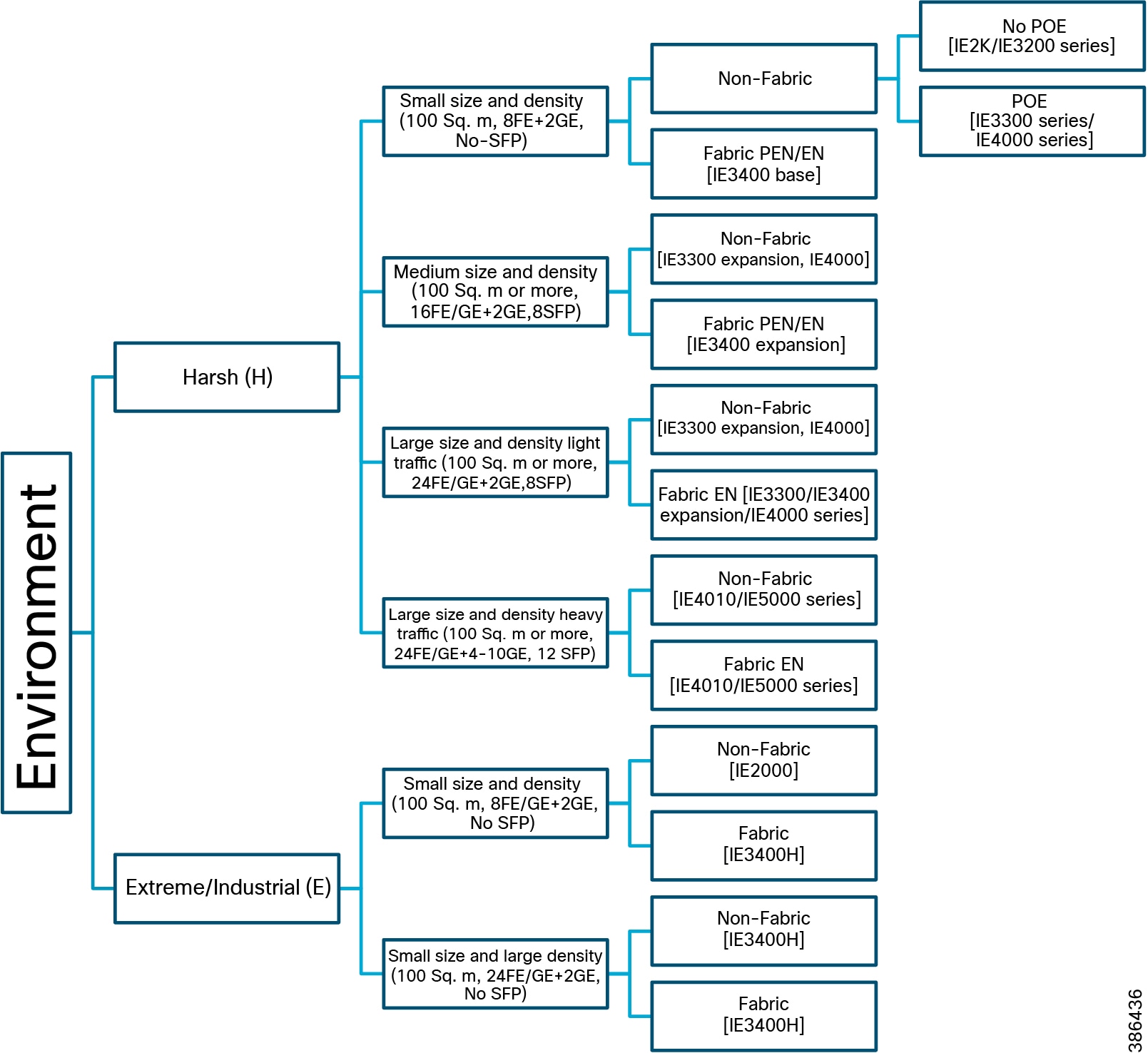
Figure 45 Device Selection Decision Tree for Automated Cranes in Ports
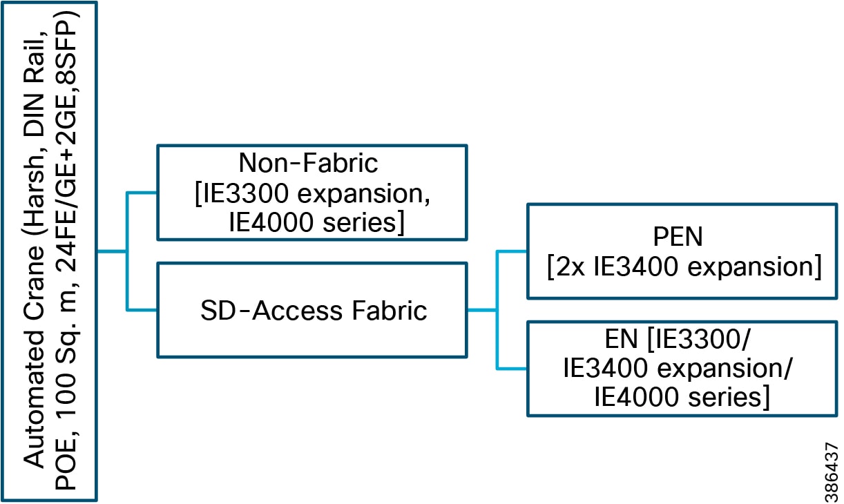
Refer to Table 9 for dimensioning of the WLC. Due to their scalability and feature support for large centralized (local-mode) designs, the recommended platform for WLC is the Cisco WLC 5520.
Extended Enterprise Use Case BOM Guidance
Each deployment has its own unique characteristics. For example, extending the enterprise network to the campus parking lot of an organization location can be quite different from another location of the same organization due to its size, shape, environment, available infrastructure, and so on. However, a number of basic building block models are described in Table 21 and Table 22, envisaging that any extended enterprise deployment can be broken into a set of smaller blocks each mapping to a one of the these identified models. Once a block is mapped to a model in Table 21 and Table 22, the BOM is defined.
Campus/Stadium Parking Lot BOM Guidance
Use cases: Enterprises/stadiums want to extend their IT networks to cover their campus parking lots. Various prominent use cases for extended enterprise IT connectivity include deploying video surveillance cameras for safety and security, providing seamless wireless connectivity to employees and guests, providing VOIP-based emergency calling points, and connecting third-party systems for safety alarms.
Challenges: The environmental conditions for the campus/stadium parking lot depend on the organization's geographical location and surroundings. The management for the parking lot network will be an extension to the organization’s management, which could be non-fabric or SD-Access fabric. Another consideration is power supply availability across the parking lot, which could be based on solar power, A/C power, or no-power (PoE is needed to power on the devices).
Similar to an enterprise network, the extended enterprise campus parking lot network needs to support security features such as AAA features and segmentation and ease of management features such as PNP onboarding.
Solution: An example BOM derivation for a campus/stadium parking lot is shown in Table 23. The steps are:
1.![]() Total parking area is divided into multiple blocks, each fitting into one of the categories listed in Table 21/Figure 44. For example, an area block is considered as “Small size and small density” if the block area is less than 100 Sq. m, requires up to 8 copper FE access ports for connecting end devices, and requires maximum 2 GE for uplink. The parking lot in this example is considered to have 50 Small size and small density blocks, 25 Medium size and density blocks, and so on. Refer to Table 23 for details.
Total parking area is divided into multiple blocks, each fitting into one of the categories listed in Table 21/Figure 44. For example, an area block is considered as “Small size and small density” if the block area is less than 100 Sq. m, requires up to 8 copper FE access ports for connecting end devices, and requires maximum 2 GE for uplink. The parking lot in this example is considered to have 50 Small size and small density blocks, 25 Medium size and density blocks, and so on. Refer to Table 23 for details.
2.![]() Different wired end devices deployed in the parking lot are cameras and VOIP phones. Two scenarios are considered: local power available and PoE/UPoE power required.
Different wired end devices deployed in the parking lot are cameras and VOIP phones. Two scenarios are considered: local power available and PoE/UPoE power required.
3.![]() The parking lot area is considered as Harsh outdoor.
The parking lot area is considered as Harsh outdoor.
4.![]() For illustration a couple of enterprise deployment scenarios are considered, namely Non-Fabric and SD-Access fabric - PEN.
For illustration a couple of enterprise deployment scenarios are considered, namely Non-Fabric and SD-Access fabric - PEN.
5.![]() The values in the BOM columns are chosen based on Table 21/Figure 44.
The values in the BOM columns are chosen based on Table 21/Figure 44.
Automated Crane BOM Guidance for Ports
Use cases: Ports are in spree of digitizing their operations and equipment. Advanced use cases such as automated guided vehicles (AGV) and automated cranes are some of the prominent use cases. These digitization/automation drives improve productivity and safety while reducing errors. This is very useful especially in case of taller STS cranes where the abilities of human eyes become a limitation due to the physical distance between the cabin and the target. Prominent end equipment for the automated crane operations include automation systems mounted on the cranes and multiple cameras.
Challenges: The environmental conditions for these cranes and onboard mounting locations are often harsh, needing ruggedized equipment. The management of the on-board devices, will be an part of a larger ecosystem, which could be non-fabric or SD-Access fabric. One other consideration is availability of power supply for various mounted equipment such as automation systems and cameras. Often PoE is a preferred power option. Overall security of the devices and operations such as AAA and segmentation are of high importance. Ease of management such as PNP onboarding, single-pane-of-glass are crucial.
Solution: An example BOM derivation for an automated crane, based on Table 22/Figure 45, is shown in Table 24. The steps are:
1.![]() The IP connectivity is extended to the automated crane by mounting hardened IE switches on the crane. Because there are a large number of endpoints on the crane to connect to the IE switch, many of them within 100 meters, up to 24 FE/GE ports are needed along with up to 8 SFP ports. Up to 2 GE ports are needed for uplink.
The IP connectivity is extended to the automated crane by mounting hardened IE switches on the crane. Because there are a large number of endpoints on the crane to connect to the IE switch, many of them within 100 meters, up to 24 FE/GE ports are needed along with up to 8 SFP ports. Up to 2 GE ports are needed for uplink.
2.![]() Wired end devices deployed in the automated crane include automated systems and cameras.
Wired end devices deployed in the automated crane include automated systems and cameras.
3.![]() The automated crane and mount points area considered to be of Harsh outdoor environment.
The automated crane and mount points area considered to be of Harsh outdoor environment.
4.![]() For illustration enterprise management such as Non-Fabric, SD-Access fabric-EN, SD-Access fabric-PEN are considered.
For illustration enterprise management such as Non-Fabric, SD-Access fabric-EN, SD-Access fabric-PEN are considered.
5.![]() The values in the BOM columns are chosen based on Table 22/Figure 45.
The values in the BOM columns are chosen based on Table 22/Figure 45.
Extended Enterprise Single Pane of Glass Management
This section is a brief summary of unified management of enterprise and Extended Enterprise networks by Cisco DNA Center, which groups the supported features into Design, Policy, Provision, Assurance, and Platform.
Figure 46 shows different feature groups of the Cisco DNA Center and workflow in performing network operations:
Figure 46 Cisco DNA Center Workflow
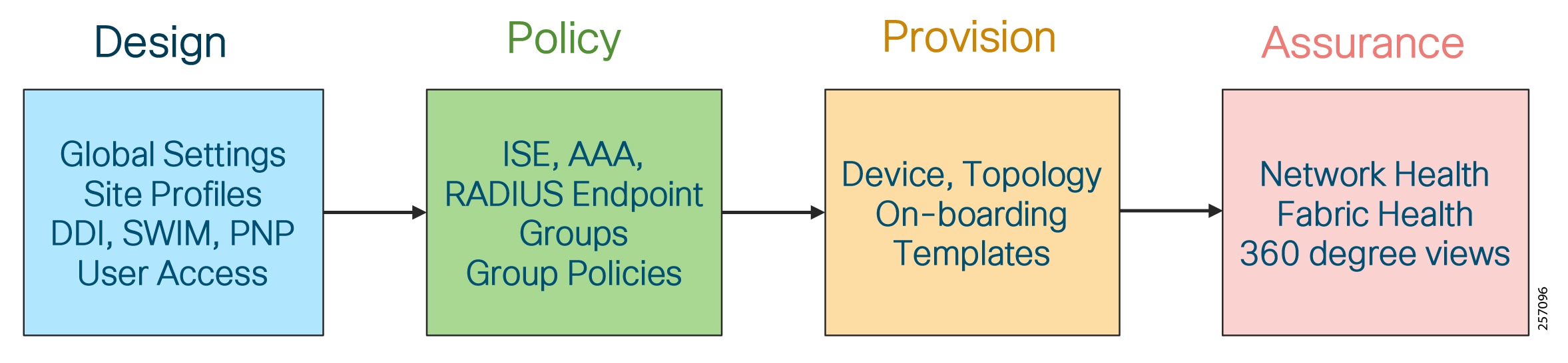
Design Support
Configures device global settings, network site profiles for physical device inventory, DNS, DHCP, IP addressing, software image management, PnP, and user access.
–![]() Zero touch provisioning: Connect a brand new device to the network having reachability to the Cisco DNA Center. The device is then onboarded.
Zero touch provisioning: Connect a brand new device to the network having reachability to the Cisco DNA Center. The device is then onboarded.
–![]() User can define an on-boarding template to be executed as part of the on-boarding workflow.
User can define an on-boarding template to be executed as part of the on-boarding workflow.
–![]() User-defined workflow (site assignment, software image upgrade, and onboarding template) is executed during on-boarding.
User-defined workflow (site assignment, software image upgrade, and onboarding template) is executed during on-boarding.
–![]() Onboarded device is added to inventory.
Onboarded device is added to inventory.
–![]() Discover a range of devices (Cisco switch, router, and AP) and their topology.
Discover a range of devices (Cisco switch, router, and AP) and their topology.
–![]() Discovered devices are added to inventory.
Discovered devices are added to inventory.
–![]() All devices in the inventory are polled for links, hosts, and interfaces at regular intervals and their status is maintained. The poll interval can vary from 25 minutes to 24 hours. To prevent stale devices, only the devices found active within less than a day are displayed. On an average, polling 500 devices takes approximately 20 minutes.
All devices in the inventory are polled for links, hosts, and interfaces at regular intervals and their status is maintained. The poll interval can vary from 25 minutes to 24 hours. To prevent stale devices, only the devices found active within less than a day are displayed. On an average, polling 500 devices takes approximately 20 minutes.
–![]() From all active devices in the inventory, several statistics are collected for reporting and assurance.
From all active devices in the inventory, several statistics are collected for reporting and assurance.
■![]() Provisioning Devices in Inventory:
Provisioning Devices in Inventory:
–![]() Day N automation template can be executed on any device.
Day N automation template can be executed on any device.
–![]() Network abstraction and visualization with hierarchical drill-down views.
Network abstraction and visualization with hierarchical drill-down views.
■![]() Manage Software Image (SWIM): Cisco DNA Center maintains image repository and maintenance updates (SMUs) for all devices in the network. Cisco DNA Center performs integrity check for the software images stored in the repository. The operator can designate a specific version of software and SMU as a golden image for each device type and role. Cisco DNA Center auto-checks the software version of devices and raises an alert for the device that has an outdated version (not matching golden image). The operator can push software to the desired list of devices. The Cisco DNA Center performs upgrade readiness check before pushing software to the device and checks system state after upgradation.
Manage Software Image (SWIM): Cisco DNA Center maintains image repository and maintenance updates (SMUs) for all devices in the network. Cisco DNA Center performs integrity check for the software images stored in the repository. The operator can designate a specific version of software and SMU as a golden image for each device type and role. Cisco DNA Center auto-checks the software version of devices and raises an alert for the device that has an outdated version (not matching golden image). The operator can push software to the desired list of devices. The Cisco DNA Center performs upgrade readiness check before pushing software to the device and checks system state after upgradation.
Policy Support
■![]() Defines business intent for provisioning into the network, policy contract definition for groups.
Defines business intent for provisioning into the network, policy contract definition for groups.
■![]() Policy-driven security—Group-based access policy, policy to users and applications not just device. Cisco ISE is responsible for device profiling, identity services, and policy services, dynamically exchanging information with the Cisco DNA Center.
Policy-driven security—Group-based access policy, policy to users and applications not just device. Cisco ISE is responsible for device profiling, identity services, and policy services, dynamically exchanging information with the Cisco DNA Center.
■![]() Policy-driven QoS defined at Cisco DNA Center is auto-configured in the entire network hierarchy.
Policy-driven QoS defined at Cisco DNA Center is auto-configured in the entire network hierarchy.
Provision Support
■![]() Provision device as per user defined role—Provision Cisco Unified Wireless Network wireless and external connectivity. Role-based provisioning in case of fabric site such as creating fabric domains, control plane nodes, border nodes, edge nodes, and fabric wireless.
Provision device as per user defined role—Provision Cisco Unified Wireless Network wireless and external connectivity. Role-based provisioning in case of fabric site such as creating fabric domains, control plane nodes, border nodes, edge nodes, and fabric wireless.
Assurance Support
In the Extended Enterprise design, we have different types of endpoints—laptops, cameras, phones and different types of users—employee, contractor accessing the network using either wired/wireless means. In such a diverse environment, it is very important to troubleshoot the problems and come to a quick resolution. When an endpoint is unable to connect successfully to the network, many reasons for having a failure could exist such as issues related to authentication service, end point OS problems, and physical network issues. The Cisco DNA Center helps operation teams quickly isolate the root cause of the problem. To obtain more information about Cisco DNA Center assurance, please visit the Cisco DNA Center Solutions web page at the following URL:
■![]() https://dnac.cisco.com/dnac-solutions/dna-assurance
https://dnac.cisco.com/dnac-solutions/dna-assurance
Some of the key assurance benefits are:
■![]() Enables proactive monitoring and insights to confirm user experience meets configured intent, using network, client, and application health dashboards, issue management, and sensor-driven testing.
Enables proactive monitoring and insights to confirm user experience meets configured intent, using network, client, and application health dashboards, issue management, and sensor-driven testing.
■![]() Basic Assurance—Assurance then assesses the network and uses context to turn data into intelligence, making sure that changes in the network device policies achieve your intent.
Basic Assurance—Assurance then assesses the network and uses context to turn data into intelligence, making sure that changes in the network device policies achieve your intent.
■![]() Advanced Assurance—A health score on the Cisco DNA Center dashboard can help detect performance issues and identify the most likely cause. Several 360-degree view health dashboards are presented in the Cisco DNA Center, namely System-360, Network-360, Device-360, and Client-360.
Advanced Assurance—A health score on the Cisco DNA Center dashboard can help detect performance issues and identify the most likely cause. Several 360-degree view health dashboards are presented in the Cisco DNA Center, namely System-360, Network-360, Device-360, and Client-360.
■![]() Single Pane of Glass—To manage and automate with intuitive workflows and reusable templates.
Single Pane of Glass—To manage and automate with intuitive workflows and reusable templates.
■![]() Unified Enterprise Network—Covering heterogeneous wired and wireless networks, spanning geographies across buildings and cities.
Unified Enterprise Network—Covering heterogeneous wired and wireless networks, spanning geographies across buildings and cities.
Platform Support
■![]() Allows programmatic access to the network and system integration with third-party systems using APIs, using feature set bundles, configurations, a runtime dashboard, and a developer toolkit.
Allows programmatic access to the network and system integration with third-party systems using APIs, using feature set bundles, configurations, a runtime dashboard, and a developer toolkit.
■![]() Platform-related features such as intent API to programmatically access network, integrate with third party systems, and support multi-vendor devices.
Platform-related features such as intent API to programmatically access network, integrate with third party systems, and support multi-vendor devices.
■![]() Runtime dashboard showing North Bound Interface and API, events summary.
Runtime dashboard showing North Bound Interface and API, events summary.
Summary
In summary, the Cisco Extended Enterprise solution enables enterprises to seamlessly extend existing enterprise networks to non-carpeted spaces such as campus parking lots, warehouses, distribution centers, ports, and airports. The solution outlines the steps for both IT and operations teams to accomplish business goals by digitizing the operations in the ruggedized spaces.
Appendix A—Related Documentation
■![]() Cisco Internet of Things Overview:
Cisco Internet of Things Overview:
–![]() https://www.cisco.com/c/en/us/solutions/internet-of-things/overview.html
https://www.cisco.com/c/en/us/solutions/internet-of-things/overview.html
■![]() Cisco Industrial Ethernet switching product page:
Cisco Industrial Ethernet switching product page:
–![]() https://www.cisco.com/c/en/us/products/switches/industrial-ethernet-switches/index.html
https://www.cisco.com/c/en/us/products/switches/industrial-ethernet-switches/index.html
■![]() Cisco Outdoor and Industrial Wireless product page:
Cisco Outdoor and Industrial Wireless product page:
–![]() https://www.cisco.com/c/en/us/products/wireless/outdoor-wireless/index.html
https://www.cisco.com/c/en/us/products/wireless/outdoor-wireless/index.html
■![]() Cisco Extended Enterprise - Getting Started:
Cisco Extended Enterprise - Getting Started:
–![]() https://www.cisco.com/c/en/us/solutions/internet-of-things/extended-enterprise.html
https://www.cisco.com/c/en/us/solutions/internet-of-things/extended-enterprise.html
■![]() Cisco Intent-Based Networking Overview:
Cisco Intent-Based Networking Overview:
–![]() https://www.cisco.com/c/en/us/solutions/intent-based-networking.html
https://www.cisco.com/c/en/us/solutions/intent-based-networking.html
■![]() White paper: Intent-Based Networking and Extending the Enterprise:
White paper: Intent-Based Networking and Extending the Enterprise:
–![]() https://www.cisco.com/c/dam/en/us/solutions/collateral/internet-of-things/nb-09-intent-based-iot-wp-cte-en.pdf
https://www.cisco.com/c/dam/en/us/solutions/collateral/internet-of-things/nb-09-intent-based-iot-wp-cte-en.pdf
■![]() Design Zone for Cisco Enterprise Networks:
Design Zone for Cisco Enterprise Networks:
–![]() https://www.cisco.com/c/en/us/solutions/design-zone/networking-design-guides.html
https://www.cisco.com/c/en/us/solutions/design-zone/networking-design-guides.html
■![]() Campus LAN and Wireless LAN Design Guide:
Campus LAN and Wireless LAN Design Guide:
–![]() https://www.cisco.com/c/dam/en/us/td/docs/solutions/CVD/Campus/CVD-Campus-LAN-WLAN-Design-Guide-2018JAN.pdf
https://www.cisco.com/c/dam/en/us/td/docs/solutions/CVD/Campus/CVD-Campus-LAN-WLAN-Design-Guide-2018JAN.pdf
■![]() Refer to the CVD Software-Defined Access Design Guide:
Refer to the CVD Software-Defined Access Design Guide:
–![]() https://cvddocs.com/fw/250-prime
https://cvddocs.com/fw/250-prime
■![]() Refer to the CVD Software-Defined Access Deployment Guide:
Refer to the CVD Software-Defined Access Deployment Guide:
–![]() https://cvddocs.com/fw/251-prime
https://cvddocs.com/fw/251-prime
■![]() Software-Defined Access Segmentation Design Guide:
Software-Defined Access Segmentation Design Guide:
–![]() https://www.cisco.com/c/dam/en/us/td/docs/solutions/CVD/Campus/CVD-Software-Defined-Access-Segmentation-Design-Guide-2018MAY.pdf
https://www.cisco.com/c/dam/en/us/td/docs/solutions/CVD/Campus/CVD-Software-Defined-Access-Segmentation-Design-Guide-2018MAY.pdf
Appendix B—Glossary
This table lists the acronyms and initialisms used in this document.
AES-Counter Mode CBC-MAC Protocol (AES - Advanced Encryption Standard) |
|
representational state transfer application program interface |
|
 Feedback