Configuration Using the Admin UI

The initial setup and configuration wizard is described in the Cisco Threat Grid Appliance Getting Started Guide. New Threat Grid Appliances may require the administrator to complete additional configuration, and Admin UI settings may require updates over time. This chapter provides information about using the Admin UI to make configuration changes to your appliance.

About the Admin UI

The Admin UI is the Threat Grid Appliance administrator's main configuration interface. It is a Web portal that can be used once an IP address has been configured on the Threat Grid Appliance Admin interface.


Note

The initial setup and configuration wizard is described in the Cisco Threat Grid Appliance Getting Started Guide.


Figure 1. Configuration

The Configuration menu in the Admin UI is used to configure and manage various Threat Grid Appliance configuration settings, including:

Section

Description

Authentication

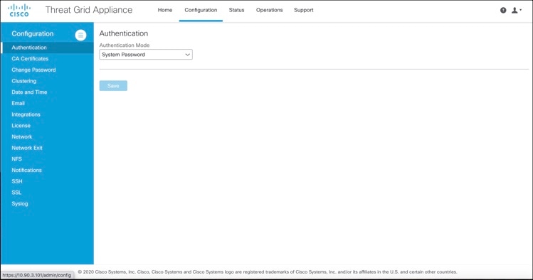
Describes how to configure LDAP and RADIUS authentication for logging into the Threat Grid Appliance Admin UI.

CA Certificates

Describes how to add CA certificate for outbound SSL connections for the appliance to trust the Cisco AMP for Endpoints Private Cloud.

Change Password

Describes how to change your Admin UI password.

Clustering

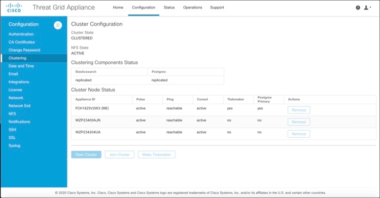
Describes features, limitations, and requirements of clustering Threat Grid Appliances; network and NFS storage requirements; how to build a cluster, join appliances to the cluster, remove cluster nodes, and designate a tie-breaker node; failure tolerances and failure recovery; API and operational usage and characteristics for clusters, and sample deletion.

Date and Time

Describes how to add Network Time Protocol (NTP) server to configure date and time.

Email

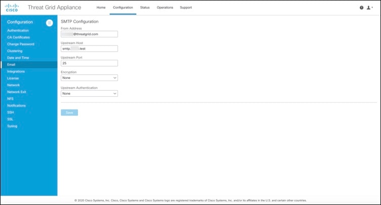
Describes how to configure your email settings (SMTP) for system notifications.

Integrations

Describes how to configure third-party detection and enrichment services (OpenDNS, TitaniumCloud, VirusTotal); enable or disable ClamAV automatic updates.

License

Describes how to upload your Threat Grid Appliance license or retrieve it from the server.

Network

Describes how to adjust the IP assignment from DHCP to your permanent static IP addresses, and how to configure DNS.

Network Exit

Describes how to configure the network exit options that are available in the Threat Grid portal when submitting samples for analysis.

NFS

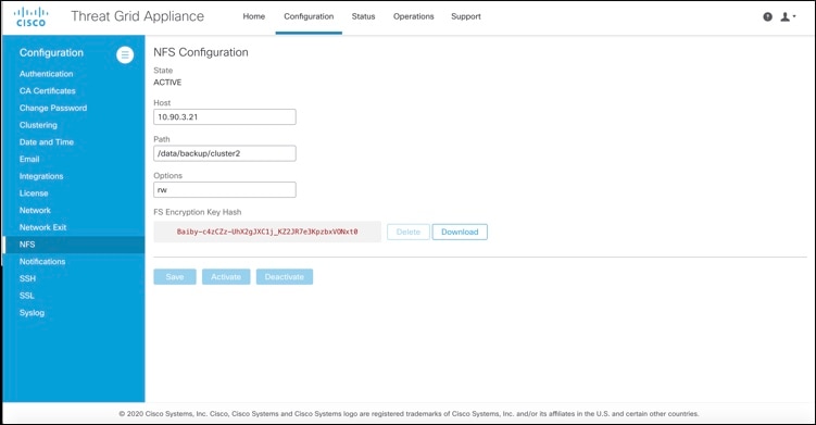
Describes appliance backup, including NFS requirements, backup storage requirements, backup expectations, and configuring the strict retention period limits; how to perform a backup.

Notifications

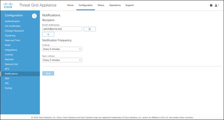
Describes how to manage notification recipients.

SSH

Describes how to set up SSH keys to provide access to the TGSH Dialog via SSH.

SSL

Describes how to configure SSL certificates to support Threat Grid Appliance connections with Email Security Appliance (ESA), Web Security Appliance (WSA), AMP for Endpoints Private Cloud, and other integrations; replacing SSL certificates.

Syslog

Describes how to configure a system log server to receive syslog messages and notifications.


Note

  • Configuration updates in the Admin UI should be completed in one session to reduce the chance of an interruption to the IP address during configuration.

  • The Admin UI does not validate the gateway entries. If you enter the wrong gateway and save it, the Admin UI will not be accessible. You will need to use the console to fix the networking configuration if that was done on the Admin interface. If Admin is still valid, you can fix it in the Admin UI and reboot.

  • Threat Grid Appliances (v2.7 or later) use the serial number as the hostname to improve interoperability with some NFS v4 servers.


Important

The Admin UI uses HTTPS and you must enter this in the browser address bar; pointing to only the Admin IP is not sufficient. Enter the following address in your browser:

https://adminIP/

OR

https://adminHostname/


Applying Configuration Changes

Any time changes are made to configuration settings, a light orange alert message appears in a banner in the upper portion of the Configuration page.

Figure 2. Reconfigure Required Alert Message

Changes to the Admin UI configuration settings must be saved, and several also include a step to activate the change. However, you must also finalize the changes with a reconfiguration in a separate step. Configuration changes do not take effect until reconfiguration is completed.


Note

Reconfiguration may affect other users logged in to Threat Grid portal and the Admin UI.


Procedure


Step 1

Click Reconfigure on the alert message to launch the reconfiguration process.

Step 2

On the Activate Configuration page, click Reconfigure to run the reconfiguration job.

Step 3

On the confirmation dialog, click Reconfigure to start the reconfiguration job.

Configuration is activated, and messages on its progress are displayed in the jobs window. Details are kept in the Jobs page if you need to review error messages or other information.

When completed, a confirmation message is displayed indicating the reconfiguration was successful.

Step 4

Click Continue.


Authentication

The Threat Grid Appliance supports LDAP authentication and authorization for logging into the Admin UI and the TGSH Dialog. It also supports RADIUS authentication, which allows for single sign-on to the Admin UI in v2.10 and later.

LDAP Authentication

The Threat Grid Appliance supports LDAP authentication and authorization for Admin UI and TGSH Dialog login. You can authenticate multiple appliance administrators with different credentials that are managed on the domain controller or the LDAP server. Authentication modes include: System Password Only, System Password or LDAP, and LDAP Only.

There are three LDAP Protocol options: LDAP, LDAPS, and LDAP with STARTLS.

The following considerations should be observed:

  • The dual authentication mode (System Password or LDAP) is required to avoid accidentally locking yourself out of the Threat Grid Appliance when setting up LDAP.

    Choosing LDAP Only is not allowed initially; you must first go through dual mode to make sure it works. You must log out of the Admin UI after the initial configuration, and then log back in using LDAP credentials to toggle to LDAP Only.

  • You can only log into the TGSH Dialog using LDAP if you are configured for LDAP Only authentication. If authentication mode is set to System Password or LDAP, the TGSH Dialog login only allows the System login.

  • If the Threat Grid Appliance is configured for LDAP authentication only (LDAP Only), you can reset the password in recovery mode to reconfigure the authentication mode to also allow login with a system password.

  • Make sure that the authentication filter is set up to restrict membership.

  • The TGSH Dialog and the Admin UI require LDAP credentials only in LDAP Only mode/ if LDAP only is configured, the TGSH Dialog only prompts for the LDAP user/password; not the system password.

  • If authentication is configured for System Password or LDAP, the TGSH Dialog prompts for for only the system password; not both.

  • To troubleshoot LDAP issues, disable it by resetting the password in Recovery Mode.

  • To access the TGSH Dialog via SSH, a system password or a configured SSH key is required in addition to LDAP credentials when in LDAP Only mode.

  • LDAP is outbound from the Clean interface.

Perform the following steps to configure LDAP authentication in the Admin UI.

Procedure


Step 1

Click the Configuration and choose Authentication.

Step 2

From the Authentication Mode drop-down, choose LDAP or System Password to open the LDAP configuration page.

Note 

The first time you configure LDAP authentication, you must choose LDAP or System Password, log out of the Admin UI, and then log back in using your LDAP credentials. You can then change the setting to LDAP.

Figure 3. LDAP Authentication Configuration Page
Step 3

Complete the fields on the page as appropriate:

  • Hostname - The host name to connect to via LDAP.

  • Port - The port number to connect to via LDAP (default 389).

  • Authentication Mode - The authentication mode to be used upon login.

  • LDAP Protocol - The LDAP protocol in use.

  • Bind Password - The password to use for binding via LDAP.

  • Bind DN -The Distinguished Name to bind to via LDAP; for example: cn=admin,dc=foo,dc=com.

  • Base - The base to bind to via LDAP; for example: ou=users,dc=foo,dc=com (LDAP only).

  • Authentication Filter - The filter to be applied for authentication upon login; for example: (&(cn=%LOGIN%) (memberOf=cn=admingroup, ou=groups,dc=foo,dc=com)).

Step 4

Click Save.

When users log in to the Admin UI or TGSH Dialog, they will now be prompted for their LDAP authentication.


RADIUS Authentication

Threat Grid Appliance (v2.10 and later) supports RADIUS authentication, which uses Cisco Identity Services Engine with DTLS enabled. If RADIUS authentication is enabled, users can log in to the main Threat Grid application UI with the appropriate single sign-on password.

Perform the following steps in the Admin UI to configure RADIUS authentication:

Procedure


Step 1

Click the Configuration tab and choose Authentication.

Step 2

From the Authentication Mode drop-down, choose RADIUS or System Password to open the RADIUS configuration page.

Note 

The first time you configure RADIUS authentication, you must choose RADIUS or System Password, log out of the Admin UI, and then log back in using your RADIUS credentials. You can then change the setting to RADIUS.

Figure 4. RADIUS Authentication Configuration Page
Step 3

Complete the fields on the page as appropriate:

  • Hostname - The host name to connect to via RADIUS.

  • Port - The DTLS port number to connect to via RADIUS (default 2083). Unlike conventional RADIUS, DTLS uses a single port for both authentication and accounting. Only DTLS-based RADIUS authentication is supported.

  • Initial Face Admin - The RADIUS user to whom the initial/default administration user in the primary Threat Grid UI shall be mapped. This account should be the party responsible for creating other user accounts in Threat Grid and configuring their permissions.

  • CA Certificate - A PEM-format CA certificate to be used to authenticate the RADIUS server used for authentication. Will change to <VALID> when successfully saved. Clear this to empty the field.

  • Client Certificate - A PEM-format client certificate to be used to authenticate this host to the RADIUS server used for authentication. This value will change to <VALID> when successfully saved; you can clear it to empty the field.

  • Client Private Key - A PEM-format key to be used to authenticate this host to the RADIUS server used for authentication. The value must correspond with the client certificate given above. The value will change to <VALID> when successfully saved; you can clear it to empty the field. Private keys in PEM-encoded PKCS#8 format are supported by the new Admin UI.

Step 4

Click Save.


CA Certificates

The CA Certificates page in the Admin UI is used to manage the Certificate Authority (CA) certificate trust store for outbound SSL connections so that the Threat Grid Appliance can trust the Cisco AMP for Endpoints Private Cloud to notify it about analyzed samples that are considered malicious.

Procedure


Step 1

Click the Configuration tab and choose CA Certificates to open the CA Certificates page.

Figure 5. CA Certificates Page
Step 2

Create a .pem file that contains the outbound SSL connections (CA certificates) for the AMP for Endpoints Private Cloud, copy the contents, and paste it into the Certificate field.

Step 3

Click Add Certificate and confirm. Changing a CA certificate does ot require reconfiguration.


Change Password

Your appliance password is used to authenticate to the Threat Grid Appliance Admin UI as well as the appliance console. You can change your password from the Admin UI using the Change Password page.


Note

It may not be possible to paste complex passwords or passwords with non-keyboard characters into the console so be careful when you change your password.


Procedure


Step 1

Click the Configuration tab and choose Change Password.

Figure 6. Change Password
Step 2

Enter your Current Password, and then enter the New Password and Confirm Password.

Step 3

Click Change Password and confirm the change. Changing a password does not require reconfiguration.


Clustering

The ability to cluster multiple Threat Grid Appliances is available in v2.4.2 and later. Each Threat Grid Appliance in a cluster saves data in the shared file system, and has the same data as the other nodes in the cluster.

The main goal of clustering is to increase the capacity of a single system by joining several Threat Grid Appliances together into a cluster (consisting of 2 to 7 nodes). Clustering also helps support recovery from failure of one or more appliances in the cluster, depending on the cluster size.

For more information about clustering, see the Threat Grid Appliance Clustering FAQ.


Important

If you have questions about installing or reconfiguring clusters, contact Cisco Support for assistance to avoid possible destruction of data.


Features

Clustering Threat Grid Appliances offers the following features:

  • Shared Data - Every Threat Grid Appliance in a cluster can be used as if it a standalone; each one is accessing and presenting the same data.

  • Sample Submissions Processing - Submitted samples are processed on any one of the cluster members, with any other member able to see the analysis results.

  • Rate Limits - The submission rate limits of each member are added up to become the cluster's limit.

  • Cluster Size - The preferred cluster sizes are 3, 5, or 7 members; 2-, 4- and 6-node clusters are supported, but with availability characteristics similar to a degraded cluster (a cluster in which one or more nodes are not operational) of the next size up.

  • Tiebreaker - When a cluster is configured to contain an even number of nodes, the one designated as the tiebreaker gets a second vote in the event of an election to decide which node has the primary database.

    Each node in a cluster contains a database, but only the database on the primary node is actually used; the others just have to be able to take over if and when the primary node goes down. Having a tiebreaker can prevent the cluster from being down when exactly half the nodes have failed, but only when the tiebreaker is not among the failed nodes.

    Odd-numbered clusters won't have a tied vote. In an odd-numbered cluster, the tiebreaker role only becomes relevant if a node (not the tiebreaker) is dropped from the cluster; it then becomes even-numbered.


    Note

    This feature is fully tested only for clusters with two nodes.


Limitations

Clustering Threat Grid Appliances has the following limitations:

  • When building a cluster of existing standalone Threat Grid Appliances, only the first node (the initial node) can retain its data. The other nodes must be manually reset because merging existing data into a cluster is not allowed.

    Remove existing data with the destroy-data command, as documented in Reset Appliance as Backup Restore Target


    Important

    Do not use the Wipe Appliance feature as it will render the appliance inoperable until it's returned to Cisco for reimaging.


  • Adding or removing nodes can result in brief outages, depending on cluster size and the role of the member nodes.

  • Clustering on the M3 server is not supported. Contact Threat Grid Support if you have any questions.

Requirements


Important

Clustering in Airgapped Deployments Strongly Discouraged - Due to the increased complexity of debugging, appliance clustering is strongly discouraged in airgapped deployments or other scenarios where a customer is unable or unwilling to provide L3 support access to debug.


The following requirements must be met when clustering Threat Grid Appliances:

  • Version - All Threat Grid Appliances must be running the same version to set up a cluster in a supported configuration; it should always be the latest available version.

  • Clust Interface - Each Threat Grid Appliance requires a direct interconnect to the other Threat Grid Appliances in the cluster; a SFP+ must be installed in the Clust interface slot on each Threat Grid Appliance in the cluster (not relevant in a standalone configuration).

    Direct interconnect means that all Threat Grid Appliances must be on the same layer-two network segment, with no routing required to reach other nodes and no significant latency or jitter. Network topologies where the nodes are not on a single physical network segment are not supported.

  • Data - A Threat Grid Appliance can only be joined to a cluster when it does not contain data (only the initial node can contain data). Moving an existing Threat Grid Appliance into a data-free state requires the use of the database reset process (available in v2.2.4 or later).


    Important

    Do not use the destructive Wipe Appliance process, which removes all data and renders the application inoperable until it's returned to Cisco for reimaging.


  • SSL Certificates - If you are installing SSL certificates signed by a custom CA on one cluster node, then the certificates for all of the other nodes should be signed by the same CA.

Networking and NFS Storage

Clustering Threat Grid Appliances requires the following networking and NFS storage considerations:

  • Threat Grid Appliance clusters require a NFS store to be enabled and configured. It must be available via the Admin interface and accessible from all cluster nodes.

  • Each cluster must be backed by a single NFS store with a single key. While that NFS store may be initialized with data from a pre-existing Threat Grid Appliance, it must not be accessed by any system that is not a member of the cluster while the cluster is in operation.

  • The NFS store is a single point of failure, and the use of redundant, highly reliable equipment for that role is essential.

  • The NFS store used for clustering must keep its latency consistently low.

Figure 7. Clustering Network Diagram

Building a Threat Grid Appliance Cluster

Building a Threat Grid Appliance cluster in a supported manner requires that all members be on the same version, which should always be the latest available version. This may mean that all of the members have to be built standalone first to get fully updated.

If the Threat Grid Appliance has been in use as a standalone appliance prior to clustering, only the data of the first member can be preserved. The others need to be reset as part of the build.

Start a new cluster with an initial node, and then join other Threat Grid Appliances to it. There are two distinct paths that are available for building a new cluster:

Clust Interface Setup

Each appliance in the cluster requires an additional SFP+ for the Clust interface. Install a SFP+ module in the fourth (non-Admin) SFP port. On the M5, this is the second SPF interface from the left (see the Cisco Threat Grid M5 Hardware Installation Guide for more information).

Figure 8. Clust Interface Setup for Cisco UCS M4 C220

Cluster Configuration

Clusters are configured and managed in the Admin UI on the Cluster Configuration page (Configuration > Clustering). This section describes the fields on this page to gain an understanding of an active and healthy cluster (the screenshot shows a cluster with three nodes).

Figure 9. Cluster Configuration for Active Cluster
Cluster Prerequisites
  • The appliance must be fully set up and configured.

  • The NFS State must be Active.

Cluster State
  • Unconfigured - Not yet configured as explicitly part of a cluster or as a standalone Threat Grid Appliance; you make this choice in the initial setup wizard if the prerequisites for clustering have been met.

  • Pending_NFS_Enable - Cluster is pending NFS enablement.

  • Pending_NFS_Key - Cluster is pending NFS key.

  • Standalone - Appliance is configured as a standalone node; cannot be configured as part of a cluster without a reset.

  • Clustered - Is clustered with one or more other Threat Grid Appliances.

  • Unknown - Status cannot be determined.

Clustering Components Status
  • Elasticsearch- The service used for queries that require search functionality.

  • PostgreSQL - The service used for queries that require up-to-date, definitive data (such as account lookups).

Both services are described with one of the following status values:

  • Replicated - Everything is working properly. Additionally, everything required to take over on failure is also in place. The appliance is able to tolerate failure and continue working. Being in a replicated state does not mean that a failure will have zero downtime. Rather, a failure should entail zero data loss and constrained downtime (less than a minute in normal circumstances, with the exception of any active analysis on the specific cluster node that fails).

    Maintenance operations that bring down nodes should only be performed when the cluster is in the replicated state.

    For a fully replicated cluster, recovery should be automatic and require less than a minute to complete in any normal scenario.

  • Available - Everything is working properly and the referenced service is available for use (that is, it can service API and user requests), but it is not replicated.

  • Unavailable - The service is known to be non-functional.

For more information, see the Threat Grid Appliance Clustering FAQ on Cisco.com.

Cluster Nodes Status
  • Pulse - Indicates whether the node is actively connected to and using the NFS store (not during initial setup, but while running services).

  • Ping - Describes whether the cluster node can be seen over the Clust interface.

  • Consul - Indicates whether the node is participating in the consensus store. This requires both a network connection over Clust and a compatible encryption key.

  • Tiebreaker - Designates the node as the tiebreaker, which will cast the deciding vote in an election to decide the cluster's primary node. See Designate Tiebreaker Node.

  • Postgres Primary - Indicates whether the node is the PostgreSQL primary node.

Start Building Cluster from Existing Standalone Appliance

When you start building a cluster of Threat Grid Appliances, you must start the cluster with the first node being either an existing standalone Threat Grid Appliance or a new appliance. This section describes how to build a cluster from an existing standalone Threat Grid Appliance, which allows you to preserve existing data from one appliance and use it to start a new cluster.


Note

  • An existing backup must be available on NFS from which the cluster is started.

  • All other nodes to be joined to the cluster must have data removed before joining; the data from additional nodes cannot be merged into the cluster.

  • In releases prior to v2.4.3, standalone Threat Grid Appliances with data backed up to NFS no longer require a database reset and restore-from-backup to become the initial node of a new cluster. If you have a Threat Grid Appliance with an earlier version, we suggest that you upgrade to v2.4.3 or later and then perform a reset operation prior to initializing a new cluster.


Perform the following steps to start building the first node in a cluster from an existing standalone appliance:

Procedure

Step 1

Fully update the Threat Grid Appliance to the latest version. Depending on which version is currently running, this may require more than one update cycle to reach the latest version.

Step 2

If not already completed, configure NFS for backup of the appliance:

Note 

This step describes the default Linux NFS server implementation; it may be different for your server setup.

  1. Click the Configuration tab and choose NFS to open the NFS Configuration page.

    Figure 10. NFS Configuration
  2. Complete the following fields:

    • Host - The NFSv4 host server. We recommend using the IP address.

    • Path - The absolute path to the location on the NFS host server where files will be stored. This does not include the Key ID suffix, which will be added automatically.

    • Options - NFS mount options to be used, if this server requires any deviations from standard Linux defaults for NFSv4.

  3. Click Save.

    The page refreshes and the Generate Key button becomes available.

    The first time you configure this page, the Remove and Download buttons are available for removing and downloading the encryption key.

    The Upload button is available if you have NFS enabled but no key created. Once you create a key, the Upload button changes to Download. If you delete the key, the Download button becomes Upload again.

    Note 

    If the key correctly matches the one used to create a backup, the KeyID displayed in the Admin UI after upload should match the name of a directory in the configured path. Backups cannot be restored without the encryption key. The configuration process includes the process of mounting the NFS store, mounting the encrypted data, and initializing the appliance's local datastores from the NFS store's contents.

  4. Click Generate Key to generate a new NFS encryption key.

  5. Click Save.

    The page refreshes and the Key ID is displayed; the Activate and Download buttons become available.

  6. Click Activate.

    After a few seconds, the State becomes Active.

    Figure 11. NFS Active
  7. Click Download to download the backup encryption key. Save the generated file in a secure location. You will need the key for joining additional nodes to the cluster.

    Important 

    If this step is missed, all data will be lost in the following steps.

Step 3

Complete the configuration, as needed, and reboot the Threat Grid Appliance to apply the NFS backup configuration.

Step 4

Perform a backup.

Note 

If you do the backup at least 48 hours in advance, as recommended, and there are no service notices indicating problems with the backup, then the following manual steps are unnecessary.

Backup and other service notices are available in the Threat Grid portal UI from the icon in the upper-right corner. If a service notice There is no PostgreSQL backup yet is displayed, DO NOT PROCEED.

If you do the backup immediately after reboot, you will need to manually initiate a backup of all data to NFS to ensure it's complete. Performing the manual backup is only necessary if you are setting up backup immediately before rebuilding the standalone appliance in a cluster.

  1. Open tgsh and enter the following commands:

    service start tg-database-backup.service
    service start freezer-backup-bulk.service 
    service start elasticsearch-backup.service
    Figure 12. Initiating a Backup of All Data to NFS
  2. Wait about 5 minutes after the last command returns.

Step 5

In the Threat Grid portal UI, check for service notices. If any notices indicate a backup process failure, such as a warning that there is no PostgreSQL backup yet, then DO NOT PROCEED.

Important 

Do not continue unless these processes have completed successfully.

Step 6

Click the Configuration tab and choose Clustering to open the Clustering Configuration page.

Step 7

Click Start Cluster.

Step 8

On the confirmation dialog, click OK.

The Clustering Status changes to Clustered.

Step 9

Finish the installation. This initiates a restore of the data in cluster mode.


What to do next

Now you can begin joining other Threat Grid Appliances to the new cluster, as described in Joining Appliances to a Cluster.

Start Building Cluster with New Appliance

When you start building a cluster of Threat Grid Appliances, you can start the cluster with the first node being new Threat Grid Appliance. This method of building a cluster can be used for new appliances that are shipped with cluster-capable versions of the software, or for existing appliances that have had their data reset.


Note

Remove existing data with the destroy-data command, as documented in Reset Threat Grid Appliance as Backup Restore Target. Do not use the Wipe Appliance feature.


Procedure

Step 1

Set up and begin the Admin UI configuration as normal.

Step 2

Configure the Network and License.

Step 3

Click the Configuration tab and choose NFS to open the NFS Configuration page.

Note 

See the figures in Start Building a Cluster from Existing Standalone Appliance.

Step 4

Complete the following fields:

  • Host - The NFSv4 host server. We recommend using the IP address.

  • Path - The absolute path to the location on the NFS host server where the files will be stored. This does not include the Key ID suffix, which will be added automatically.

  • Options - NFS mount options to be used, if this server requires any deviations from standard Linux defaults for NFSv4.

Step 5

Click Save.

The page refreshes, and the Generate Key and Activate buttons become available.

Step 6

Click Generate Key to generate a new NFS encryption key.

Step 7

Click Activate.

The State changes to Active.

Step 8

Click Download to download a copy of the encryption key for safekeeping. You will need the key for joining additional nodes to the cluster.

Step 9

On the Cluster Configuration page, click Start Cluster, and then click OK on the confirmation dialog.

The Clustering State changes to Clustered.

Step 10

Complete the remaining steps in the wizard and click Start Installation. This initiates a restore of the data in cluster mode.

Step 11

Open the Cluster Configuration page and check the health of the new cluster.


What to do next

Proceed to Join Threat Grid Appliances to Cluster.

Joining Threat Grid Appliances to a Cluster

This section describes how to join new and existing Threat Grid Appliances to a cluster.


Note

A Threat Grid Appliance can be joined to an existing cluster only when it contains no data; unlike the initial appliance, which may contain data.

Also, it is critically important that the Threat Grid Appliance that is joining a cluster has the latest software version installed (all nodes in a cluster must be running the same version). This may require setting up the Threat Grid Appliance and update it, then reset the date and join it to the cluster.


Add one node at a time, and wait for Elasticsearch and PostGreSQL to reach the state of Replicated before adding the next node. The Replicated status is expected in clusters of two or more nodes.


Note

The wait for the state change for Elasticsearch and PostGreSQL to reach Replicated does not apply to the single-node case. If you are initializing a single-node cluster from a backup, you should wait for the restore to be completed and the application to be visible in the UI before adding the second node.


When joining a Threat Grid Appliance to a cluster, the NFS and clustering must be configured during the initial setup.

Joining Existing Appliances to a Cluster

Perform the following steps to join an existing Threat Grid Appliance to a cluster:

Procedure

Step 1

Update the Threat Grid Appliance to the latest version. This may require several update cycles depending on the current version that is installed. All nodes in a cluster must be the same version.

Step 2

Run the destroy-data command in tgsh to remove all data; when joining an existing Threat Grid Appliance to a cluster, all data must be removed prior to being merged into the cluster. See Reset Threat Grid Appliance As Backup Restore Target.

After running the destroy-data command on an existing Threat Grid Appliance, it basically becomes a new node, and joining it to a cluster follows the same steps as Joining New Appliances to a Cluster.


Joining New Appliances to a Cluster

Perform the following steps to join a new Threat Grid Appliance to a cluster:

Procedure

Step 1

Begin the new Admin UI configuration as described in the Cisco Threat Grid Appliance Getting Started Guide.

Step 2

Click the Configuration tab and choose NFS to open the NFS Configuration page.

Step 3

Specify the Host and Path to match what was set in the first node in the cluster.

The Status is Enabled_Pending Key.

Step 4

Click Save. The page refreshes and the Upload button becomes available.

Note 

If the key correctly matches the one used to create a backup, the Key ID displayed in the Admin UI after upload should match the name of a directory in the configured path. Backups cannot be restored without the encryption key. The configuration process includes the process of mounting the NFS store, mounting the encrypted data, and initializing the appliance's local datastores from the NFS store's contents.

Step 5

Click Upload and choose the NFS encryption key you downloaded from the first node when you started the new cluster.

Step 6

Click Save.

The page refreshes; the Key ID is displayed and the Activate button is enabled.

Step 7

Click Activate.

The Status changes to Active after a few seconds (lower left corner).

Step 8

In the Configuration menu, choose Clustering to open the Cluster Configuration page.

Step 9

Click Join Cluster and then click OK on the confirmation dialog.

The Cluster State changes to Clustered.

Step 10

Finish the installation. This will initiate a restore of the data in cluster mode.

Step 11

Repeat the Step 1 through Step 10 for each node you want to join to the cluster.


Designating the Tiebreaker Node

When a cluster is configured to contain an even number of nodes, the one designated as the tiebreaker gets a second vote in the event of an election to decide which node has the primary database.

Each node in a cluster contains a database, but only the database on the primary node is actually used; the others just have to be able to take over if and when the primary node goes down. Having a tiebreaker can prevent the cluster from being down when exactly half the nodes have failed, but only when the tiebreaker is not among the failed nodes.

We recommend that clusters contain three, five, or seven nodes. Having tiebreaker support is part of an ongoing effort to mitigate the loss of reliability in moving from a standalone Threat Grid Appliance to a two-node cluster.

When a cluster is completely healthy and the current node is not the tiebreaker, the Make Tiebreaker button is active on the Cluster Configuration page.

To designate a node as the tiebreaker, click Make Tiebreaker. There will be a brief service disruption, after which the current node will be the one which is not allowed to fail, and the other node can be shut down without breaking the cluster.

In the event of a permanent failure of the tiebreaker node where you are unable to modify the designation ahead of time, either reset the surviving node and restore from backup, or contact Threat Grid Support for assistance.

Removing a Cluster Node

To remove a node from a cluster, navigate to the Cluster Configuration page (Configuration > Clustering) and click Remove in the Action column for the node to be removed.

  • Removing a node from the cluster indicates that it should no longer be considered part of the cluster, rather than a node that is temporarily down. You should remove a Threat Grid Appliance when it is being decommissioned; either being replaced with different hardware or will be rejoined to a cluster only after its data has been reset.

  • Removing a node indicates to the system that you are not going to re-add a node, or if you do re-add it, it has been reset.

  • A node is not marked as having been permanently removed from a cluster if it has pulse (is actively writing to NFS), or is active on consul (part of the consensus store).

To replace a still-live node (in a cluster with less than seven nodes), add the new node, wait for the cluster to go green, then remove the old one offline using the Remove button. This alerts the system that it's not coming back.

When you first take the node offline, the cluster status changes to yellow. After you click Remove, the status reverts back to green (since the cluster will resize such that it no longer expects the now-removed node to be present).

Resizing a Cluster

When a node is removed from a cluster using the Remove button, the cluster resizes; this may affect the number of failures it is expected to tolerate. If a cluster is resized in such a way as to change the number of expected failure tolerances (as defined in Failure Tolerances), it will force an Elasticsearch restart, which will cause a brief service interruption.

Exception: This does not include a system other than the PostgreSQL master being rebooted or having a transient failure. Disruption should be minimal in that case except for clients actively using that node, or if samples are running on it.

If you add a Threat Grid Appliance that was not already part of the cluster, or if you click Remove, and this changes the cluster size such that the number of tolerated failures is changed, then there will be a brief interruption as the rest of the cluster reconfigures.

Failure Tolerances

In the event of a failure, clustered Threat Grid Appliances will not lose any data, with the exception of any analysis being actively run by the failed node, and will recover service with a minimal (less than one minute) service disruption period and no user involvement.

Most failures will recover in less than a minute if the number of available nodes is not smaller than the number shown in the Nodes Required column in the Failure Tolerances table; or will recover after the number of available nodes increases to meet that count. This is true if the cluster was in a healthy state prior to failures (as indicated by services listed as Replicated on the Clustering page).

The number of failures a cluster of a given size is expected to tolerate is shown in the following table.

Table 1. Failure Tolerances

Cluster Size

Failures Tolerated

Nodes Required

1 0 1
2 1* 1*
3 1 2
4 1 3
5 2 3
6 2 4
7 3 4

These figures represent best-case scenarios. If the cluster is not showing green across the board when all nodes are up, then it may not be able to tolerate the full failure count indicated.

For example, if you have a 5-node cluster size with 2 failures tolerated, 3 nodes required, and all 5 appliances are actively processing data, the cluster will be able to reconfigure itself and continue operation without human administrative action if up to 2 failures take place.

Another consideration, in a 5-, 6-, or 7-node cluster, the +1 in the number of failures tolerated means that the percentage of nodes that can fail is higher, which is particularly important because the number of nodes acts as a multiplier to the failure rate. (If you have two nodes, and each has a hardware fault once every 10 years, then you just change your hardware fault rate to once every 5 years.)

Failure Recovery

Most failures recover automatically. If not, you should contact Cisco Support, or restore the data from backups. See Restore Backup Content for more information.

API/Usage Characteristics

Status of samples submitted to any node in a cluster may be queried from any other node in the cluster; there is no need to track to which individual node a submission took place.

Processing of sample submissions made to one node will be split across all nodes in the cluster; there is no need to actively load-balance from the client side.

Operational/Administrative Characteristics

In a cluster with two nodes, one of the nodes is the tiebreaker and acts as a single-point-of-failure. However, the other node may be removed from the cluster without ill effect (beyond transient failures during cutover). When a 2-node cluster is healthy (both nodes are fully operational), the tiebreaker designation may be modified by the user, to alter which of the nodes is a single point of failure.

Service may be temporarily disrupted during a failover event; samples which were actively running during a failover will not be automatically rerun.

In the context of clustering, capacity refers to throughput, not storage. A cluster with three nodes prunes data to the same maximum storage levels as a single Threat Grid Appliance. Consequently, a cluster of three 5000-sample appliances, with a total 15,000-samples/day rate limit, will (when used at full capacity), have retention minimums of 33 percent shorter than the 10,000-sample/day estimates provided in the Threat Grid Appliance Data Retention Notes on Cisco.com.

Sample Deletion

Support for deleting samples is available on Threat Grid Appliances (v2.5.0 or later):

  • The Delete option is available in the Actions menu in the samples list.

  • The Delete button is available in the upper-right corner of the sample analysis report.


Note

It may take up to 24 hours for backup copies of deleted samples to be removed from all nodes.


Deleted samples are removed from the shared NFS store immediately; removed from the node processing the deletion request immediately, but the other nodes will lag until the nightly cron job is run. In clustered mode, the NFS store is considered the primary source for samples, so even if the sample is not physically removed from other nodes, it should no longer be retrievable from any of them.

In Threat Grid Appliance v2.7 and later, sample deletion is extended to include artifacts, which matches the behavior of the cloud product.

Date and Time

When you initially set up the Threat Grid Appliance, you specify the Network Time Protocol (NTP) servers to configure the date and time. You can add or delete NTP servers using the Date and Time page.

Procedure


Step 1

Click the Configuration tab and choose Date and Time to open the Date and Time page.

Figure 13. Date and Time
Step 2

Add or remove NTP Server(s):

  • Click the + icon to add another field and enter the NTP server name or IP address; repeat as needed.

  • Click the x icon to remove a server.

Step 3

Click Save.


Email

When you initially set up the Threat Grid Appliance, you configure your email settings. You can modify these settings on the Email page.

Procedure


Step 1

Click the Configuration tab and choose Email to open the SMTP Configuration page.

Figure 14. SMTP Configuration
Step 2

Make your modifications and click Save.

An alert indicating that a reconfiguration is required is displayed. See Applying Configuration Changes.


Integrations

Integrations with several third-party detection and enrichment services, including OpenDNS, TitaniumCloud, and VirusTotal, can be configured on the appliance using the Integrations page (v2.2 and later).

The Cloud Search Federation feature (available in v2.8 and later), provides users with an option in the Threat Grid portal UI to rerun a search query against the Threat Grid cloud instance, if a cloud endpoint is configured as described below.


Note

If OpenDNS is not configured, the whois information on the Domains entity page in the analysis report (in the Mask version of the UI) will not be rendered.


Procedure


Step 1

Click the Configuration tab and choose Integrations to open the Integrations configuration page.

Figure 15. Integrations Configuration Page
Step 2

Enter the authentication or other values required for each integration.

Note 

ClamAV signatures can be automatically updated on a daily basis, and is enabled by default. You can disable the Automatic Updates setting in the ClaimAV section.

Step 3

Click Save.


License

When a new appliance is purchased, a license is generated and the Retrieve License From Server button on the Configuration > License page is enabled. However, if that doesn't work or if there's a special case (such as a license being a custom one-off), then you will be given the license directly, as an encrypted file with a password.

You can view or update your license information using the License page.

Procedure


Step 1

Click the Configuration tab and choose License to open the License page.

Figure 16. License Page
Step 2

Upload the license or retrieve it from the server. Typically, you must upload the license for air-gapped appliances.

To Upload License:

  1. Click Upload License to open the Upload New License page.

    Figure 17. Upload License
  2. Click Choose License to open the File Manager, choose the license file you received from Threat Grid (the file has .lic extension), and click Open.

    The contents of the license are added to the License File field.

  3. Enter the password that Threat Grid provided (with the .lic file) in the Passphrase field and click Save.

    An alert indicating that a reconfiguration is required is displayed. See Applying Configuration Changes.

To Retrieve License from Server:
  1. Click Retrieve License From Server to retrieve and add the license.

  2. Click Save.

    An alert indicating that a reconfiguration is required is displayed. See Applying Configuration Changes.


Network

If you used DHCP for the initial configuration, and you need to adjust the IP assignment from DHCP to your permanent static IP addresses for all three networks, perform the following steps.


Note

The Admin UI does not validate the gateway entries. If you enter the wrong gateway and save it, the Admin UI will not be accessible. You will need to use the console to fix the networking configuration if that was done on the admin interface. If Admin is still valid, you can fix it in the Admin UI and reboot.


Procedure


Step 1

Click the Configuration tab and choose Network to open the Network Configuration page.

Figure 18. Network Configuration
Step 2

Complete the following fields:

Note 

The Admin network settings were configured using the TGSH Dialog during the initial Threat Grid Appliance setup and configuration.

  • IP Assignment - Choose Static from the drop-down lists for all three interfaces (Clean, Dirty, and Admin).

  • IP Address - Enter a static IP address for the Clean or Dirty network interface.

  • Subnet Mask and Gateway - Complete as appropriate for the type of network interface.

  • Host Name - Enter the host name for server.

  • Primary DNS Server - Enter the primary DNS server address.

  • Secondary DNS Server - Enter the secondary DNS server information.

Step 3

Click Save to save your network configuration settings, and then click Activate.

A message is displayed indicating that reconfiguration is required (see Applying Configuration Changes).


Configuring DNS

By default, DNS uses the Dirty interface. If the hostname of an integrating appliance or service, such as AMP for Endpoints Private Cloud, cannot be resolved over the Dirty interface because the Clean interface is used for the integration, a separate DNS server that uses the Clean interface can be configured in the Admin UI.

Procedure


Step 1

Click the Configuration tab and choose Network to open the Network Configuration page.

Step 2

Complete the DNS fields for the Dirty and Clean networks.

Step 3

Click Save.


Network Exit

Geographic location is often an important issue for malware analysis. Some types of malware behave differently depending on geographic location, while other types may target a specific area. Similar in concept to VPN, the Network Exits mode (available in v2.4.3 and later) makes any outgoing network that is generated during sample analysis appear to exit from that location. Configuration files are automatically distributed and there is no need for support staff to manually install or update them.


Note

tg-tunnel and v2.4.3: If you were previously using tg-tunnel, you must allow outbound traffic to specific IP addresses and ports required for Network Exit before installing v2.4.3; otherwise, that traffic only needs to be permitted before enabling remote exit use. The required IP addresses and ports change occasionally. See Required IP and Ports for Threat Grid for the most recent list.


Procedure


Step 1

Click the Configuration tab and choose Network Exit to open the Network Exits configuration page.

The setting on this page determines the Network Exit options that will be available in the Threat Grid portal when submitting samples for analysis.

Figure 19. Network Exits Configuration
Step 2

From the Mode drop-down list, choose Local Only, Remote Only, Both Local and Remote, or Simulation Only.

If you choose Local Only or Remote Only, the application makes only those options available to users; if you choose Both Local and Remote, both options will be available to users.

If you choose Simulation Only, the API and UI users cannot choose any option to send network traffic from virtual machines to destinations outside of the local Threat Grid Appliance.

Accessing private networks, even for DNS lookup, is not allowed even for Network Exit. All malware traffic comes out of the Dirty interface, using the Dirty DNS server configured.

Figure 20. Submit Sample
Note 

Sometimes it may be necessary to simulate network connections during analysis. Network simulation provides analysts with a way to present network resources to malware samples that may otherwise be unavailable, and for other reasons. For example, you may want to choose a network simulation option to simulate network connections when the upstream servers are not accessible; when they have been taken down; when their DNS records are gone; or if other restrictions on outbound connectivity apply in order to improve sample execution and convictions.

In addition, network simulation can provide at least some connectivity to air-gapped appliances and improve sample execution on them.

The Network Simulation option for sample analysis is available on Threat Grid Appliances v2.7.1 and later. See the Threat Grid portal UI online help topic for additional information.


NFS

The Threat Grid Appliance (v2.2.4 or later) supports encrypted backups to NFS-backed storage, initialization of data from such storage, and reset to an empty-database state into which such a backup can be loaded.


Note

Reset is different from the Wipe Appliance process; it is used to allow an appliance to be shipped off customer premises without information leakage, and is for backup preparation. The wipe process appropriate for that purpose already exists in the recovery bootloader, but is not suitable for preparing a system to restore a backup.


Content is encrypted with gocryptfs, a third-party open source product.


Note

Filename encryption is disabled for performance reasons. Samples and other content in Threat Grid are not stored with their original names under any circumstances so this does not leak customer-owned data.


We strongly encourage consulting the documentation prior to use. Extended documentation regarding the backup functionality is available, and we strongly encourage consulting it prior to use. For additional technical information and instructions see the Threat Grid Appliance Backup Notes and FAQ.

NFS Requirements

The following NFS requirements must be met for encrypted backups to NFS-backed storage:

  • Must be running the NFSv4 protocol over TCP, accessible from the Threat Grid Appliance admin interface.

  • Configured directory must be writable by nfsnobody (UID 65534).

    • Exposing files for write by nfsnobody is secure. The only processes on the Threat Grid Appliance running as nfsnobody or with write to nfsnobody, are those responsible for encryption of data. Plain text data is exposed under distinct user accounts for different subtrees according to principal of least privilege; the PostgreSQL service on the appliance cannot access Elasticsearch data or the freezer; the Elasticsearch service cannot access PostgreSQL or freezer data.

    • Using the nfsnobody account simplifies configuration, preventing the need to build an idmap.conf for each customer site, mapping local and remote account names together.

  • The NFSv4 server must be accessible via the Admin 10-Gb interface.

  • Sufficient storage must be available (see Backup Storage Requirements).

  • The system will use these parameters: rw, sync, nfsvers=4, nofail


    Note

    Do not enter conflicting parameters. Manually entering any parameters that conflict with the above parameters is explicitly unsupported and may result in undefined behavior.


  • Invalid NFS configuration (or configuration pointing the service to an incorrectly configured NFS server) will generally cause the process of applying configuration to fail. Correcting this configuration in the Admin UI and reapplying should result in success.

Backup Storage Requirements

Total storage required for a backup store should not require more than 5.6 TB. A backup store consists of the following components:

  • Object Store - This is normally the bulk of the storage in use. Data retention for the bulk component of a backup store follows the same policies and limits documented for the Threat Grid Appliance release in use and places maximum storage use for this component as 4.1 TB. See the Threat Grid Appliance Data Retention Notes.

  • PostgreSQL database store - This contains two full backups of the PostgreSQL store, and a chain of WAL logs sufficient to allow replay from the oldest of the retained full backups. This should be less than 500 GB in total.

  • Elasticsearch snapshot store - This should be less than 1 TB in total.

Backup Expectations

The following backup expectations should be considered:

  • Included in Backup - The initial release of the Threat Grid Appliance backup process includes the following customer-owned bulk data:

    • Samples

    • Analysis results, artifacts, flagging

    • Application-layer (not Admin UI) organization and user account data.

    • Databases (including users and organizations)

    • Configuration done within the Face or Mask portal UI

  • Not Included in Backup - The following is not included in the initial release of the Threat Grid Appliance backup process:

    • System logs

    • Previously downloaded and installed updates

    • Configuration inside the appliance Admin UI, including SSL keys and CA certificates

  • Other Expectations - Other considerations about the backup process include:

    • PostgreSQL base backup takes place on a 24-hour cycle. Database backup cannot be restored, and a warning will be displayed, until this has successfully completed at least once.

    • Elasticsearch backup takes place incrementally, once every 5 minutes.

    • Freezer backup takes place on an ongoing basis, with a job following behind every 24 hours to handle any objects which were missed from the ongoing backup.

    • Generating a new key creates a new, independent backup store. Like the original, this new store is not valid until a base backup has taken place on a 24-hour cycle.

Backup Data Retention

During a backup, data is retained as follows:

  • PostgreSQL - The last two successful backups and all WAL segments since those backups are retained.

  • Elasticsearch - The last two 5-minute snapshots are retained.

  • Bulk Storage - The same retention policy followed and documented for a single Threat Grid Appliance is used for the shared store.

If you want to retain historical data for longer periods, it is strongly recommended that you use a NFS server with filesystem- or block-layer snapshot support.

Database base backups are only retained until a new base backup has been successfully created.


Note

Backup copies of the virtual images are created on the RAID-1 storage array, to be used in the event of a reset following a bulk-storage failure. Early Cisco Threat Grid Appliance models (based on the UCS C220-M3 platform) have less storage than later models, and are more likely than other units to have less than 25 percent of disk space remaining available on the RAID-1 file system after installing Threat Grid Appliance v2.9, which will trigger a service notice.

For later model hardware, being at less than 25 percent of remaining storage on the RAID-1 array after installing the v2.9 release is not normal and should be raised to customer support.


Strictly Enforce Retention Period Limits

The strict_retention option in tgsh (v2.6 or later) allows you to strictly enforce the retention period limit by not storing artifacts from analysis for more than fifteen (15) days. When this option is enabled, files are deleted during the first nightly pruning on which they are more than 15 days old.


Note

The time period of 15 days cannot be configured or changed.


Artifacts refers to the samples themselves and other things generated from them. Artifacts do not include the analysis report HTML, which is subject to its original limits as otherwise documented. Artifacts also do not include database entries and search indexes.

The strict_retention option is disabled (false) by default. To enable the hard-pruning of artifacts after 15 days, set the option to true in tgsh:

configure set strict_retention true

Backup Frequency

The backup frequency of data is as follows:

  • For bulk storage of samples, artifacts and reports, content is continuously backed up. Additionally, a pass is performed to look for and transfer missing content on a 24-hour cycle.

  • For the PostgreSQL database, a base backup is created on a 24-hour cycle, and incremental content is continually added thereafter, either as soon as a 16-MB threshold of newly-written database content is reached, or not less than once every 5 minutes.

  • For the Elasticsearch database, content is incrementally added to the backup store on a 5-minute cycle.

Backup frequency cannot be controlled or tuned because doing so would make estimates regarding storage usage, restore-process time, and performance overhead invalid.

Backup Related Service Notices

The following service notices may be displayed during the backup process:

  • Network storage not mounted - Check that the network file system being used as a backend is fully operational, and then try reapplying configuration through the Admin UI or rebooting your appliance.

  • Network storage not working - Check that the network file system being used as a backend is fully operational; if the system does not recover within 15 minutes of correcting any problems with the NFS server, try rebooting your appliance.

  • Backup file system access failure - Contact customer support.

  • No PostgreSQL backup found - This is a normal condition between the point in time when a backup store has been configured and the point in time when the first base backup (run automatically on a 24-hour cycle) takes place. Note that until this is complete, a backup is not considered complete and cannot be restored. If and only if this message persists for more than 48 hours, contact customer support.

  • Newest PostgreSQL base backup more than two days old - This indicates that the system has not been successful in generating a new base backup for PostgreSQL. If not remediated, it can result in unbounded usage on the backup store (to retain a full chain of writes necessary to restore from an increasingly old backup point), and unacceptably long processing time needed for a restore to take place. Contact Support.

  • Backup Creation Messages - These reflect errors detected when starting or triggering a backup.

  • ES Backup (Creation) Inactive - Indicates that when Elasticsearch was started, the backup store was unavailable. This can be remediated by rebooting the appliance, or (if NFS and the encryption service are now functional) by logging into tgsh and running the command service restart elasticsearch.service.

  • Backup Maintenance Messages - These reflect errors detected when checking status of previously created backups.

  • ES Backup (Maintenance) snapshot (...) status FAILED - This indicates that in the most recent attempt to update the backup of the Elasticsearch database, no indices could be successfully written. Check that the NFS server is functional and has free space; if no issue can be identified and the issue persists, contact customer support.

  • ES Backup (Maintenance) snapshot (...) status INCOMPATIBLE - Should only occur immediately after an appliance upgrade installing a new version of Elasticsearch; will be displayed until the backup store has been upgraded to be compatible with this new release. Restoring from an incompatible backup may require customer service assistance, should a failure occur while in this state.

  • ES Backup (Maintenance) snapshot (...) status PARTIAL - Contains one of two messages in the body: No prior successful backups seen, so retaining. (if we're keeping a partial backup as better than none at all); or Prior successful backups exist, so removing. (if we're discarding that partial backup with the intent to retry later).

  • ES Backup (Maintenance) - Backup required (...) ms - Occurs if a backup requires more than 60 seconds. This is not necessarily an error: Elasticsearch performs periodic maintenance which can cause significant write load even on idle systems. However, if it takes place consistently when under periods of low load, investigate storage performance or contact customer service for assistance.

  • ES Backup (Maintenance) - Unable to query Elasticsearch snapshot status - Elasticsearch could not be contacted; and this failure took place after a backup creation was successfully started. Generally, this will occur in conjunction with other appliance failures, and remediation should focus on those issues. If this error is seen when the appliance is otherwise fully functional and does not go away of its own accord, contact customer support.

Appliance Backup

Perform the following steps to perform a backup of the Threat Grid Appliance:

Procedure


Step 1

Create the backup target directory according to the NFS Requirements.

Step 2

Click the Configuration tab and choose NFS to open the NFS Configuration page.

Note 

If you completed the NFS configuration during the initial appliance setup and you have the encryption key, you can skip step 3 through step 5. Otherwise, you must obtain an encryption key to restore the backup data.

Figure 21. NFS Configuration
Step 3

Enter the following information:

  • Host - The NFSv4 host server. We recommend using the IP address.

  • Path - The absolute path to the location on the NFS host server under which files will be stored.

  • Options - NFS mount options to be used, if this server requires any deviations from standard Linux defaults for NFSv4. The default is rw.

  • FS Encryption Key Hash - Click Generate Key to generate a new encryption key. You will need this key to restore backups later. (At that time, click Upload and upload the key required for the backup.)

Step 4

Click Save. The page refreshes and a FS Encryption Password Key ID is displayed.

The first time you configure this page, options to Delete or Download the encryption key become visible. The Upload option is available if you have NFS enabled but do not have a key created. Once you create a key, the Upload button changes to Download. (If you delete the key, the Download button becomes Upload again.)

Note 

If the key correctly matches the one used to create a backup, the Key ID displayed in Admin UI after upload will match the name of a directory in the configured path. Backups cannot be restored without the encryption key.

Step 5

Click Activate to activate the key.

Important 

The user is responsible for backing up the encryption key and securely storing it; Threat Grid does not retain a copy. Backup cannot be completed without this key.

Step 6

Reset the backup restore target as described in Reset Appliance as Backup Restore Target.

Step 7

Restore the backup data as described in Restore Backup Content.


Reset Appliance as Backup Restore Target

Before an appliance can be used as a restore target, it must be in a preconfigured state. Appliances ship in this state. However, getting one back to the preconfigured state once it has been configured requires explicit administrative action.


Caution

Performing this process will destroy customer-owned data. Read all of the documentation before performing any tasks, and be very careful before proceeding. .


Note

Reset is not the same as the secure wipe that is available in recovery mode; only the recovery-mode secure wipe is appropriate to completely remove customer-owned data from an appliance before shipping it to a DLP reimaging center. However, the secure wipe in recovery mode is not a replacement for this reset: secure wipe renders an appliance unusable until reimaged, while this reset prepares an appliance to restore a backup.


Data Reset

The data reset process was updated in Threat Grid Appliance v2.7 and later and is now more comprehensive. While the Wipe process (in the recovery bootloader menu) is still required for a firm guarantee of the destruction of all customer-related data, the reset process now clears operating system logs and other state which was previously left in place.

A successfully reset Threat Grid Appliance now has a new randomly-generated password displayed on its console (identical to behavior in newly-installed state). This improved process now reboots multiple times, and can be invoked from recovery mode (as opposed to the prior process, which could only be successfully invoked when booted into regular operation).

The Threat Grid Appliance (v2.7 and later) uses XFS as the primary file system, instead of the ZFS file system that was used on older appliances that have not been reset. If a Threat Grid Appliance has its data reset, the datastore will be changed from a ZFS file system to a XFS file system. This improves forward compatibility and provides OS-level support for I/O usage monitoring on a per-service basis.

The data reset process now also requires sufficient storage to contain all content necessary for a fresh install on the system SSDs. Any pre-existing data is only deleted after the presence and validity of this content has been ensured. It is possible that systems that have been in use for an extended period (particularly first-generation hardware), may not have sufficient space immediately available. If this is the case, customer support can assist, if needed.

Returning a Target Appliance to Preconfigured State

If you are not restoring to a system fresh from manufacturing, the restore target appliance must be returned to the preconfigured state by clearing pre-existing data and NFS-related configuration from the system.

Procedure

Step 1

Access the TGSH Dialog via the Threat Grid Appliance TTY, or SSH.

Step 2

Choose the CONSOLE option to enter tgsh.

Note 

Entering tgsh via Recovery Mode is not suitable for this use case.

Step 3

At the tgsh prompt, enter the command destroy-data. Carefully read and follow the instructions provided with the prompt.

Caution 

There is no Undo from this command. All data will be destroyed.

Figure 22. The destroy-data REALLY_DESTROY_MY_DATA Command and Argument

The following data is destroyed:

  • Samples

  • Analysis results, artifacts, flagging

  • Application-layer (not the Admin UI) organization and user account data

  • Databases (including users and organizations)

  • Configuration done within the Face or Mask portal UI

  • NFS configuration and credentials

  • The local copy of the encryption key used for NFS


Returning Non-Target Appliance to Preconfigured State

If another system or Threat Grid Appliance is actively writing to the backup that is being restored, for example, a test restore of content being written by a second master Threat Grid Appliance actively used in production, return that Threat Grid Appliance to the preconfigured state.

Procedure

Step 1

Generate a consistent, writable copy of the datastore.

Step 2

Point the Threat Grid Appliance that is doing the test restore to the writable copy instead of to the store which is being continuously written.

Once the Threat Grid Appliance is in a preconfigured state, it can function as the target for the backup store as described in Restore Backup Content.


Restore Backup Content


Important

  • The system is unavailable for sample submission during the restore process.

  • Only one server can be running with data from a given backup store active at a time.

  • Backups can only be restored from the Admin UI.

  • Set up the same NFS store and encryption key, as previously used, with a process identical to the original process. Setting up a Threat Grid Appliance with a prior NFS store and encryption key will trigger a restore.

  • To test the restore process on a different Threat Grid Appliance while the primary Threat Grid Appliance is still operational, make a copy of a consistent snapshot of the backup store and point the new Threat Grid Appliance (with the encryption key uploaded) to it.


Perform the following steps to restore the backup content:

Procedure

Step 1

Click the Configuration tab and choose NFS to open the NFS Configuration page.

Step 2

Click Upload to retrieve the backup key previously generated when configuring the server on which the backup was created.

If the key correctly matches the one used to create a backup, the Key ID displayed in the Admin UI should match the name of a directory in the configured path. The install wizard checks for a directory matching the backup key, and if it finds one, begins restoring the data to that location.

Note 

There is no progress bar. The amount of time required to restore data depends on the size of the backup and other factors. In testing, a 1.2-GB restore is quick, while a 1.2-TB restore required over 16 hours. For large restores it may appear that the install has hung so be patient. The Admin UI will report that the restore has succeeded, and the appliance will start up.

Step 3

Confirm that the restored data looks the same as the original data.


Notifications

When you initially set up the Threat Grid Appliance, you configure the notifications to be received via email. You can add or delete recipients, and change the notification frequency using the Notifications page.

Procedure


Step 1

Click the Configuration tab and choose Notifications to open the Notifications page.

Figure 23. Notifications
Step 2

Under Recipients, enter the Email Address for at least one notifications recipient. If you need to add multiple email addresses, click the + icon to add another field; repeat as needed.

Step 3

Under Notification Frequency, choose the settings for Critical and Non-critical from the drop-down lists.

Step 4

Click Save.


SSH

Setting up SSH keys provides the Threat Grid Appliance administrator with access to the TGSH Dialog via SSH (threatgrid@<host>); it does not provide root access or a command shell. You can add and remote SSH keys on your appliance using the SSH Keys page in the Admin UI.


Note

Configuring a SSH public key for access to the Threat Grid Appliances disables password-based authentication via SSH (v2.7.2 and later); this makes SSH authentication methods one or the other, not both. After a successful SSH connection using key-based authentication, the TGSH Dialog prompts for a password, such that both tokens are required.


Procedure


Step 1

Click the Configuration tab and choose SSH to open the SSH Keys page.

Figure 24. SSH Keys
Step 2

Click Add New Key.

Figure 25. Add Key
Step 3

Enter the Key Name and paste the key into the Key field.

Step 4

Click Add Key.


SSL

All network traffic passing to and from the Threat Grid Appliance is encrypted using SSL. The following information is provided to assist you through the steps for setting up SSL certificates to support Threat Grid Appliance connections with Email Security Appliance (ESA), Web Security Appliance (WSA), AMP for Endpoints Private Cloud, and other integrations.


Note

A full description of how to administer SSL certificates is beyond the scope of this guide.


Interfaces Using SSL

There are two interfaces on the Threat Grid Appliance that use SSL:

  • Clean interface for the Threat Grid Portal UI and API, and integrations (ESA, WSA, and AMP for Endpoints Private Cloud Disposition Update Service).

  • Admin interface for the Admin UI.

Supported SSL/TLS Version

The following versions of SSL/TLS are supported on the Threat Grid Appliance:

  • TLS v1.0 - Disabled in the Admin interface (v2.7 and later)

  • TLS v1.1 - Disabled in the Admin interface (v2.7 and later)

  • TLS v1.2


Note

TLS v1.0 and TLS v1.1 are disabled in the Admin interface (v2.7 and later), and disabled by default for the main application. If one of these protocols is required for integration compatibility purposes, they can be re-enabled (for the main application only) from tgsh.


Supported Customer-Provided CA Certificates

Customer-provided CA certificates are supported (v2.0.3 and later) to allow customers to import their own trusted certificates or CA certificates.

Self-Signed Default SSL Certificates

The Threat Grid Appliance is shipped with a set of self-signed SSL certificates and keys already installed. One set is for the Clean interface and the other is for the Admin interface. These SSL certificates can be replaced by an administrator.

The default Threat Grid Appliance SSL certificate hostname (Common Name) is the appliance serial number (with an additional subjectAltName field for the IP address), and is valid for 10 years. For releases prior to v2.11, the default SSL certificate hostname is pandem.

If a different hostname was assigned to the Threat Grid Appliance during configuration, the hostname and the Common Name in the certificate will no longer match.

The hostname in the certificate must also match the hostname expected by a connecting an ESA or WSA, or other integrating Cisco device or service, as many client applications require SSL certificates where the Common Name used in the certificate matches the hostname of the connecting appliance.

Configuring SSL Certificates

Cisco security products, such as ESA, WSA, and AMP for Endpoints Private Clouds, can connect to a Threat Grid Appliance (inbound connection) and submit samples to it. To accomplish this, the connected appliance or other device must be able to trust the Threat Grid Appliance SSL certificate.

You must first validate that the hostname matches the Common Name; if it doesn't match, you must regenerate or replace it. You then must export the SSL certificate from the Threat Grid Appliance, and then import it into the connected appliance or device.

The certificates used for inbound SSL connections on the Threat Grid Appliance are configured on the SSL Keys page. The SSL certificates for the Clean and Admin interfaces can be configured independently.


Note

For information about outbound SSL connections so that the Threat Grid Appliance can trust the Cisco AMP for Endpoints Private Cloud, see CA Certificates.


Procedure


Step 1

Click the Configuration tab and choose SSL to open the SSL Keys page.

Figure 26. SSL Keys Page

In this example, there are two SSL certificates: OpAdmin for the Admin interface, and Pandem for the Clean interface.

Step 2

Confirm that the hostname matches the SAN (Subject Alternative Name) used in the SSL. The hostname must match the SAN used in the SSL certificate on the Threat Grid Appliance. If they do not match, you can regenerate the SSL certificate. See Regenerating SSL Certificates.


Replacing SSL Certificates

SSL certificates usually need to be replaced at some point for various reasons, such as the certificate has expired, the hostname has changed, or to support integrations with other Cisco devices and services.

Cisco ESA, WSA, and other CSA Cisco integrating devices may require an SSL certificate in which the Common Name matches the Threat Grid appliance hostname. You must replace the default SSL certificate with a newly generated certificate that uses the same hostname to access the Threat Grid Appliance.

If integrating a Threat Grid Appliance with an AMP for Endpoints Private Cloud to use its Disposition Update Service, you must install the AMP for Endpoints Private Cloud SSL Certificate so the Threat Grid Appliance can trust the connection.

There are several ways to replace an SSL certificate on a Threat Grid Appliance:

  • Regenerating SSL Certificates that uses the current hostname for the SAN.

  • Downloading SSL Certificates

  • Uploading SSL Certificates; this can be a commercial or enterprise SSL, or one you create using OpenSSL.

  • Generating SSL Certificates Using OpenSSL

Regenerating SSL Certificates

You can regenerate a SSL certificate on the SSL Keys page if your hostname does not match the SAN in the certificate.

Procedure

Step 1

Click the Configuration tab and choose SSL to open the SSL Keys page.

Step 2

In the Actions column, click the (...) menu and choose Regenerate for the interface that needs a new certificate.

A new self-signed SSL certificate is generated on the Threat Grid Appliance that uses the current hostname of the appliance in the SAN field of the certificate. The regenerated certificate (.cert file) can be downloaded and installed on the integrating appliance.


Downloading SSL Certificate

The Threat Grid generated SSL certificates, but not the keys, can be downloaded. A downloaded certificate can be used when setting up a cluster. It can also be installed on integrating devices so they can trust connections from the Threat Grid appliance. (You will only need to .cert file for this step.)

Procedure

Step 1

Click the Configuration tab and choose SSL to open the SSL Keyspage.

Step 2

From Actions (...) menu, choose Download for the appropriate interface. The SSL Certificate is downloaded.


Uploading SSL Certificates

If you already have a commercial or corporate SSL certificate in place for your organization, you can use that to generate a new SSL certificate for the Threat Grid Appliance and use the CA cert on the integrating device.

Procedure

Step 1

Click the Configuration tab and choose SSL to open the SSL Keys page.

Step 2

In the Actions column, click the (...) menu and choose Upload for the appropriate interface. The Upload SSL Certificate page opens.

Step 3

Complete the Certificate and Private Keys fields and then click Add Certificate.


Generating SSL Certificates Using OpenSSL

OpenSSL is a standard open-source SSL tool for creating and managing OpenSSL certificates, keys, and other files. You can manually generate a SSL certificate using OpenSSL when there is no SSL certificate infrastructure already in place on your premises and upload it to the Threat Grid Appliance (as described in Uploading SSL Certificates). .


Note

OpenSSL is not a Cisco product, therefore Cisco does not provide technical support for it. It is recommended that you search the Web for additional information on using OpenSSL. Cisco does offer a SSL library, Cisco SSL, for generating SSL certificates.


Procedure

Step 1

Run the following command to generate a new self-signed SSL certificate:

Note 

The following example still uses the CN (Common Name) instead of the more contemporary SAN (Subject Alternative Name).

openssl req -x509 -days 3650 -newkey rsa:4096 -keyout tgapp.key -nodes -out 
tgapp.cert -subj "/C=US/ST=New York/L=Brooklyn/O=Acme Co/CN=tgapp.acmeco.com"

openssl - OpenSSL

req - Specifies to use X.509 certificate signing request (CSR) management. X.509 is a public key infrastructure standard that SSL and TLS use for key and certificate management. In this example, this parameter is used to create a new X.509 cert.

-x509 - This modifies the req parameter X.509 to make a self-signed certificate instead of generating a certificate signing request.

-days 3650 - This option sets the length of time for which the certificate will be considered valid. In this example, it is set for 10 years.

-newkey rsa:4096 - This specifies to generate a new certificate and a new key at the same time. Because the required key was not previously created, it must be created with the certificate. The rsa:4096 parameter indicates to make an RSA key that is 4096 bits long.

-keyout - This parameter indicates where OpenSSl should save the generated private key file that is being created.

-nodes - This parameter indicates that OpenSSL should skip the option to secure the certificate with a passphrase. The appliance needs to be able to read the file, without user intervention, when the server starts up. A certificate that is secured with a passphrase requires that the user enter the passphrase every time the server is restarted.

-out - This parameter indicates where OpenSSL should save the certificate that is being created.

-subj: (Example):

  • C=US - Country

  • ST=New York - State

  • L=Brooklyn - Location

  • O=Acme Co - Owner's name

  • CN=tgapp.acmeco.com - Enter the Threat Grid Appliance FQDN (Fully Qualified Domain Name). This includes the HOSTNAME of the Threat Grid Appliance (in this example, tgapp) and the associated domain name (in this example, acmeco.com).

    Important 

    You must at least change the Common Name to match the FQDN of the Threat Grid Appliance Clean interface.

Step 2

Once the new SSL certificate is generated, upload the certificate to the Threat Grid Appliance from the SSL Keys page (see Uploading SSL Certificates). You must also upload the certificate (.cert file only) to the Email Security Appliance or Web Security Appliance, if you are integrated with those devices.


Syslog

The System Log Server Information page is used to configure a system log server to receive syslog messages and Thread Grid notifications.

Procedure


Step 1

Click the Configuration tab and choose Syslog to open the the System Log Server Information page.

Figure 27. System Log Server Information
Step 2

Complete the fields on the page:

  • Host URL - Enter the host name or URL for the system log server.

  • Host Port - Enter the port number for the server.

  • Protocol - Choose TCP or UDP from the drop-down list.

Step 3

Click Save.