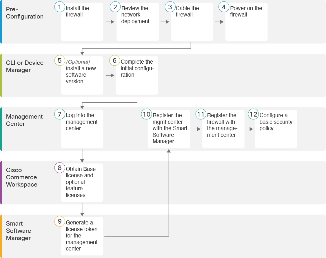
Before You Start
Deploy and perform initial configuration of the management center. See the getting started guide for your model.
The documentation set for this product strives to use bias-free language. For the purposes of this documentation set, bias-free is defined as language that does not imply discrimination based on age, disability, gender, racial identity, ethnic identity, sexual orientation, socioeconomic status, and intersectionality. Exceptions may be present in the documentation due to language that is hardcoded in the user interfaces of the product software, language used based on RFP documentation, or language that is used by a referenced third-party product. Learn more about how Cisco is using Inclusive Language.
Is This Chapter for You?
To see all available applications and managers, see Which Application and Manager is Right for You?. This chapter applies to the threat defense with the management center.
This chapter explains how to manage the threat defense with a management center located on your management network. For remote branch deployment, where the management center resides at a central headquarters, see Threat Defense Deployment with a Remote Management Center.
About the Firewall
The hardware can run either threat defense software or ASA software. Switching between threat defense and ASA requires you to reimage the device. You should also reimage if you need a different software version than is currently installed. See Cisco Secure Firewall ASA and Secure Firewall Threat Defense Reimage Guide.
The firewall runs an underlying operating system called the Secure Firewall eXtensible Operating System (FXOS). The firewall does not support the FXOS Secure Firewall chassis manager; only a limited CLI is supported for troubleshooting purposes. See the Cisco FXOS Troubleshooting Guide for the Firepower 1000/2100 and Secure Firewall 3100/4200 with Firepower Threat Defense for more information.
Privacy Collection Statement—The firewall does not require or actively collect personally identifiable information. However, you can use personally identifiable information in the configuration, for example for usernames. In this case, an administrator might be able to see this information when working with the configuration or when using SNMP.
Deploy and perform initial configuration of the management center. See the getting started guide for your model.
|
|
Pre-Configuration |
Install the firewall. See the hardware installation guide. |
|
|
Pre-Configuration |
|
|
|
Pre-Configuration |
|
|
|
Pre-Configuration |
|
|
|
CLI |
|
|
|
CLI or Device Manager |
|
|
|
Management Center |
|
|
|
Cisco Commerce Workspace |
Buy Base license and optional feature licenses (Obtain Licenses for the Management Center). |
|
|
Smart Software Manager |
Generate a license token for the management center (Obtain Licenses for the Management Center). |
|
|
Management Center |
Register the management center with the Smart Licensing server (Obtain Licenses for the Management Center). |
|
|
Management Center |
|
|
|
Management Center |
The management center communicates with the threat defense on the Management interface.
The dedicated Management interface is a special interface with its own network settings:
By default, the Management 1/1 interface is enabled and configured as a DHCP client. If your network does not include a DHCP server, you can set the Management interface to use a static IP address during initial setup at the console port.
Both the threat defenseand the management center require internet access from their management interfaces for licensing and updates.
 Note |
The management connection is a secure, TLS-1.3-encrypted communication channel between itself and the device. You do not need to run this traffic over an additional encrypted tunnel such as Site-to-Site VPN for security purposes. If the VPN goes down, for example, you will lose your management connection, so we recommend a simple management path. |
You can configure other interfaces after you connect the threat defense to the management center.
The following figure shows a typical network deployment for the firewall where the threat defense, management center, and management computer connect to the management network.
The management network has a path to the internet for licensing and updates.

The following figure shows a typical network deployment for the firewall where:
Inside acts as the internet gateway for Management and for the management center.
Management 1/1 connects to an inside interface through a Layer 2 switch.
The management center and management computer connect to the switch.
This direct connection is allowed because the Management interface has separate routing from the other interfaces on the threat defense.

To cable one of the recommended scenarios on the Secure Firewall 3100, see the following steps.
Note |
Other topologies can be used, and your deployment will vary depending on your basic logical network connectivity, ports, addressing, and configuration requirements. |
Install an SFP for the Management port—The Management port is a 1/10-Gb SFP port that requires an SFP module.
Obtain a console adapter—The Secure Firewall 3100 ships with a DB-9 to RJ-45 serial cable, so you may need to buy a third party DB-9-to-USB serial cable to make the connection.
|
Step 1 |
Install the chassis. See the hardware installation guide. |
|
Step 2 |
Cable for a separate management network: 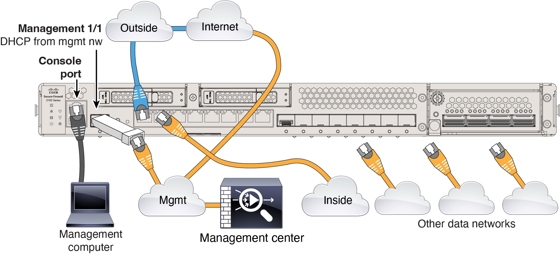
|
|
Step 3 |
Cable for an edge deployment: 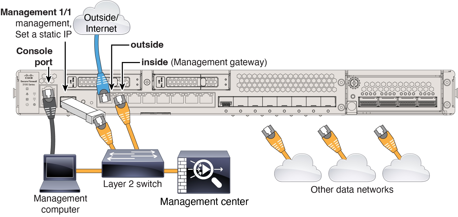
|
System power is controlled by a rocker power switch located on the rear of the firewall. The power switch is implemented as a soft notification switch that supports graceful shutdown of the system to reduce the risk of system software and data corruption.
Note |
The first time you boot up the threat defense, initialization can take approximately 15 to 30 minutes. |
It's important that you provide reliable power for your firewall (for example, using an uninterruptable power supply (UPS)). Loss of power without first shutting down can cause serious file system damage. There are many processes running in the background all the time, and losing power does not allow the graceful shutdown of your system.
|
Step 1 |
Attach the power cord to the firewall, and connect it to an electrical outlet. |
||
|
Step 2 |
Turn the power on using the standard rocker-type power on/off switch located on the rear of the chassis, adjacent to the power cord. |
||
|
Step 3 |
Check the Power LED on the back of the firewall; if it is solid green, the firewall is powered on. 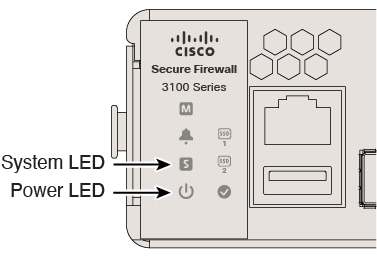
|
||
|
Step 4 |
Check the System LED on the back of the firewall; after it is solid green, the system has passed power-on diagnostics.
|
To check the software version and, if necessary, install a different version, perform these steps. We recommend that you install your target version before you configure the firewall. Alternatively, you can perform an upgrade after you are up and running, but upgrading, which preserves your configuration, may take longer than using this procedure.
What Version Should I Run?
Cisco recommends running a Gold Star release indicated by a gold star next to the release number on the software download page. You can also refer to the release strategy described in https://www.cisco.com/c/en/us/products/collateral/security/firewalls/bulletin-c25-743178.html; for example, this bulletin describes short-term release numbering (with the latest features), long-term release numbering (maintenance releases and patches for a longer period of time), or extra long-term release numbering (maintenance releases and patches for the longest period of time, for government certification).
|
Step 1 |
Connect to the console port. See Access the Threat Defense and FXOS CLI for more information. Log in with the admin user and the default password, Admin123. You connect to the FXOS CLI. The first time you log in, you are prompted to change the password. This password is also used for the threat defense login for SSH.
Example: |
||
|
Step 2 |
At the FXOS CLI, show the running version. scope ssa show app-instance Example: |
||
|
Step 3 |
If you want to install a new version, perform these steps. |
You can complete the threat defense initial configuration using the CLI or device manager.
Set the Management IP address, gateway, and other basic networking settings using the setup wizard. The dedicated Management interface is a special interface with its own network settings. If you do not want to use the Management interface for the manager access, you can use the CLI to configure a data interface instead. You will also configure the management center communication settings. When you perform initial setup using the device manager, all interface configuration completed in the device manager is retained when you switch to the management center for management, in addition to the Management interface and manager access interface settings. Note that other default configuration settings, such as the access control policy, are not retained.
|
Step 1 |
Connect to the threat defense CLI, either from the console port or using SSH to the Management interface, which obtains an IP address from a DHCP server by default. If you intend to change the network settings, we recommend using the console port so you do not get disconnected. The console port connects to the FXOS CLI. The SSH session connects directly to the threat defense CLI. |
||
|
Step 2 |
Log in with the username admin and the password Admin123. At the console port, you connect to the FXOS CLI. The first time you log in to FXOS, you are prompted to change the password. This password is also used for the threat defense login for SSH.
Example: |
||
|
Step 3 |
If you connected to FXOS on the console port, connect to the threat defense CLI. connect ftd Example: |
||
|
Step 4 |
The first time you log in to the threat defense, you are prompted to accept the End User License Agreement (EULA) and, if using an SSH connection, to change the admin password. You are then presented with the CLI setup script.
Defaults or previously entered values appear in brackets. To accept previously entered values, press Enter. See the following guidelines:
Example: |
||
|
Step 5 |
Identify the management center that will manage this threat defense. configure manager add {hostname | IPv4_address | IPv6_address | DONTRESOLVE} reg_key [nat_id]
Example:If the management center is behind a NAT device, enter a unique NAT ID along with the registration key, and specify DONTRESOLVE instead of the hostname, for example: Example:If the threat defense is behind a NAT device, enter a unique NAT ID along with the management center IP address or hostname, for example: Example: |
Register your firewall to the management center.
When you use the device manager for initial setup, the following interfaces are preconfigured in addition to the Management interface and manager access settings. Note that other settings, such as the DHCP server on inside, access control policy, or security zones, are not configured.
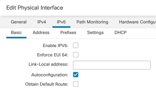
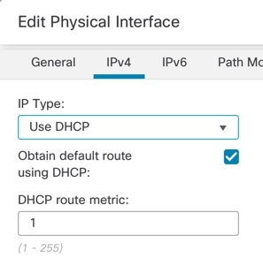
Ethernet 1/1—"outside", IP address from DHCP, IPv6 autoconfiguration
Ethernet 1/2— "inside", 192.168.95.1/24
Default route—Obtained through DHCP on the outside interface
If you perform additional interface-specific configuration within device manager before registering with the management center, then that configuration is preserved.
When you use the CLI, only the Management interface and manager access settings are retained (for example, the default inside interface configuration is not retained).
|
Step 1 |
Log in to the device manager. |
|
Step 2 |
Use the setup wizard when you first log into the device manager to complete the initial configuration. You can optionally skip the setup wizard by clicking Skip device setup at the bottom of the page. After you complete the setup wizard, in addition to the default configuraton for the inside interface (Ethernet1/2), you will have configuration for an outside (Ethernet1/1) interface that will be maintained when you switch to management center management. |
|
Step 3 |
(Might be required) Configure a static IP address for the Management interface. See the Management interface on . If you want to configure a static IP address, for example for an edge deployment where there is not DHCP server on the network yet, be sure to also set the default gateway to be a unique gateway instead of the data interfaces. If you use DHCP, you do not need to configure anything. |
|
Step 4 |
If you want to configure additional interfaces, including an interface other than outside or inside, choose Device, and then click the link in the Interfaces summary. See Configure the Firewall in the Device Manager for more information about configuring interfaces in the device manager. Other device manager configuration will not be retained when you register the device to the management center. |
|
Step 5 |
Choose , and click Proceed to set up the management center management. |
|
Step 6 |
Configure the Management Center/CDO Details. 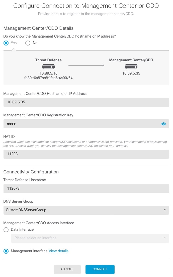
|
|
Step 7 |
Configure the Connectivity Configuration. |
|
Step 8 |
Click Connect. The Registration Status dialog box shows the current status of the switch to the management center. After the Saving Management Center/CDO Registration Settings step, go to the management center, and add the firewall. If you want to cancel the switch to the management center, click Cancel Registration. Otherwise, do not close the device manager browser window until after the Saving Management Center/CDO Registration Settings step. If you do, the process will be paused, and will only resume when you reconnect to the device manager. If you remain connected to the device manager after the Saving Management Center/CDO Registration Settings step, you will eventually see the Successful Connection with Management Center or CDO dialog box, after which you will be disconnected from the device manager. 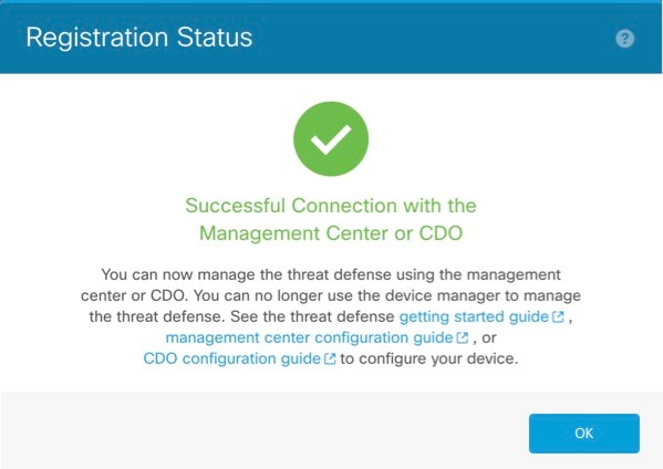
|
Use the management center to configure and monitor the threat defense.
|
Step 1 |
Using a supported browser, enter the following URL. https://fmc_ip_address |
|
Step 2 |
Enter your username and password. |
|
Step 3 |
Click Log In. |
All licenses are supplied to the threat defense by the management center. You can purchase the following licenses:
Essentials—(Required) Essentials license.
IPS—Security Intelligence and Next-Generation IPS
Malware Defense—Malware defense
URL Filtering—URL Filtering
Cisco Secure Client—Secure Client Advantage, Secure Client Premier, or Secure Client VPN Only
Carrier—Diameter, GTP/GPRS, M3UA, SCTP
For a more detailed overview on Cisco Licensing, go to cisco.com/go/licensingguide
Have an account on the Smart Software Manager.
If you do not yet have an account, click the link to set up a new account. The Smart Software Manager lets you create an account for your organization.
Your Smart Software Licensing account must qualify for the Strong Encryption (3DES/AES) license to use some features (enabled using the export-compliance flag).
|
Step 1 |
Make sure your Smart Licensing account contains the available licenses you need. When you bought your device from Cisco or a reseller, your licenses should have been linked to your Smart Software License account. However, if you need to add licenses yourself, use the Search All field on the Cisco Commerce Workspace. 
Choose Products & Services from the results. 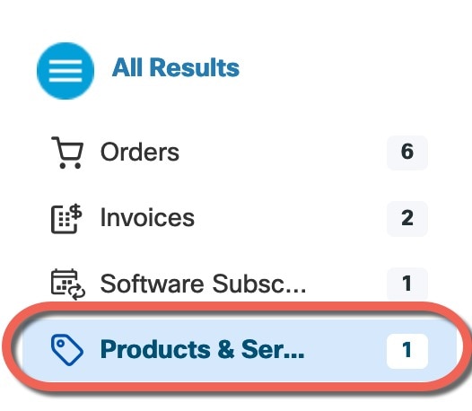
Search for the following license PIDs:
|
||
|
Step 2 |
If you have not already done so, register the management center with the Smart Licensing server. Registering requires you to generate a registration token in the Smart Software Manager. See the Cisco Secure Firewall Management Center Administration Guide for detailed instructions. |
Register the threat defense to the management center manually using the device IP address or hostname.
|
Step 1 |
In the management center, choose . |
||
|
Step 2 |
From the Add drop-down list, choose Add Device. 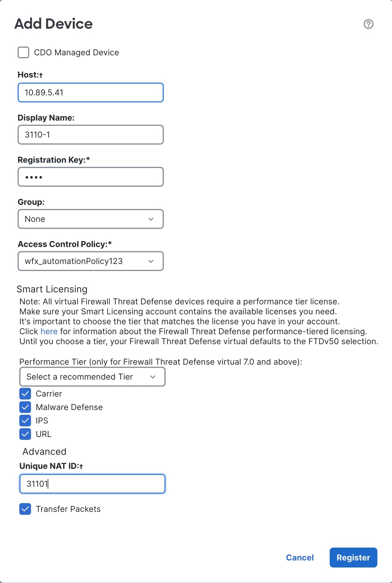
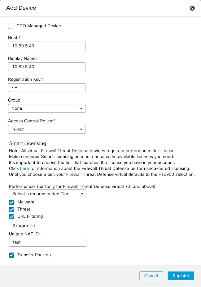
Set the following parameters:
|
||
|
Step 3 |
Click Register, and confirm a successful registration. If the registration succeeds, the device is added to the list. If it fails, you will see an error message. If the threat defense fails to register, check the following items:
For more troubleshooting information, see https://cisco.com/go/fmc-reg-error. |
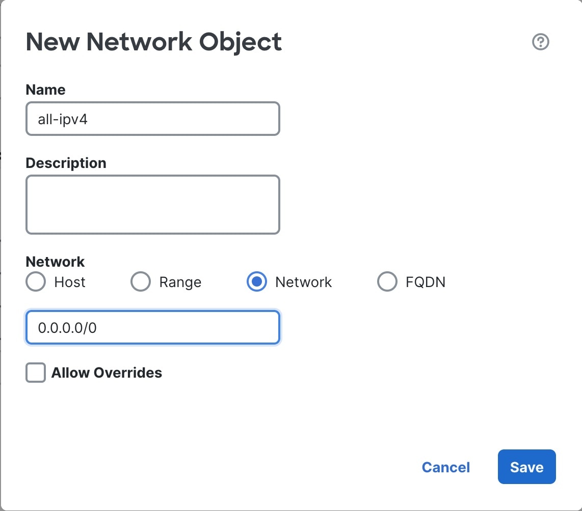
This section describes how to configure a basic security policy with the following settings:
Inside and outside interfaces—Assign a static IP address to the inside interface, and use DHCP for the outside interface.
DHCP server—Use a DHCP server on the inside interface for clients.
Default route—Add a default route through the outside interface.
NAT—Use interface PAT on the outside interface.
Access control—Allow traffic from inside to outside.
To configure a basic security policy, complete the following tasks.
|
|
|
|
|
|
|
|
|
|
|
|
|
|
|
|
|
When you use the device manager for initial setup, the following interfaces are preconfigured:
Ethernet 1/1—"outside", IP address from DHCP, IPv6 autoconfiguration
Ethernet 1/2— "inside", 192.168.95.1/24
Default route—Obtained through DHCP on the outside interface
If you performed additional interface-specific configuration within device manager before registering with the management center, then that configuration is preserved.
In any case, you need to perform additional interface configuration after you register the device. Enable the threat defense interfaces, assign them to security zones, and set the IP addresses. Also configure breakout interfaces. .
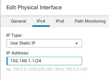
The following example configures a routed mode inside interface with a static address and a routed mode outside interface using DHCP.
|
Step 1 |
Choose , and click the Edit ( |
|
Step 2 |
Click Interfaces. 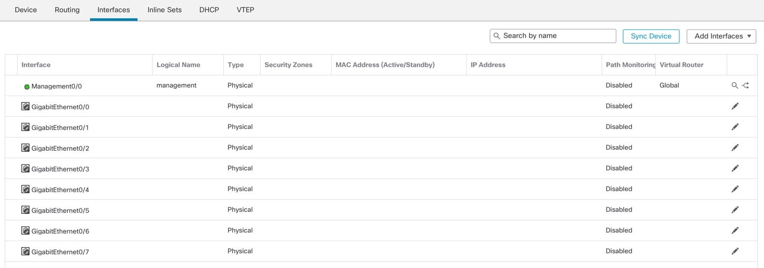
|
|
Step 3 |
To create breakout ports from a 40-Gb or larger interface, click the Break icon for the interface. If you already used the full interface in your configuration, you will have to remove the configuration before you can proceed with the breakout. |
|
Step 4 |
Click Edit ( The General tab appears. 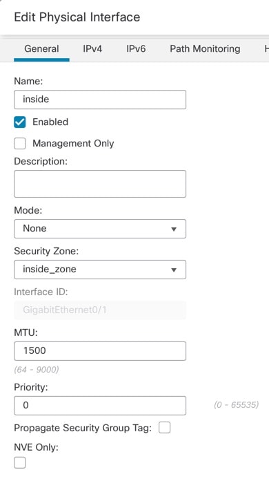
|
|
Step 5 |
Click the Edit ( The General tab appears. 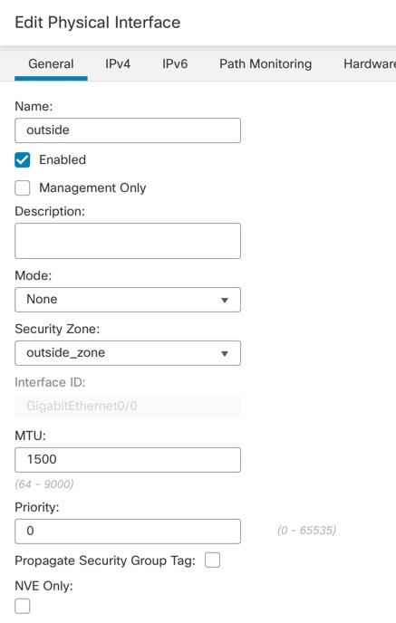
|
|
Step 6 |
Click Save. |
Enable the DHCP server if you want clients to use DHCP to obtain IP addresses from the threat defense.
|
Step 1 |
Choose , and click Edit ( |
|
Step 2 |
Choose . 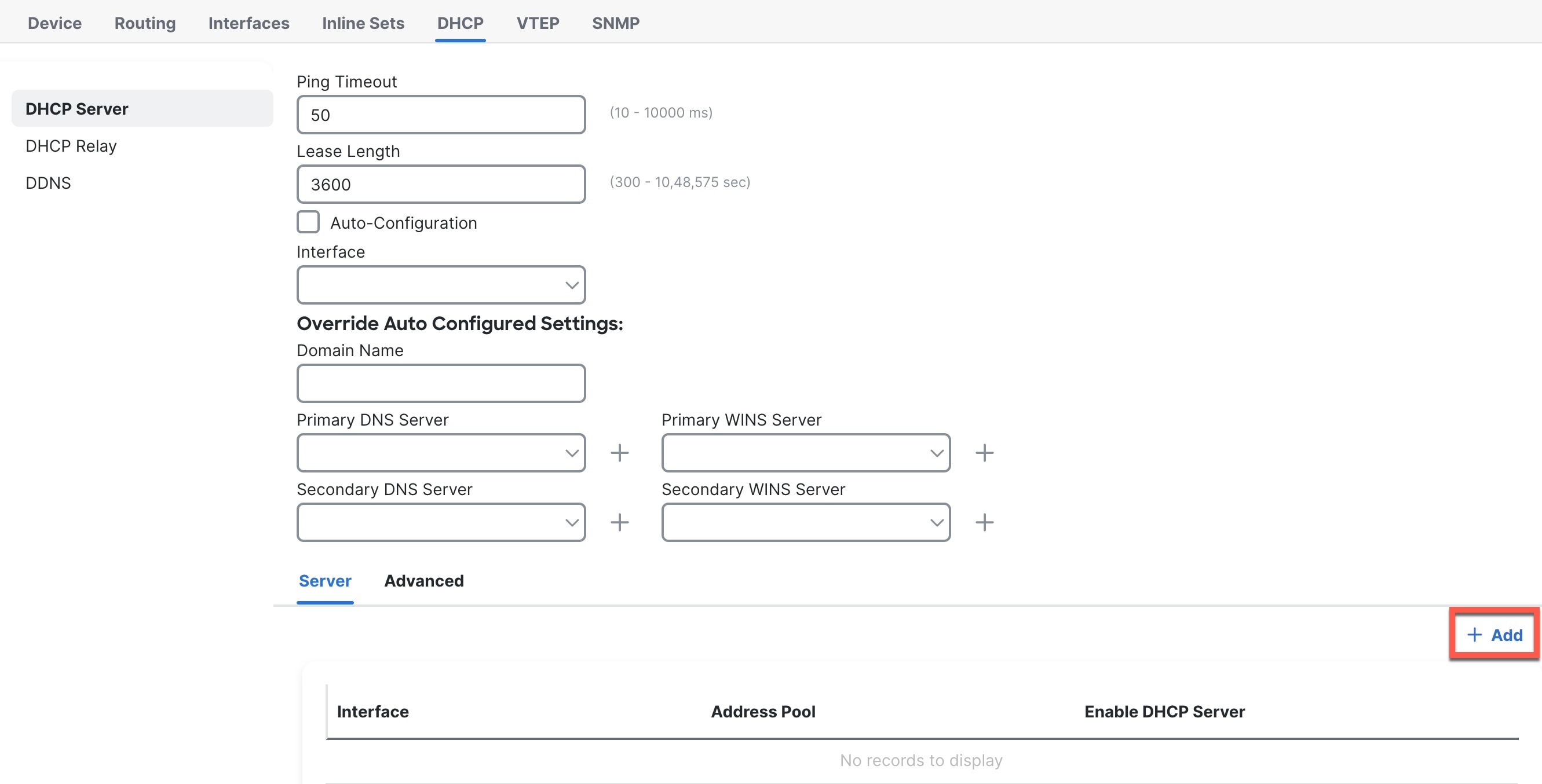
|
|
Step 3 |
On the Server page, click Add, and configure the following options: 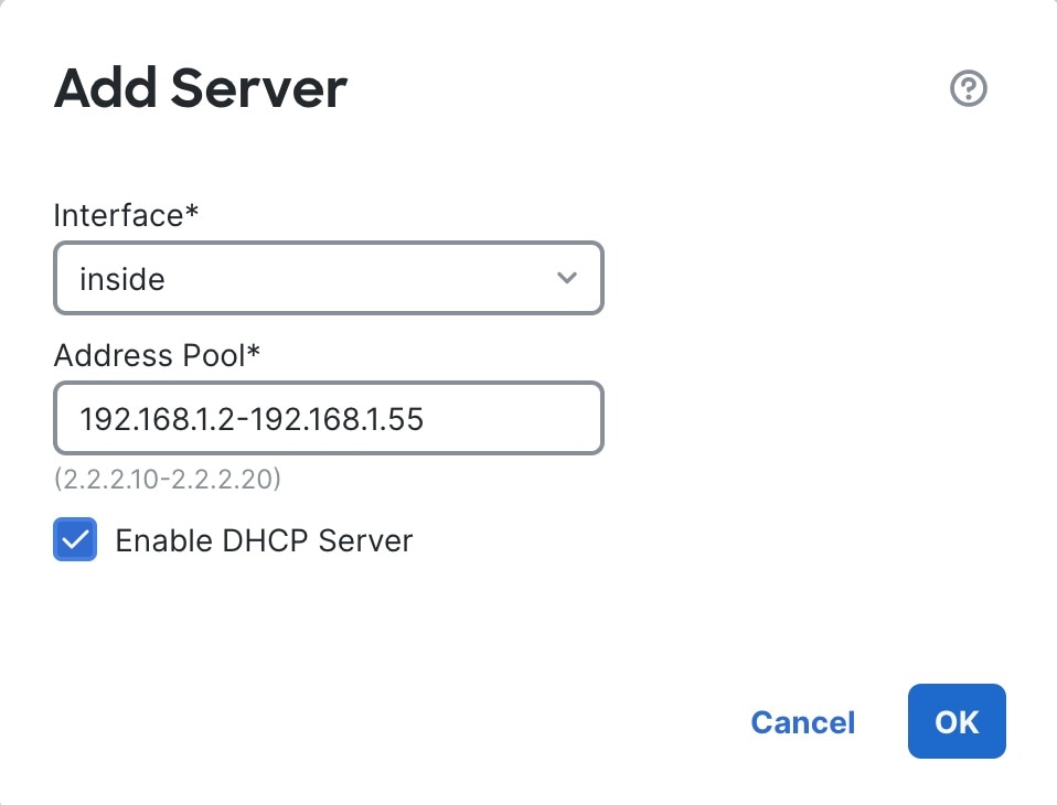
|
|
Step 4 |
Click OK. |
|
Step 5 |
Click Save. |
The default route normally points to the upstream router reachable from the outside interface. If you use DHCP for the outside interface, your device might have already received a default route. If you need to manually add the route, complete this procedure. If you received a default route from the DHCP server, it will show in the IPv4 Routes or IPv6 Routes table on the page.
|
Step 1 |
Choose , and click Edit ( |
|
Step 2 |
Choose . 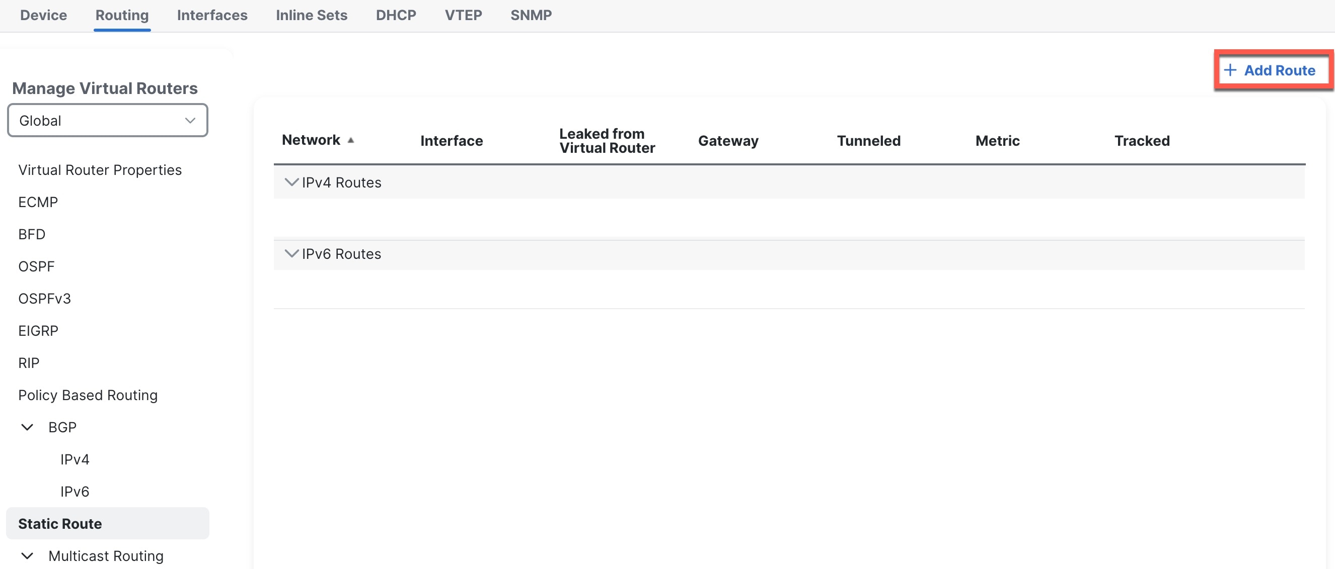
|
|
Step 3 |
Click Add Route, and set the following: 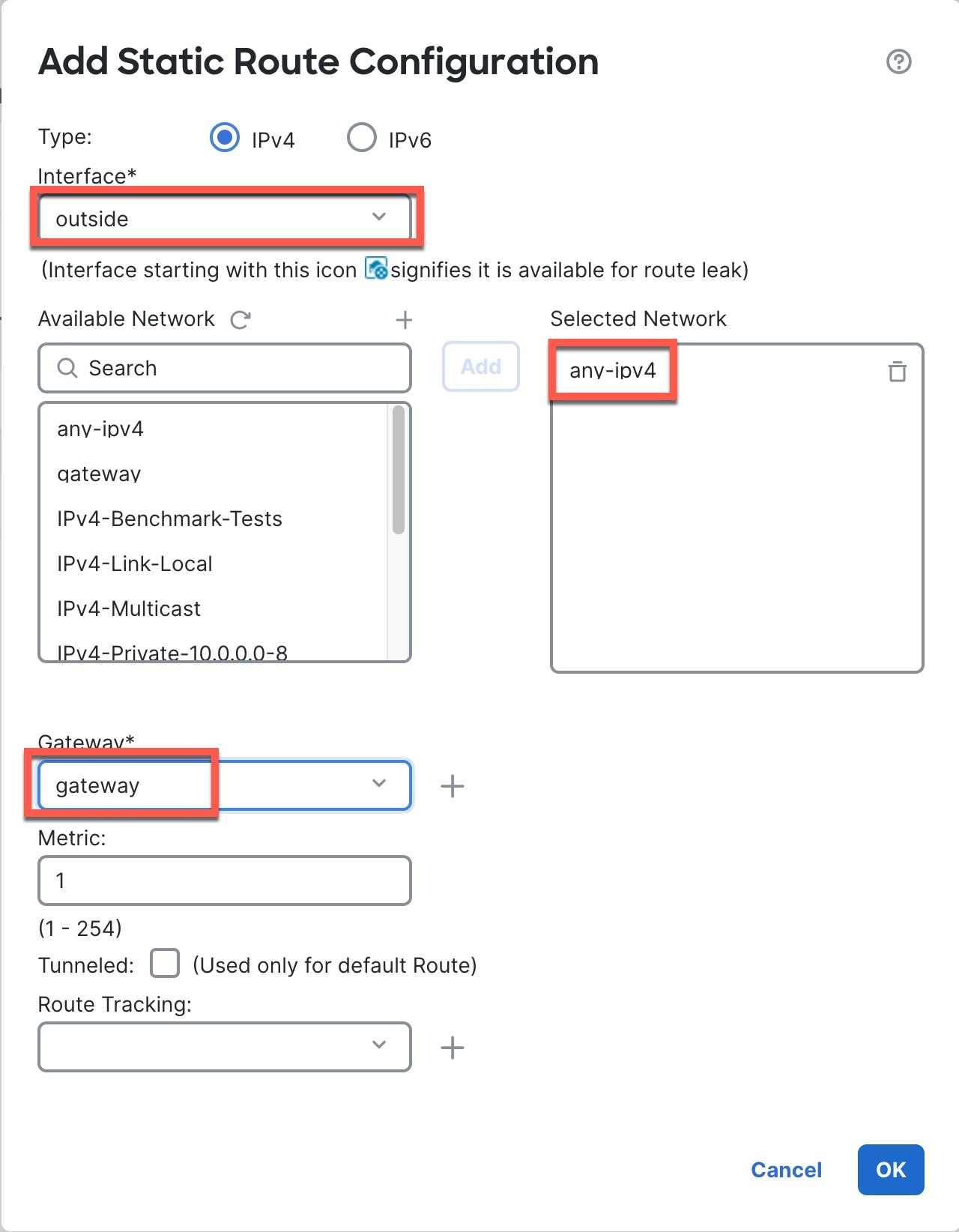
|
|
Step 4 |
Click OK. The route is added to the static route table. |
|
Step 5 |
Click Save. |
A typical NAT rule converts internal addresses to a port on the outside interface IP address. This type of NAT rule is called interface Port Address Translation (PAT).
|
Step 1 |
Choose , and click . |
||
|
Step 2 |
Name the policy, select the device(s) that you want to use the policy, and click Save. 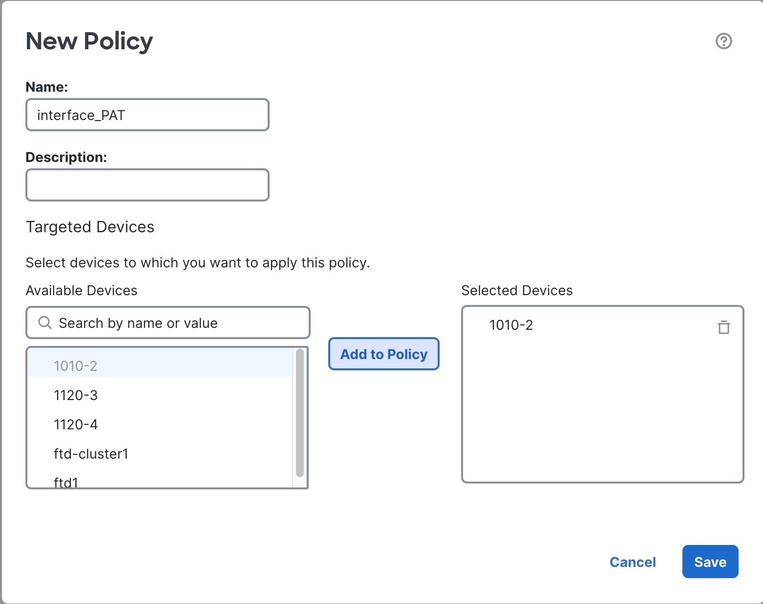
The policy is added the management center. You still have to add rules to the policy. 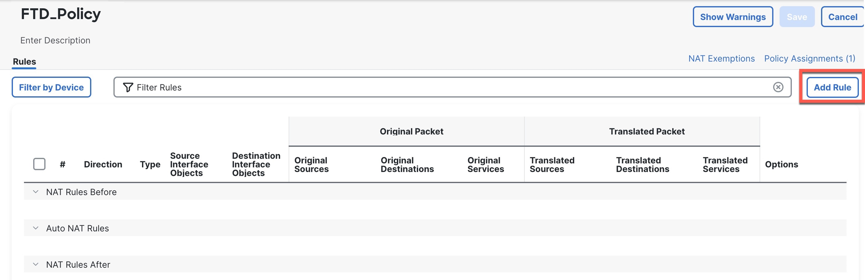
|
||
|
Step 3 |
Click Add Rule. The Add NAT Rule dialog box appears. |
||
|
Step 4 |
Configure the basic rule options: 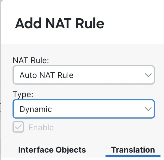
|
||
|
Step 5 |
On the Interface Objects page, add the outside zone from the Available Interface Objects area to the Destination Interface Objects area. 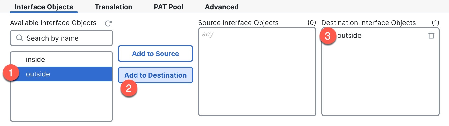
|
||
|
Step 6 |
On the Translation page, configure the following options: 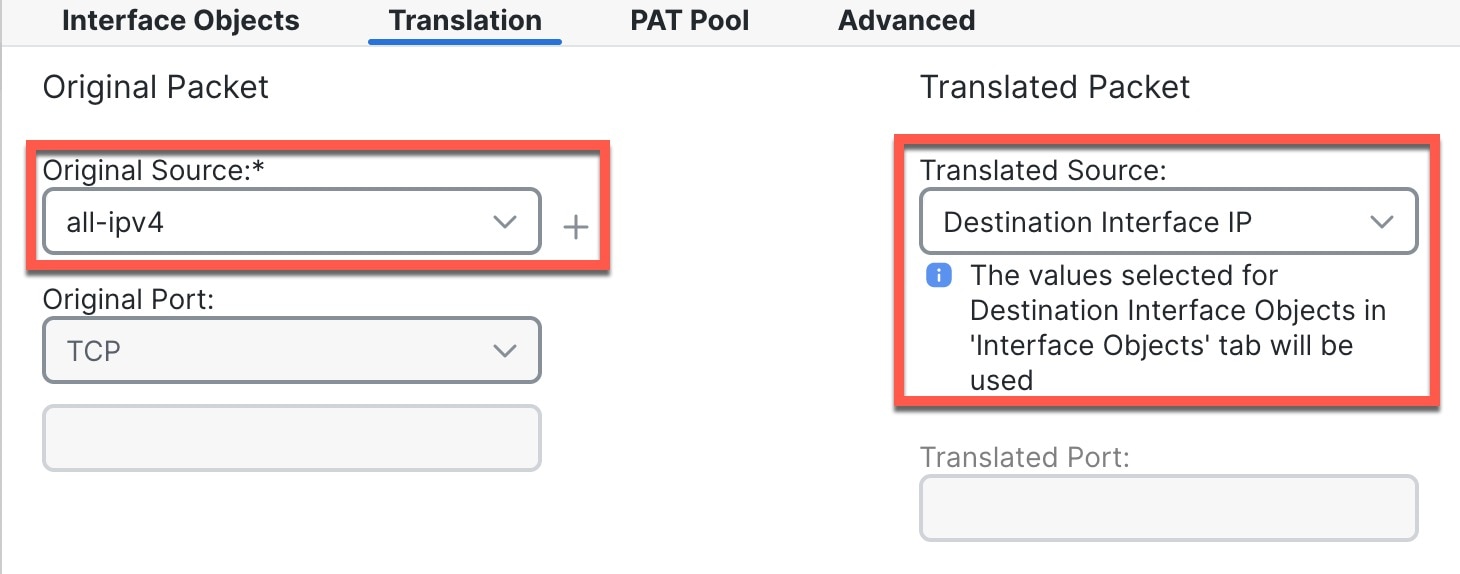
|
||
|
Step 7 |
Click Save to add the rule. The rule is saved to the Rules table. |
||
|
Step 8 |
Click Save on the NAT page to save your changes. |
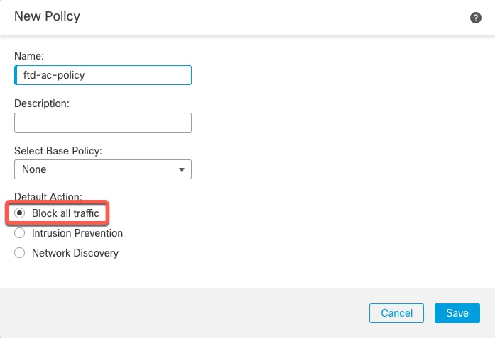
If you created a basic Block all traffic access control policy when you registered the threat defense, then you need to add rules to the policy to allow traffic through the device. The following procedure adds a rule to allow traffic from the inside zone to the outside zone. If you have other zones, be sure to add rules allowing traffic to the appropriate networks.
|
Step 1 |
Choose , and click Edit ( |
|
Step 2 |
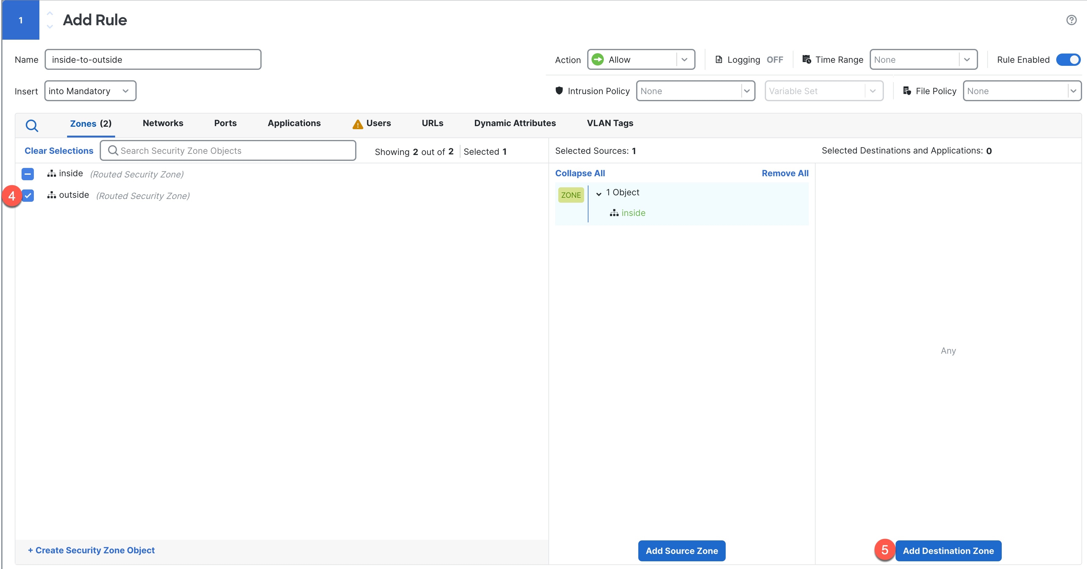
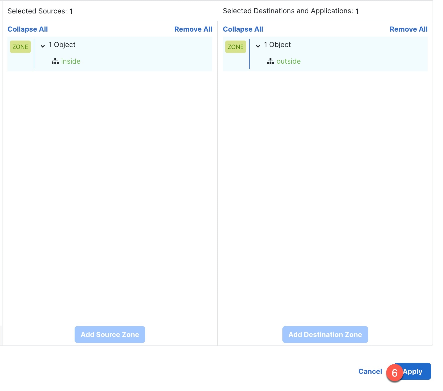
Click Add Rule, and set the following parameters: 
Leave the other settings as is. |
|
Step 3 |
Click Apply. The rule is added to the Rules table. |
|
Step 4 |
Click Save. |
Deploy the configuration changes to the threat defense; none of your changes are active on the device until you deploy them.
|
Step 1 |
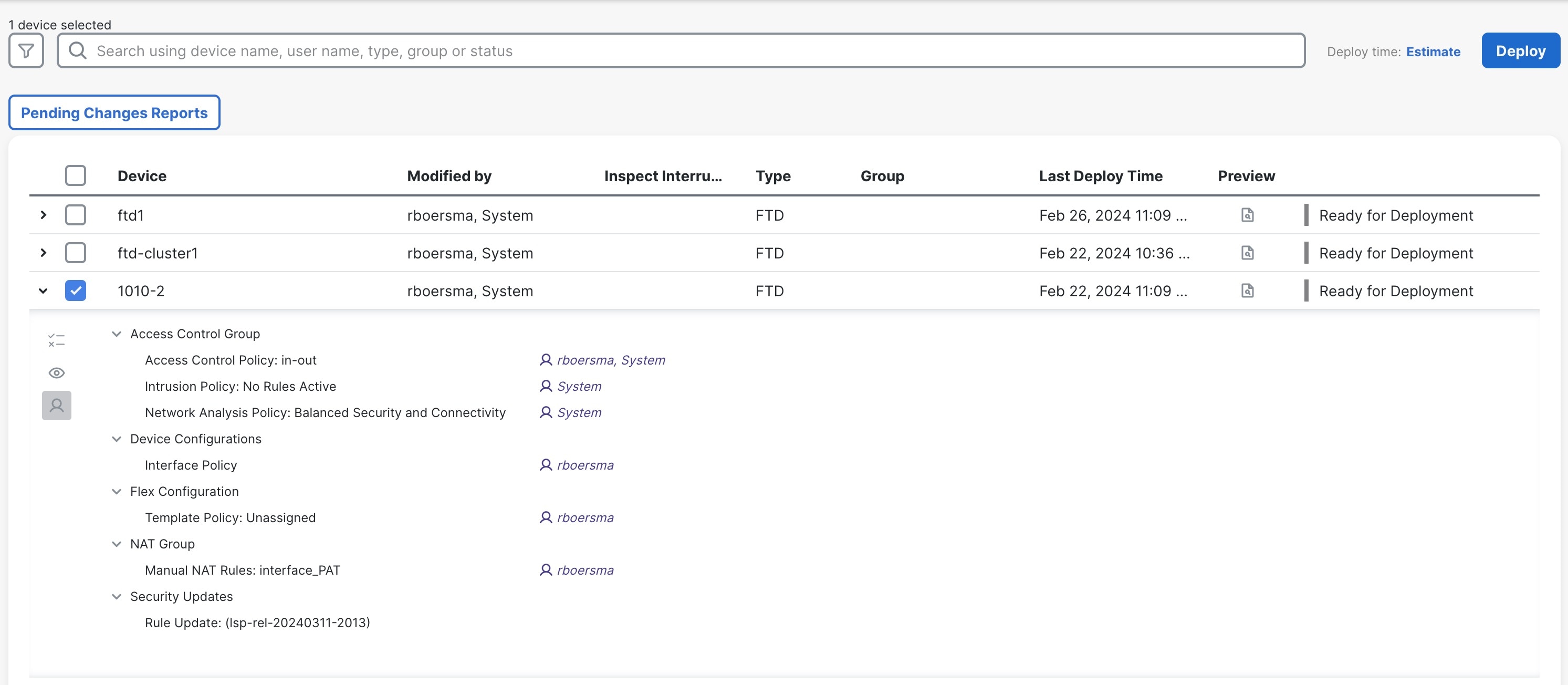
Click Deploy in the upper right. 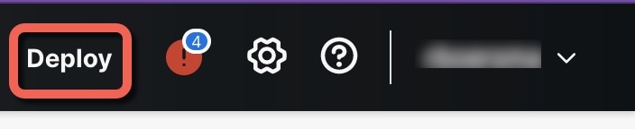
|
|
Step 2 |
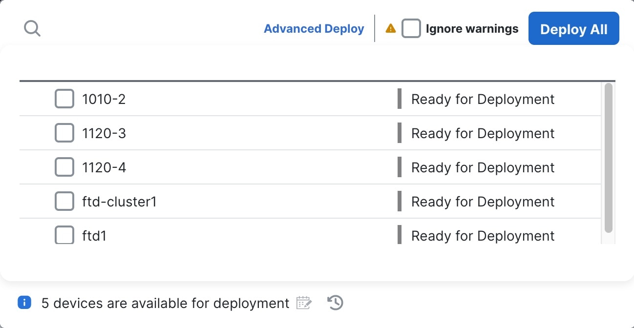
For a quick deployment, check specific devices and then click Deploy, or click Deploy All to deploy to all devices. Otherwise, for additional deployment options, click Advanced Deploy. 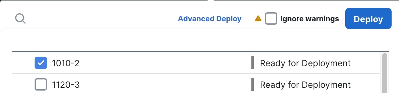
|
|
Step 3 |
Ensure that the deployment succeeds. Click the icon to the right of the Deploy button in the menu bar to see status for deployments. 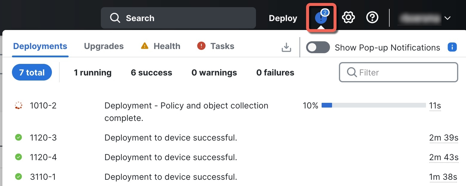
|
Use the command-line interface (CLI) to set up the system and do basic system troubleshooting. You cannot configure policies through a CLI session. You can access the CLI by connecting to the console port.
You can also access the FXOS CLI for troubleshooting purposes.
Note |
You can alternatively SSH to the Management interface of the threat defense device. Unlike a console session, the SSH session defaults to the threat defense CLI, from which you can connect to the FXOS CLI using the connect fxos command. You can later connect to the address on a data interface if you open the interface for SSH connections. SSH access to data interfaces is disabled by default. This procedure describes console port access, which defaults to the FXOS CLI. |
|
Step 1 |
To log into the CLI, connect your management computer to the console port. The Secure Firewall 3100 ships with a DB-9 to RJ-45 serial cable, so you may need to buy a third party DB-9-to-USB serial cable to make the connection. Be sure to install any necessary USB serial drivers for your operating system. The console port defaults to the FXOS CLI. Use the following serial settings:
You connect to the FXOS CLI. Log in to the CLI using the admin username and the password you set at initial setup (the default is Admin123). Example: |
|
Step 2 |
Access the threat defense CLI. connect ftd Example:After logging in, for information on the commands available in the CLI, enter help or ? . For usage information, see Cisco Secure Firewall Threat Defense Command Reference. |
|
Step 3 |
To exit the threat defense CLI, enter the exit or logout command. This command returns you to the FXOS CLI prompt. For information on the commands available in the FXOS CLI, enter ? . Example: |
It's important that you shut down your system properly. Simply unplugging the power or pressing the power switch can cause serious file system damage. Remember that there are many processes running in the background all the time, and unplugging or shutting off the power does not allow the graceful shutdown of your firewall system.
You can power off the device using the management center device management page, or you can use the FXOS CLI.
It's important that you shut down your system properly. Simply unplugging the power or pressing the power switch can cause serious file system damage. Remember that there are many processes running in the background all the time, and unplugging or shutting off the power does not allow the graceful shutdown of your firewall.
You can shut down your system properly using the management center.
|
Step 1 |
Choose . |
|
Step 2 |
Next to the device that you want to restart, click Edit ( |
|
Step 3 |
Click the Device tab. |
|
Step 4 |
Click Shut Down Device
( |
|
Step 5 |
When prompted, confirm that you want to shut down the device. |
|
Step 6 |
If you have a console connection to the firewall, monitor the system prompts as the firewall shuts down. You will see the following prompt: If you do not have a console connection, wait approximately 3 minutes to ensure the system has shut down. |
|
Step 7 |
You can now turn off the power switch and unplug the power to physically remove power from the chassis if necessary. |
You can use the FXOS CLI to safely shut down the system and power off the device. You access the CLI by connecting to the console port; see Access the Threat Defense and FXOS CLI.
|
Step 1 |
In the FXOS CLI, connect to local-mgmt: firepower # connect local-mgmt |
|
Step 2 |
Issue the shutdown command: firepower(local-mgmt) # shutdown Example: |
|
Step 3 |
Monitor the system prompts as the firewall shuts down. You will see the following prompt: |
|
Step 4 |
You can now turn off the power switch and unplug the power to physically remove power from the chassis if necessary. |
To continue configuring your threat defense, see the documents available for your software version at Navigating the Cisco Secure Firewall Threat Defense Documentation.
For information related to using the management center, see the Cisco Secure Firewall Management Center Device Configuration Guide.
 )
)
 Feedback