About BFD Routing
BFD is a detection protocol designed to provide fast forwarding path failure detection times for all media types, encapsulations, topologies, and routing protocols. BFD operates in a unicast, point-to-point mode on top of any data protocol being forwarded between two systems. Packets are carried in the payload of the encapsulating protocol appropriate for the media and the network.
BFD provides a consistent failure detection method for network administrators in addition to fast forwarding path failure detection. Because the network administrator can use BFD to detect forwarding path failures at a uniform rate, rather than the variable rates for different routing protocol hello mechanisms, network profiling and planning are easier and reconvergence time is consistent and predictable.
BFD Asynchronous Mode and Echo Function
BFD can operate in asynchronous mode with or without the echo function enabled.
- Asynchronous Mode
-
In asynchronous mode, the systems periodically send BFD control packets to one another, and if a number of those packets in a row are not received by the other system, the session is declared to be down. Pure asynchronous mode (without the Echo function) is useful because it requires half as many packets to achieve a particular detection time as the Echo function requires.
- BFD Echo Function
-
The BFD echo function sends echo packets from the forwarding engine to the directly-connected single-hop BFD neighbor. The echo packets are sent by the forwarding engine and forwarded back along the same path to perform detection. The BFD session at the other end does not participate in the actual forwarding of the echo packets. Because the echo function and the forwarding engine are responsible for the detection process, the number of BFD control packets that are sent out between BFD neighbors is reduced. And also because the forwarding engine is testing the forwarding path on the remote neighbor system without involving the remote system, the inter-packet delay variance is improved. This results in quicker failure detection times.
When the echo function is enabled, BFD can use the slow timer to slow down the asynchronous session and reduce the number of BFD control packets that are sent between BFD neighbors, which reduces processing overhead while at the same time delivering faster failure detection.

Note
The echo function is not supported for IPv4 multi-hop or IPv6 single-hop BFD neighbors.
You can enable BFD at the interface and routing protocol levels. You must configure BFD on both systems (BFD peers). After you enable BFD on the interfaces and at the router level for the appropriate routing protocols, a BFD session is created, BFD timers are negotiated, and the BFD peers begin to send BFD control packets to each other at the negotiated level.
BFD Session Establishment
The following example shows the ASA and a neighboring router running Border Gateway Protocol (BGP). At the time when both devices come up, there is no BFD session established between them.
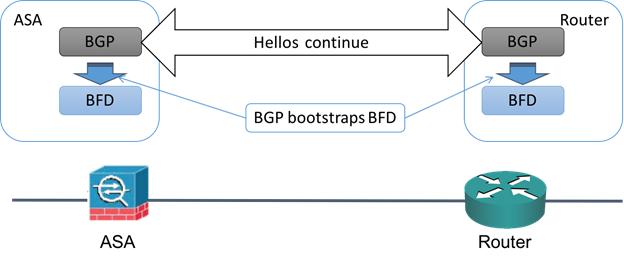
After BGP identifies its BGP neighbor, it bootstraps the BFD process with the IP address of the neighbor. BFD does not discover its peers dynamically. It relies on the configured routing protocols to tell it which IP addresses to use and which peer relationships to form.
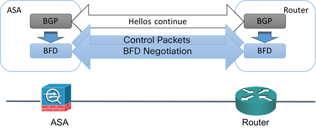
The BFD on the router and the BFD on the ASA form a BFD control packet and start sending the packets to each other at a one-second interval until the BFD session is established. The initial control packets from either system are very similar, for example, the Vers, Diag, H, D, P, and F bits are all set to zero, and the State is set to Down. The My Discriminator field is set to a value that is unique on the transmitting device. The Your Discriminator field is set to zero because the BFD session has not yet been established. The TX and RX timers are set to the values found in the configuration of the device.
After the remote BFD device receives a BFD control packet during the session initiation phase, it copies the value of the My Discriminator field into its own Your Discriminator field and the transition from Down state to Init state and then eventually to Up state occurs. Once both systems see their own Discriminators in each other's control packets, the session is officially established.
The following illustration shows the established BFD connection.
BFD Timer Negotiation
BFD devices must negotiate the BFD timers to control and synchronize the send rate of BFD control packets. A device needs to ensure the following before it can negotiate a BFD timer:
-
That its peer device saw the packet containing the proposed timers of the local device
-
That it never sends BFD control packets faster than the peer is configured to receive them
-
That the peer never sends BFD control packets faster than the local system is configured to receive them
The setting of the Your Discriminator field and the H bit are sufficient to let the local device that the remote device has seen its packets during the initial timer exchange. After receiving a BFD control packet, each system takes the Required Min RX Interval and compares it to its own Desired Min TX Interval, and then takes the greater (slower) of the two values and uses it as the transmission rate for its BFD packets. The slower of the two systems determines the transmission rate.
When these timers have been negotiated, they can be renegotiated at any time during the session without causing a session reset. The device that changes its timers sets the P bit on all subsequent BFD control packets until it receives a BFD control packet with the F bit set from the remote system. This exchange of bits guards against packets that might otherwise be lost in transit.
Note |
The setting of the F bit by the remote system does not mean that it accepts the newly proposed timers. It indicates that the remote system has seen the packets in which the timers were changed. |
BFD Failure Detection
When the BFD session and timers have been negotiated, the BFD peers send BFD control packets to each other at the negotiated interval. These control packets act as a heartbeat that is very similar to IGP Hello protocol except that the rate is more accelerated.
As long as each BFD peer receives a BFD control packet within the configured detection interval (Required Minimum RX Interval), the BFD session stays up and any routing protocol associated with BFD maintains its adjacencies. If a BFD peer does not receive a control packet within this interval, it informs any clients participating in that BFD session about the failure. The routing protocol determines the appropriate response to that information. The typical response is to terminate the routing protocol peering session and reconverge and thus bypass a failed peer.
Each time a BFD peer successfully receives a BFD control packet in a BFD session, the detection timer for that session is reset to zero. Thus the failure detection is dependent on received packets and NOT when the receiver last transmitted a packet.
BFD Deployment Scenarios
The following describes how BFD operates in these specific scenarios.
- Failover
-
In a failover scenario, BFD sessions are established and maintained between the active unit and the neighbor unit. Standby units do not maintain any BFD sessions with the neighbors. When a failover happens, the new active unit must initiate session establishment with the neighbor because session information is not synched between active and standby units.
For a graceful restart/NSF scenario, the client (BGP IPv4/IPv6) is responsible for notifying its neighbor about the event. When the neighbor receives the information, it keeps the RIB table until failover is complete. During failover, the BFD and the BGP sessions go down on the device. When the failover is complete, a new BFD session between the neighbors is established when the BGP session comes up.
- Spanned EtherChannel and L2 Cluster
-
In a Spanned EtherChannel cluster scenario, the BFD session is established and maintained between the primary unit and its neighbor. Subordinate units do not maintain any BFD sessions with the neighbors. If a BFD packet is routed to the subordinate unit because of load balancing on the switch, the subordinate unit must forward this packet to the primary unit through the cluster link. When a cluster switchover happens, the new primary unit must initiate session establishment with the neighbor because session information is not synched between primary and subordinate units.
- Individual Interface Mode and L3 Cluster
-
In an individual interface mode cluster scenario, individual units maintain their BFD sessions with their neighbors.
 Feedback