Cisco SD-WAN Cloud onRamp for Colocation Solution Requirements
The following are the hardware, software, Cloud OnRamp for Colocation cluster, and cabling requirements for deploying Cisco SD-WAN Cloud onRamp for Colocation solution.
Hardware Requirements
The following table lists the hardware requirements:
|
Feature Name |
Release Information |
Description |
|
Support for Cisco Cloud Services Platform, CSP-5456 |
Cisco SD-WAN Release 20.4.1 |
Starting from this release, Cisco CSP-5456 is supported on the Cloud onRamp for Colocation solution. The CSP-5456 offers a higher capacity of 56 cores, which maximizes the placement of VNFs in service chains. |
|
Components |
Hardware Requirements |
||||||||
|---|---|---|---|---|---|---|---|---|---|
|
Compute platform |
CSP- 5444 and CSP-5456 |
||||||||
|
Physical form factor |
Cisco UCS C240 M5SX (2RU) |
||||||||
|
Processor cores |
CSP-5444: 44 physical cores CSP-5456: 56 physical cores |
||||||||
|
PCIe NIC slots |
6 |
||||||||
|
Disk |
8 * 1.2 TB = 9.6 TB |
||||||||
|
Disk slots |
26 (24 useable) |
||||||||
|
Memory |
192 GB of RAM |
||||||||
|
RAID |
12-Gbps SAS HW controller, 4 GB flash-backed write cache (FBWC), RAID 10. |
||||||||
|
Base Networking |
4x1PCIE card in M5 6x1GE Intel i350 ports, 2x1GE LoM
|
||||||||
|
Network Interface Cards (NIC) |
2xIntel X520 2-port 10G (Niantic) and Intel XL710 4-port 10G SFP+ (Fortville)
|
||||||||
|
Processors (2) |
2xIntel Xeon Gold 6152 Series |
||||||||
|
Power Supplies |
Dual power |
||||||||
| Network fabric |
Catalyst 9500-40X
Supports forty10G ports and two 40G ports |
||||||||
| Catalyst 9500-48Y4C Supports forty-eight 1G/10G/25G ports and four 40G/100G ports |
|||||||||
|
Management network |
Any switch with sufficient number of 1G ports and port channel feature can be used as the management switch. Two switches are recommended to support hardware and link redundancy. |
Software Requirements
The following table lists the software requirements:
|
Components |
Software Requirements |
|---|---|
|
Virtualization infrastructure software |
Cisco NFVIS Cloud OnRamp for Colocation See Release Notes for Cisco SD-WAN Cloud OnRamp for Colocation Solution. |
|
Orchestration |
Cisco vManage See
|
Supported Platforms and Firmware
The following table lists the supported platform and firmware versions of Cisco NFVIS:
|
Platform |
Firmware |
Version |
|---|---|---|
|
CSP-5444, CSP-5456 |
BIOS |
C240M5.4.2.2b.0.0613220203 |
| CIMC | 4.2(2a) |
To upgrade a CIMC version, see the Cisco Host Upgrade Utility User Guide.
 Note |
We recommend that you reach out the Technical Assistance Center (TAC) when upgrading the CIMC version. |
Wiring Requirements
|
Feature Name |
Release Information |
Description |
|---|---|---|
|
Support for SVL Port Configuration on 100G Interfaces |
Cisco IOS XE Release 17.8.1a Cisco vManage Release 20.8.1 Cisco NFVIS Release 4.8.1 |
With this feature, you can configure SVL ports on 100-G Ethernet interfaces of Cisco Catalyst 9500-48Y4C switches, thus ensuring a high level of performance and throughput. |
|
Common Port Channel for Ingress and Egress Traffic |
Cisco vManage Release 20.9.1 Cisco NFVIS Release 4.9.1 |
This feature introduces a common port channel for ingress and egress traffic from the time of creation of a colocation cluster. This feature facilitates an uninterrupted traffic flow by bringing all connected member links into a single port channel, which in turn load balances the traffic. The ingress port number is used to create a single port channel. |
The solution supports both flexible and prescriptive connections between Cisco CSP devices and Cisco Catalyst 9500 switches.
Prescriptive Connections
Prescriptive connections are supported on both Cisco Catalyst 9500-48Y4C and Cisco Catalyst 9500-40X switches.
Ensure that you connect the SVL ports and uplink ports of the Catalyst 9500 switches based on the following information:
Cisco Catalyst 9500-40X
-
Stackwise Virtual Switch Link (SVL) ports: 1/0/38-1/0/40, and 2/0/38-2/0/40
-
Uplink ports: 1/0/36, 2/0/36 (input VLAN handoff) and 1/0/37, 2/0/37 (output VLAN handoff)
Cisco Catalyst 9500-48Y4C
The following image shows the high-level design of the physical connectivity for Cisco Catalyst 9500-40X switch.
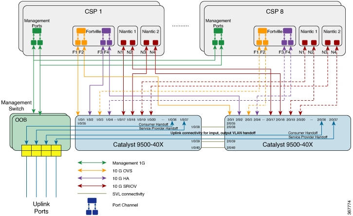
In the preceding topology, each CSP has two 1-GB management ports configured as port channels to the OOB management switch. Each of the Cisco Catalyst 9500-40X switch is connected to the 1-GB port. This connectivity requires two ports on the Management switch per cloud onramp for colocation. The service provider handoff is connected to 10-GB ports on this switch. All service providers ports are trunked into the Cisco Catalyst 9500-40X switch. All the VLANs are configured on all ports of Cisco Catalyst 9500-40X switch.
You can similarly connect the CSP devices with the Cisco Catalyst 9500-48Y4C switches in a prescribed manner.
Note |
The management switches are not orchestrated and must be manually provisioned. Although the management switches are not orchestrated, ensure that the management switches and devices are connected as per the defined connections. |
Flexible Connections
Flexible connections are supported on Cisco Catalyst 9500-40X and Cisco Catalyst 9500-48Y4C switches. For flexible connections:
-
Exactly two Niantic cards and one Fortville card should be inserted into a Cisco CSP device in any riser card slot.
Note
If you insert the Niantic cards into slots other than riser slots 1 and 4, and Fortville card into any slot other than slot 2, then clean install Cisco NFVIS on the Cisco CSP device after connecting all the cards.
-
All data ports on a Cisco CSP device connected to any available ports on Cisco Catalyst 9500-40X or Cisco Catalyst 9500-48Y4C switches.
Note
Ensure that you connect all ports on Cisco CSP devices and they are connected in a redundant manner to the primary and secondary switch ports. If all Cisco CSP ports are not connected, the cluster activation process fails.
-
Connect SVL ports anywhere between 1/0/1-1/0/48 and 2/0/1-2/0/48 or 1/0/48-1/0/52 and 2/0/48-2/0/52.
-
Connect Uplink ports anywhere between 1/0/1-1/0/48 and 2/0/1-2/0/48 for 10G/25G throughput, or between 1/0/49-1/0/52 and 2/0/49-2/0/52 for 40G/100G throughput
-
Connect all Niantic and Fortville ports of a Cisco CSP device for redundancy. For example, if Niantic ports are plugged into riser slots 1 and 2 and Fortville ports are plugged into riser slot 4, then you can connect the Cisco CSP interfaces to the switches in either of the following ways:
-
Primary switch: eth1-1, eth2-1, eth4-1, eth4-3
Secondary Switch: eth1-2, eth2-2, eth4-2, eth4-4
-
Primary switch: eth1-2, eth2-1, eth4-1, eth4-2
Secondary Switch: eth1-1, eth2-2, eth4-3, eth4-4
-
-
Connect Physical Network functions (PNFs) to any available Cisco Catalyst 9500-40X or Cisco Catalyst 9500-48Y4C switches
-
Connect each of the Cisco Catalyst 9500-40X or Cisco Catalyst 9500-48Y4C switch to the 1-GB management port. Each Cisco CSP device has two 1-GB management ports configured as port channels to the OOB management switch. The management switches are not orchestrated through Cisco vManage. Therefore, ensure that you connect the management switches and management ports as shown in the following image.
The following image shows the flexible connectivity between the Cisco CSP devices and Cisco Catalyst 9500-48Y4C switches where the SVL and uplink ports are connected to the default ports.

 Feedback