Overview of Cisco Catalyst 8300 Series Edge uCPE

The Cisco Catalyst 8300 Series Edge universal Customer Premises Equipment (uCPE) is a purpose-built x86 platform that is designed for branch virtualization. It enables device consolidation across network and security functions, improves operational flexibility and service agility, simplifies network operations, and results in reduced deployment times and fewer truck rolls for delivery of add-on services.

Cisco Catalyst 8300 Series Edge uCPE Chassis

Figure 1. Chassis Front Panel

1

Status LEDs

2

Physical Interface Module (PIM) slot for CAT 7 LTE or 5G cellular connectivity (for future use)

3

Network Interface Module (NIM) slot for additional L2/L3 MACsec, Power over Ethernet (PoE) ports (for future use)

4

E1.S disk slot

(For future use)

5

U.2 2.5-inch disk slots x 2

6

Radior Frequency Identification (RFID)

7

M.2 disk slot (75 GB USB M.2, 600 GB or 2 TB NVMe disk)
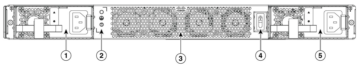
Figure 2. Chassis- Bezel Side

1

PSU Slot

2

GND lug or ground point

3

Fan tray

(Visible through chassis)

4

Chassis on/off switch

5

PSU slot

Figure 3. Chassis- Internal

1

DIMM slots x 4

2

Fan Tray

Location of Labels on Cisco Catalyst 8300 Series Edge uCPE

The figure below shows the location of the labels on the Cisco Catalyst 8300 Series Edge uCPE. Labels are located at the same location on all the Cisco Catalyst 8300 Series Edge uCPE.

Figure 4. Product Lables

1

Product label location

Figure 5. Compliance label

1

Compliance label location

Hardware Features

  • USB-A 3.0 and Micro-USB Console port: You can use this port to connect a mouse, keyboard, or any other USB device. Using a USB hub, you can connect more than one USB device to this port. Because this port is backward compatible, you can also use an older version of USB device.

  • Front panel Gigabit Ethernet ports: There are four SFP ports and four copper ports (GE0 supports 802.3bt POE standard and UPOE+ PD if compliant with 802.3bt).

  • M.2 storage module: This is a high capacity storage component. The OS is installable in this module. The storage capacity of this module is upgradeable. The storage capacity is 75 GB USB M.2 or 600 GB NVME M.2 or 2 TB NVME M.2.

  • CPU: Ice Lake 20-core HCC with all core turbo frequency of 2.5 GHz, D2796NFT base frequency is 2 GHz and maximum turbo frequency of 3.1 GHz.

  • Dual In-Line Memory Modules (DIMMs): Stores the running configuration and routing tables and is used for packet buffering by the network interfaces.


    Note


    • Supports maximum of 128 GB of main memory with 4 x 32 GB DDR4 DIMMs.

    • Four DIMM slots, numbered from 0 to 3 with a frequency of 3200 MHz.

    • Uses DDR4 DIMMs for the main memory.

    • Memory DIMM combinations allowed: 1 x 32GB, 2 x 16GB, 2 x 32GB, 4 x 16GB, 4 x 32GB.


  • Network Interface Module (NIM): The device supports one NIM when you need additional ports. See data sheet for supported NIMs.

  • Pluggable Interface Module (PIM): The device supports one PIM for cellular connectivity. See data sheet for supported PIMs.


    Note


    For proper thermal functioning of the system, install and provision a functional module with a blank filler for all module slots or optional components (PIM, NIM, E1.S, M.2 and U.2) that do not have a functional module installed.


Status Indicators and LEDs for Gigabit Ethernet Ports

The front panel Gigabit Ethernet ports have eight ports: four RJ45 ports and four SFP ports.

Figure 6. Status and LED indicators

1

LED indicator for power supply

2

LED indicator for device status

3

LED indicator for environmental status

4

LED indicator for blue beacon

5

CPU Activity

6

Link

7

Activity for 0/0 - 0/2 copper ports

8

Link for GEO/0~0/2

9

Link/LOS for SFP 0/3~0/6

Figure 7. Activity and Fault indicators

1

E1.S Activity

2

Hazard fault symbol

3

SSD Activity for U.2 slot

LED Definition

Color

Description

GE0-2 RJ45 Activity LED

Green

Ethernet port 0/1/2 Activity LED Off: No activity blinking green : ethernet activity detected

GE0-2 RJ45 Link LED

Green

Ethernet port 0/1/2 Link LED Off: No link, green: ethernet cable present and link established with other side

SFP+ 0-3 Link LED

Green/Yellow

SFP+ port 0/1/2/3 Link LED Off: not present or not configured, Yellow: Loss of Signal, Green: Link established

BMC Management port Activity LED

Green

BMC Management Ethernet Activity LED Off: No activity, blinking Green: Activity

BMC Management port Link LED

Green

BMC Management Ethernet Link LED Off: No link, Green: ethernet cable present and link established with other side

LED

Behavior

Description

PWR (1 LED)

Red/Yellow LED1

Power supply status LED Off: The system is powered off

Amber (Green + Red)- A PSU in system is not functioning correctly

Green- All installed PSUs are operating correctly

STATUS (1 LED)

Red/Green/Yellow LED2

Status LED GREEN- x86 booted fine

Amber- x86 in rommon mode (setup menu) Red blinking — x86 Secure boot failure

Red- x86 is UP but BIOS is not fully UP yet (bios post cmplt not set)

Off- x86 in power-off state

ENV (1 LED)

Red/Green/Yellow LED3

ENV LED

Off- Monitor is not active.

Red- The system has detected a critical overcurrent event and may shut down.

Blinking Amber- One or more temperature sensors in the system are outside the acceptable range.

Amber- One or more fans in the system are outside the acceptable range.

Green- All temperature sensors and fans in the system are within acceptable range.

Beacon (1 LED)

B LED4

Beacon LED

Off- Default state

Blue- The administrator can light to show the router needs attention


Warning


Statement 1055—Class 1/1M Laser

Invisible laser radiation is present. Do not expose to users of telescopic optics. This applies to Class 1/1M laser products.


Fans, Ventilation, and Airflow

The chassis temperature is regulated with internal fans. Onboard sensors control the fan speed. The fans are always on when the device is powered on. Under all conditions, the fans operate at the slowest speed possible to conserve power and reduce noise. When necessary, the fans operate at higher speeds for different environmental conditions.

Figure 8. Airflow direction from front to back