Alarm Profiling
The router software monitors the status of the chassis, interface module, and ports. It generates alarm messages that are based on the configured alarm conditions. To save time and effort, you can change the alarm severity in the alarm configuration using the alarm profiling feature.
The alarm profiling feature enables you to create a unique alarm profile for chassis, interface module, and port. Each alarm profile, for example, the chassis alarm profile, is defined with an alarm name. Each alarm profile is classified based on controller types. For each controller type, there is a set of alarms defined with a default severity. You can overwrite the default severity using the alarm profile and suppress the syslog facility based on their preferences. By default, the syslog facility is enabled for an alarm profile.
You can also enable Auto In Service (AINS) through the Alarm Profile. By default, AINS is disabled for an alarm profile. You must configure it using the ains command. For more information on the AINS feature, see the Auto In-Service States for Cards or Ports sections.
To configure alarm profiles, create profiles for either chassis, interface module, or port, then define severities for each alarm, and finally, attach the profile at the corresponding chassis, interface module, or port.
The highest precedence is maintained at the port level and the lowest precedence is maintained at the chassis level. For example, if the chassis profile is already attached and if you want to have a separate profile for a port, you can still create a port profile and attach it to that port. The port inherits the properties of the port profile.
After the alarm profile is attached, these behaviors are shown about the entity:
-
Chassis alarm profile—When a chassis alarm profile is attached, by default, the profile is attached to all the interface modules available in the chassis. All these interfaces configured under the chassis are applied with the new alarm severity and AINS.
Starting with the Cisco IOS XE Amsterdam 17.3.1 release, the system supports alarm profile on the chassis based on Telcordia.
-
Interface Module alarm profile—When an interface module profile is attached, by default, the profile, along with AINS is attached to all ports that are enabled on the interface module.
-
Port alarm profile—When a port profile is attached, the profile, along with the AINS is applied only to that port.
 Note |
Interface module and port alarm profiles with the same name can be attached to multiple cards and ports, respectively. |
The alarm profile attached to the chassis, card or interface module, and port can be detached, if the profile is no longer required. Before deleting the alarm profile, ensure that you detach the alarm profile from the chassis, interface module or port.
To log the alarms, enable the logging alarm [critical | major | minor | informational | NR] command at the global configuration mode.
For example, if you have enabled the logging alarm using the logging alarm critical command, then for the alarm profile, the alarms with only critical severity are logged when the syslog is enabled in the alarm profile.
Note |
|
Limitations of Alarm Profiles
-
The alarm profile name must not exceed 32 characters.
-
For various alarms, the alarm profiles are not supported for Service Affecting (SA) or Non-Service Affecting (NSA) alarm classification for releases earlier to Cisco IOS XE Amsterdam 17.3.1.
Starting with Cisco IOS XE Amsterdam 17.3.1, SA and NSA alarms are supported.
-
For various alarms, the alarm severities such as Not Reported (NR) and Not Alarmed (NA) are not supported for releases earlier to Cisco IOS XE Amsterdam 17.3.1.
Starting with Cisco IOS XE Amsterdam 17.3.1, NR and NA alarm severities are supported.
-
The alarm profile created for chassis, interface module, or port should be attached to the respective entity. The attaching of the alarm profile of one entity to another entity is not supported. For example, the interface module alarm profile cannot be attached to the chassis alarm profile, or the opposite way.
-
The attaching of alarm profile to entities such as, PSU, FAN, and RSP is not supported.
-
AINS States are not supported on the PSU, FAN, and RSP in Cisco IOS XE Everest 16.6.1vS.
-
Maximum of 100 alarm profiles can be created for the system or node (chassis).
-
When a port having line alarm, such as SLOS, SLOF, LAIS, and LRDI is shut down, then after performing the no shutdown operation, the show facility-alarm status does not display the asserted line alarm. Only the LINK DOWN alarm is displayed.
-
Clearing an alarm requires more than 10 seconds.
-
Alarm profiling is not supported on the card protection ports (card protection, APS, and UPSR).
-
The alarm severity for loopback cannot be modified using the alarm profile.
-
In an SDH mode, when a service is configured without an overhead byte, and if a Path Payload Mismatch (PPLM) alarm is received on the controller, and when you delete the circuit and the service, the PPLM alarm still persists. To prevent such scenario, ensure that you configure the overhead byte on the service.
-
With Telcordia profile-enabled and service configured, following are the points to note:
-
The highest alarm is displayed under the show facility-alarm CLI whereas the lower alarms are displayed for the show facility-condition CLI.
-
Alarm with severity NA is displayed under the show facility-alarm CLI if it is the highest alarm, otherwise the alarm is displayed under the show facility-condition CLI.
-
Alarm with severity NR is displayed only under the show facility-condition CLI.
-
Alarm Profile Classification
Alarm Profile Types
Alarm Profile types are based on the entities i.e. chassis, interface module and port. The chassis alarm profile is applicable to all the entities if no other specific alarm profile is attached. The interface module alarm profile is applicable to a specific interface module and the port alarm profile is applicable to individual port.
The chassis, card or interface module, and port alarm profiles are classified based on the controller type.
Controller types supported for each alarm profile:
-
48 X T1/E1 CEM Interface Module
-
48 X T3/E3 CEM Interface Module
-
1 x OC-192 Interface module or 8-port Low Rate Interface Module
-
8-port 10 Gigabit Ethernet Interface Module (8X10GE)
-
2-port 40 Gigabit Ethernet QSFP Interface Module (2X40GE)
-
1-port 100 Gigabit Ethernet Interface Module (1X100GE)
-
SFP Combo IM-8-port Gigabit Ethernet (8X1GE) + 1-port 10 Gigabit Ethernet Interface Module (1X10GE)
-
8/16-port 1 Gigabit Ethernet (SFP/SFP) + 1-port 10 Gigabit Ethernet (SFP+) / 2-port 1 Gigabit Ethernet (CSFP) Interface Module
Alarm Severity
Alarms are filtered based on the severity level. Depending on the requirement, you can override the default severity to a new severity.
The following severity of alarms are supported for each alarm profile associated with the controller type:
-
Critical
-
Major
-
Minor
-
Informational
Starting with Cisco IOS XE Amsterdam 17.3.1, the alarm severity of Not Reported (NR) is added. The informational severity is termed as Not Alarmed (NA).
-
NA—Supported only when the alarm profile is enabled based on Telcordia
-
NR—Supported only when the alarm profile is enabled based on Telcordia
Note |
To view the NA and NR alarm severities, you must use the alarm profile based on Telcordia. Otherwise, the system uses profiles that you create to only enable the alarm severity and not to view them. |
|
Feature Name |
Release Information |
Description |
|---|---|---|
| Support for New Alarm Profile based on the Telcordia Profile for Chassis |
Cisco IOS XE Amsterdam 17.3.1 |
The alarm profile based on Telcordia includes "Service Affecting" information for chassis entities. This information enables you to check the service affecting state for each alarm under a chassis. |
Service Affecting or Non-Service Affecting Alarms
Alarm received on the controller can be broadly categorized as Service Affecting (SA) or Non-Service Affecting (NSA).
On the router platforms, the similar categorization can be performed:
-
Service Affecting—Affects traffic and interrupts a service to generates alarms. For example, CEM and channel-group (iMSG) traffic services are affected to generate SA alarms. These alarms generated are Critical, Major, or Minor severity alarms. These alarms are generated based on the severity of the following scenarios:
-
The failure affects a service being provided, when the failure occurred.
-
The failure has capability to affect the ability of the network to provide service.
-
-
Non-service Affecting—Does not interrupt a service or traffic. Default severity for the non-service affecting alarms is Minor.
Alarm Profiling Hierarchy
Based on the alarm profile applied to the chassis, interface module, or port, the corresponding alarms and their severity levels are applied in the following order of priority:
|
Alarm Profile |
Alarm Priority |
|---|---|
|
Port profile |
1 |
|
Interface module profile |
2 |
|
Chassis profile |
3 |
Alarm Profile based on Telcorida
When the alarm profile based on Telcordia is configured and attached to the chassis, the following fields are added to alarms and syslogs:
-
Service Affecting—You can view the Service Affecting column under the profile configuration using the show facility-alarm status and show facility-condition status commands.
-
Service Affecting (SA) or Non-Service Affecting (NSA) fields are appended to the alarm syslog.
The following figure lists the alarms generated for Alarm profile based on Telcordia.
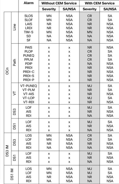

Starting with Cisco IOS XE 17.15.1, the Signal Failure (SF) and Signal Degrade (SD) Bit Error Rate (BER) alarms are raised when there is a signal failure or signal degradation occurs in the traffic.
-
The alarm severity for SF-BER, SD-BER alarm is critical for non-telcordia profile.
The alarm severity for SF-BER, SD-BER alarm is NA for Telcordia profile.
The SD-BER and SF-BER alarms are supported on the following interface modules:
-
48-Port T1 or E1 CEM interface module
-
48-Port T31 or E3 CEM interface module
Voltage
For normal operation, only one power feed (A900-PWR900-D2) is sufficient but an alarm is generated if only one power feed is present. You can suppress this alarm using the Voltage alarm profile configuration.
-
Voltage Out of Ranage
Note |
Voltage is applicable only to the chassis. |
Alarm Support for Loopback
Starting with Cisco IOS XE Amsterdam 17.3.1 release, alarm support is provided for loopback.
When the port, path, VT, or T1 is in the loopback mode, minor or NSA alarm is raised based on the loopback status.
Starting with Cisco IOS XE Cupertino 17.9.1 release, loopback syslogs are allowed in maintenance mode on 1-port OC481/ STM-16 or 4-port OC-12/OC-3 / STM-1/STM-4 + 12-Port T1/E1 + 4-Port T3/E3 CEM and 48-port T3/E3 CEM interface modules.
Telcordia Profile for Loopback Alarms
When the Telcordia is enabled on the chassis entity, you can view the loopback alarms based on the functioning of a service on that entity.
-
You can view the loopback alarms using the show facility condition status command, only when a service is configured on the controller.
-
Loopback alarm with network payload is not displayed using the show facility condition status command, as this loopback does not require a service to be configured on the path.
Default Alarm Profiles
The default alarm profiles are used when user-created alarm profiles are not configured. The default alarm profile contains the whole set of required alarms with severities as defined in the GR-253 standard with syslog enabled.
When the alarm profile of types such as chassis, card, or port is created, the alarm profile inherits configurations such as severity and syslog of the default profile. You can suppress the alarm with default severity and the alarm that is suppressed is not displayed under the show alarm-profile command.
You can also change the severity and syslog for a specific alarm, for example, SLOS alarm, and the severity and syslog remain intact for the remaining alarms set for the default profile.
How to Configure Alarm Profile
This section provides information about configuring alarm profile for chassis, interface, or port.
Creating Alarm Profile
While creating an alarm profile, note the following:
-
The alarm profile name should be a string of alpha numeric characters.
-
The alarm profile is associated with an alarm with controller types such as T1 or E1, T3 or E3, and SDH or SONET.
-
You can suppress syslog and provide a new severity for the alarm.
Starting with Cisco IOS XE Amsterdam 17.3.1, the alarm severity NR is included. You can set the alarm severity NR while creating alarm profile for chassis, interface, and port.
Note |
To ensure the logging of alarms, use the logging alarm [critical | major | minor | informational] for releases earlier to Cisco IOS XE Amsterdam 17.3.1. From Cisco IOS XE Amsterdam 17.3.1 onwards, use the logging alarm [critical | major | minor | informational | NR] command. |
Note |
You cannot provide the same profile name for chassis, interface, or port. |
Creating Alarm Profile for Chassis
To create the alarm profile for chassis, use the following commands:
router(config)#alarm-profile profile-name chassis
router(config-alarm-profile)#alarm {ds1 | ds3 | gig | sonet/sdh}
router(config-alarm-properties)#alarm-name suppress
router(config-alarm-properties)#alarm-name severity severity-level
router(config-alarm-properties)#ains
The command ains enables Auto In-Service (AINS) on the chassis.
Note |
When the alarm profile is attached to the chassis, all cards and ports on the chassis inherit the severity from the chassis profile. |
Note |
Ensure that you should not use Telcordia as the alarm profile name. |
Creating Alarm Profile for Interface Module
To create the alarm profile for interface module, use the following commands:
 router(config)#alarm-profile profile-name card
router(config-alarm-profile)#alarm {ds1 | ds3 | gig | sonet/sdh}
router(config-alarm-properties)#alarm-name suppress
router(config-alarm-properties)#alarm-name severity severity-level
router(config-alarm-properties)#ains
The command ains enables AINS on the card.
Note |
When the alarm profile is attached to a card, all ports on the card inherit the severity from the interface module profile. |
Note |
If a chassis profile is already attached and if you want to have a separate profile for an interface module, you can still create the interface module profile and attach it to that interface module. The interface module and all its ports inherit the properties of the interface module profile. |
Creating Alarm Profile for Port
To create the alarm profile for port, use the following commands:
 router(config)#alarm-profile profile-name port
router(config-alarm-profile)#alarm {ds1 | ds3 | gig | sonet/sdh}
router(config-alarm-properties)#alarm-name suppress
router(config-alarm-properties)#alarm-name severity severity-level
router(config-alarm-properties)#ains
The command ains enables AINS on the port.
Note |
When the alarm profile attached to a port, only the port inherits the severity from the port profile. |
Note |
If the chassis profile is already attached and if you want to have a separate profile for a port, you can still create a port profile and attach it to that port. The port inherits the properties of the port profile. |
The following example describes on how to create the alarm profile CHASSIS with severity critical for DS1 alarm:
router(config)#alarm-profile CHASSIS chassis
router(config-alarm-profile)#alarm ds1
router(config-alarm-properties)#DS1_LOS suppress
router(config-alarm-properties)#DS1_LOS severity critical
router(config-alarm-properties)# ains
The following example describes on how to create the alarm profile CARD with severity major for DS1 alarm:
router(config)#alarm-profile CARD card
router(config-alarm-profile)#alarm ds1
router(config-alarm-properties)#DS1_LOS suppress
router(config-alarm-properties)#DS1_LOS severity major
router(config-alarm-properties)# ains
The following example describes on how to create the alarm profile PORT with severity major for DS1 alarm:
 router(config)#alarm-profile PORT port
router(config-alarm-profile)#alarm ds1
router(config-alarm-properties)#DS1_LOS suppress
router(config-alarm-properties)#DS1_LOS severity major
router(config-alarm-properties)# ains
The following example describes on how to create the alarm profile CHASSIS with severity major for DS3 alarm:
router(config)#alarm-profile CHASSIS chassis
router(config-alarm-profile)#alarm ds3
router(config-alarm-properties)#DS3_LOS suppress
router(config-alarm-properties)#DS3_LOS severity major
The following example describes on how to create the alarm profile CARD with severity major for DS3 alarm:
To create the alarm profile CARD, use the following commands:
router(config)#alarm-profile CARD card
router(config-alarm-profile)#alarm ds3
router(config-alarm-properties)#DS3_LOS suppress
router(config-alarm-properties)#DS3_LOS severity major
The following example describes on how to create the alarm profile PORT with severity major for DS3 alarm:
router(config)#alarm-profile PORT port
router(config-alarm-profile)#alarm ds3
router(config-alarm-properties)#DS3_LOS suppress
router(config-alarm-properties)#DS3_LOS severity major
The following example describes on how to create the alarm profile CHASSIS with severity critical for SONET or SDH alarm:
router(config)#alarm-profile CHASSIS chassis
router(config-alarm-profile)#alarm sonet
router(config-alarm-properties)#SLOF suppress
router(config-alarm-properties)#SLOF severity critical
The following example describes on how to create the alarm profile CHASSIS with severity minor for SONET or SDH alarm:
router(config)#alarm-profile CHASSIS chassis
router(config-alarm-profile)#alarm sonet
router(config-alarm-properties)#SLOF suppress
router(config-alarm-properties)#SLOF severity minor
The following example describes on how to create the alarm profile CARD with severity critical for SONET or SDH alarm:
router(config)#alarm-profile CARD card
router(config-alarm-profile)#alarm sonet
router(config-alarm-properties)#SLOF suppress
router(config-alarm-properties)#SLOF severity critical
The following example describes on how to create the alarm profile PORT with severity critical for SONET or SDH alarm:
router(config)#alarm-profile PORT port
router(config-alarm-profile)#alarm sonet
router(config-alarm-properties)#SLOF suppress
router(config-alarm-properties)#SLOF severity critical
Attaching Alarm Profile to Entity
Once the alarm profile is created, attach the alarm profile to the appropriate entity. You can apply the alarm severity and other alarm functionalities only after attaching the alarm profile to the entity.
Attaching Alarm Profile to Chassis
To attach the alarm profile to chassis, use the following commands:
router>enable
router#configure terminal
router(config)#alarm-profile profile-name attach chassis
router(config)#end
Note |
When an alarm profile is attached to chassis, the profile is applicable to all the cards available on the chassis, but not to cards that are inserted after the profile is attached. To attach alarm profile to cards,reattach the alarm profile to the chassis. |
Attaching Telcordia Alarm Profile to Chassis
Starting with the Cisco IOS XE Amsterdam 17.3.1, you can attach a Telcordia profile to the chassis. The alarm severities Not Alarmed (NA) and Not Reported (NR) are included by default in the Telcordia profile. The alarm profile attached to chassis inherits the alarm severities of the Telcordia profile.
To attach the alarm profile based on Telcordia to chassis, use the following commands:
router>enable
router#configure terminal
router(config)#alarm-profile telcordia attach chassis
router(config)#end
Note |
Ensure that you use the complete alarm-profile telcordia attach chassis command while attaching the alarm profile based on Telcordia. |
Attaching Alarm Profile to Interface Module
To attach an alarm profile to the interface module, use the following commands:
router>enable
router#configure terminal
router(config)#alarm-profile profile-name attach card slot/bay
router(config)#end
Note |
The alarm profile cannot be attached to a slot when there is no card available in the slot. |
Attaching Alarm Profile to Port
Depending on the controller type, the alarm profile is attached to the port. The supported controller types are SONET, SDH, T1, T3, E1, and E3. Select the controller and the port, and then attach the profile to the port.
To attach the alarm profile to port, use the following commands:
router>enable
router#configure terminal
router(config)#controller {sonet | sdh | t1 | e1 | t3 | e3} slot/bay/port
router(config-controller)#attach profile profile-name
router(config-controller)#end
To attach the port profile to Ethernet interface, use the following commands:
router>enable
router#configure terminal
router(config)#interface gigabitethernet 0/7/0
router(config-controller)#  attach profile port
router(config-controller)#end
Note |
The following restrictions apply to the 8/16-port 1 Gigabit Ethernet (SFP/SFP) + 1-port 10 Gigabit Ethernet (SFP+) / 2-port 1 Gigabit Ethernet (CSFP) Interface Module:
|
The following example describes on how to attach the alarm profile CHASSIS:
router>enable
router#configure terminal
router(config)#alarm-profile CHASSIS attach chassis
router(config)#end
The following example describes on how to attach the alarm profile CARD:
router>enable
router#configure terminal
router(config)#alarm-profile CARD attach card slot/bay
router(config)#end
The following example describes on how to attach the alarm profile PORT on the SONET controller:
router>enable
router#configure terminal
router(config)#controller sonet  0/5/0
router(config-controller)#rate OC48
router(config-controller)#no ais-shut
router(config-controller)#attach profile PORT
router(config-controller)#end
Modifying Alarm Profile
You can modify the existing alarm profile associated with chassis, port, or interface. You can modify the alarm severity and suppress (or disable) the syslog facility. The alarm severity that you can modify are critical, major, minor, and informational.
Modifying Alarm Profile for Chassis
To modify the existing alarm configured for chassis, use the following commands:
router(config)#alarm-profile profile-name chassis
router(config-alarm-profile)#alarm sonet/sdh
router(config-alarm-properties)#SLOF suppress
router(config-alarm-properties)#SLOF severity major
Note |
You cannot modify the alarm profile based on Telcordia. |
Modifying Alarm Profile for Interface Module
To modify the existing alarm configured for card, use the following commands:
router(config)#alarm-profile profile-name card
router(config-alarm-profile)#alarm sonet/sdh
router(config-alarm-properties)#SLOF suppress
router(config-alarm-properties)#SLOF severity major
Modifying Alarm Profile for Port
To modify the existing alarm configured for port, use the following commands:
router(config)#alarm-profile profile-name port
router(config-alarm-profile)#alarm sonet/sdh
router(config-alarm-properties)#SLOF suppress
router(config-alarm-properties)#SLOF severity major
The following example describes how to modify the existing alarm severity for the alarm profile CHASSIS:
router(config)#alarm-profile CHASSIS chassis
router(config-alarm-profile)#alarm sonet/sdh
router(config-alarm-properties)#SLOF suppress
router(config-alarm-properties)#SLOF severity major
The following example describes how to modify the existing alarm severity for the alarm profile CARD:
router(config)#alarm-profile CARD card
router(config-alarm-profile)#alarm sonet/sdh
router(config-alarm-properties)#SLOF suppress
router(config-alarm-properties)#SLOF severity major
The following example describes how to modify the existing alarm severity for the alarm profile PORT:
router(config)#alarm-profile PORT port
router(config-alarm-profile)#alarm sonet/sdh
router(config-alarm-properties)#SLOF suppress
router(config-alarm-properties)#SLOF severity major
Detaching Alarm Profile
You can detach the existing alarm profile from chassis, interface, or port and attach a new profile. If a new alarm profile is not attached, then the default profile is attached.
Detaching Alarm Profile from Chassis
When the alarm profile associated with chassis is detached, the profile is removed from all the interfaces available in the chassis. The alarms configured for the profile have no effect on these interfaces even when alarm conditions occur.
To detach the alarm profile associated with chassis, use the following commands:
Router#configure terminal
Router(config)#no alarm-profile profile-name attach chassis
Router(config)#end
To detach the alarm profile based on Telcordia, use the following commands:
Router#configure terminal
Router(config)#no alarm-profile telcordia attach chassis
Router(config)#end
Detaching Alarm Profile from Interface Module
For the alarm profile associated with an interface module, when detached, the profile is removed from all the ports and the interfaces. While detaching alarm profile, specify the slot and subslot.
To detach the alarm profile associated with the card, use the following commands:
Router#configure terminal
Router(config)#no alarm-profile profile-name attach  CARD 0/9
Router(config)#end
Detaching Alarm Profile from Port
To detach an alarm profile associated with the port, you must access the specific controller and interface. The alarm profile is detached from specific interface for the controller.
To detach the alarm profile associated with a port, use the following commands:
Router#configure terminal
Router(config)#controller {DS1 | DS3 | gig | sonet/sdh} slot/bay/port
Router(config-controller)#no attach profile profile-name
Router(config-controller)#end
The following example describes how to detach the alarm profile CHASSIS associated with chassis:
Router#configure terminal
Router(config)#no alarm-profile CHA attach chassis
Router(config)#end
The following example describes how to detach the alarm profile CARD associated with chassis:
Router#configure terminal
Router(config)#no alarm-profile CARD attach card 0/9
Router(config)#end
The following example describes how to detach the alarm profile PORT associated with chassis:
Router#configure terminal
Router#controller sonet 0/9/16
Router(config-controller)#no attach profile PORT
Router(config-controller)#end
Deleting Alarm Profile
Note |
Before deleting the alarm profile, detach the profile from chassis, interface, or port. Alarm profiles cannot be deleted when profiles are attached to an entity. |
Deleting Alarm Profile for Chassis
To delete the alarm profile associated with the chassis, use the following command:
Router(config)no alarm-profile CHASSIS chassis
Note |
You cannot delete the alarm profile based on Telcordia. |
Deleting Alarm Profile for Interface Module
To delete the alarm profile associated with a card, use the following command:
Router(config)no alarm-profile CARD card
Deleting Alarm Profile for Port
To delete the alarm profile associated with a port, use the following command:
Router(config)no alarm-profile PORT port
Verifying Alarm Profile for T1 or E1 Alarms
Use the following commands to verity the alarm profile configuration:
-
show alarm-profile name—Displays the alarm profile configured for chassis.
-
show facility-alarm status—Displays the alarms status attached to a specific profile.
-
show controller—Displays the alarm profiles configured for a specific port.
-
show logging—Displays the alarms reporting in syslog.
To display the alarm profile configured for chassis, use the show alarm-profile name command:
Router# show alarm-profile name CHASSIS
Alarm profile CHASSIS:
  DS1:
  Alarm Name                           Severity   Syslog
  Receiver has loss of signal          CRITICAL   Enabled
  Receiver has loss of frame           INFO       Enabled
  Receiver has remote alarm            INFO       Enabled
To display the alarm status attached to a specfic profile, use the show facility-alarm status command:
Router# show facility-alarm status | inc 0/3/0
t1 0/3/0  Feb 01 2018 19:23:10  CRITICAL  Section Receiver has loss of signal  [1]
Verifying Alarm Profile for Severity Change for T1 or E1 Alarms
The following example verifies when the severity of the T1 or E1 alarms are modified for a Chassis profile. The alarm severity changes are verified using the show alarm-profile name command:
Create a CHASSIS alarm profile for the DS1 alarms:
Router(config)#alarm-profile CHASSIS chassis
Router(config-alarm-properties)#alarm ds1
Router(config-alarm-properties)#DS1_LOF severity critical
Router(config-alarm-properties)#DS1_LOF suppress
Router(config-alarm-properties)#alarm ds1
Router(config-alarm-properties)#DS1_RAI severity info
Router(config-alarm-properties)#DS1_RAI suppress
Verify the CHASSIS alarm profile using the show alarm-profile name command:
Router#show alarm-profile name CHASSIS
Alarm profile CHASSIS:
  Alarm Name                                          Severity       Syslog
  Receiver has loss of signal                         CRITICAL       Enabled
  Receiver has remote alarm                           MINOR          Enabled
Attach the CHASSIS alarm profile to chassis:
router>enable
router#configure terminal
router(config)#alarm-profile CHASSIS attach chassis
router(config)#end
Modify the severity of the CHASSIS alarm profile for the DS1 alarms:
Router(config)#alarm-profile CHASSIS chassis
Router(config-alarm-properties)#alarm ds1
Router(config-alarm-properties)#DS1_LOF severity major
Router(config-alarm-properties)#DS1_LOF suppress
Router(config-alarm-properties)#alarm ds1
Router(config-alarm-properties)#DS1_RAI severity info
Router(config-alarm-properties)#DS1_RAI suppress
Verify the CHASSIS alarm profile with modified severity:
Router#show alarm-profile name CHASSIS
Alarm profile CHASSIS:
DS1:
  Alarm Name                                          Severity       Syslog
  Receiver has loss of signal                         MAJOR          Enabled
  Receiver has remote alarm                           INFO           Enabled
Verifying Alarm Profile for T3 or E3 Alarms
Use the following commands to verity the alarm profile configuration:
-
show alarm-profile name—Displays the alarm profile configured for chassis.
-
show facility-alarm status—Displays the alarms status attached to a specific profile.
-
show controller—Displays the alarm profiles configured for a specific port.
-
show logging—Displays the alarms reporting in syslog.
To display the alarm profile configured for chassis, use the show alarm-profile name command:
Router# show alarm-profile name CHASSIS
Alarm profile CHASSIS:
  DS3:
  Alarm Name                           Severity   Syslog
  Receiver has loss of signal          MAJOR      Enabled
  DS1 Alarm Indication Signal          MINOR      Enabled
  DS1 Loss Of Frame                    INFO       Enabled
  DS1 Remote Alarm Indication          INFO       Enabled
To display the alarm status attached to a specfic profile, use the show facility-alarm status command:
Router# show facility-alarm status | inc 0/4/40
T3 0/4/40  Feb 01 2018 19:23:10  MAJOR  Section Receiver has loss of signal [1]
Verifying Alarm Profile for Severity Change for T3 or E3 Alarms
The following example verifies when the severity of the T3 or E3 alarms are modified for a Chassis profile. The alarm severity changes are verified using the show alarm-profile name command:
Create a CHASSIS alarm profile for the DS1 alarms:
Router(config)#alarm-profile CHASSIS chassis
router(config-alarm-profile)#alarm ds3
router(config-alarm-properties)#DS3_LOS suppress
router(config-alarm-properties)#DS3_LOS severity major
router(config-alarm-properties)#MCPRP_DS3_DS1_LOS suppress
router(config-alarm-properties)#MCPRP_DS3_DS1_LOS severity minor
Verify the CHASSIS alarm profile using the show alarm-profile name command:
Router#show alarm-profile name CHASSIS
Alarm profile CHASSIS:
  Alarm Name                                          Severity       Syslog
  Receiver has loss of signal                         MAJOR          Enabled
  DS1 Loss Of Signal                                  MINOR          Enabled
Attach the CHASSIS alarm profile to chassis:
router>enable
router#configure terminal
router(config)#alarm-profile CHASSIS attach chassis
router(config)#end
Modify the severity of the CHASSIS alarm profile for the DS1 alarms:
router(config)#alarm-profile CHASSIS chassis
router(config-alarm-profile)#alarm ds3
router(config-alarm-properties)#DS3_LOS suppress
router(config-alarm-properties)#DS3_LOS severity minor
router(config-alarm-properties)#MCPRP_DS3_DS1_LOS suppress
router(config-alarm-properties)#MCPRP_DS3_DS1_LOS severity minor
Verify the CHASSIS alarm profile with modified severity:
Router#show alarm-profile name CHASSIS
Alarm profile CHASSIS:
DS1:
  Alarm Name                                          Severity       Syslog
  Receiver has loss of signal                         MINOR          Enabled
  DS1 Loss Of Signal                                  MINOR          Enabled
Verifying Alarm Profile for SONET or SDH
Use the following commands to verify the alarm profile configuration:
-
show alarm-profile name—Displays the alarm profile configured for chassis.
-
show facility-alarm status—Displays the status of the alarms attached to a specific profile.
-
show facility-ains transceiver—Displays the transceiver status.
-
show controller/interface—Displays the operational alarm profile attached to the controller or interface.
-
show logging—Displays the alarms reported in the syslog.
-
show facility-condition status—Displays the secondary alarms on the controller, alarms when the port is in AUTO-IN-SERVICE state and the loopback alarm
To display the alarm profile configured for the chassis, use the show alarm-profile name command:
Router# show alarm-profile name CHASSIS
Alarm profile CHASSIS:
 SONET/SDH:
  Alarm Name                           Severity   Syslog
  Section Loss of Frame Failure        CRITICAL   Enabled
  Line Alarm Indication Signal         INFO       Enabled
  Line Remote Failure Indication       INFO       Enabled
  Path Alarm Indication Signal         INFO       Enabled
  Path Remote Failure Indication       INFO       Enabled
  Path Loss of Pointer                 INFO       Enabled
 DS1:
  Alarm Name                           Severity   Syslog
  Receiver has loss of signal          CRITICAL   Enabled
  Receiver has loss of frame           INFO       Enabled
  Receiver has remote alarm            INFO       Enabled
 DS3:
  Alarm Name                           Severity   Syslog
  Receiver has loss of signal          MAJOR      Enabled
  DS1 Alarm Indication Signal          MINOR      Enabled
  DS1 Loss Of Frame                    INFO       Enabled
  DS1 Remote Alarm Indication          INFO       Enabled
To display the alarm status attached to a specfic profile, use the show facility-alarm status command:
Router# show facility-alarm status | include 0/4/1
SONET 0/4/1  Feb 01 2018 19:23:10  INFO  Section Loss of Frame Failure [1]
To display the alarm status and the service affecting state for each source with Telcordia enabled, use the show facility-alarm status command:
Router#show facility-alarm status
Source                     Time                   Severity      Service Affecting  Syslog String                  Description [Index]
------                     ------                 --------      -----------------  -------------                  -------------------
Power Supply Bay 0         Feb 10 2020 18:57:25   CRITICAL      SA                  PSU_MISSING                    Power Supply/FAN Module Missing [0]
Fan Tray/Ext. ALARM:       Feb 10 2020 19:06:23   MAJOR         NSA                 Fan Failure                    Fan Tray/Fan 7 Failure [14]
GigabitEthernet0           Feb 10 2020 18:57:25   NA            NSA                 ETHERNET_PORT_ADMIN_DOWN       Physical Port Administrative State Down [2]
GigabitEthernet0/1/1       Feb 10 2020 18:57:58   CRITICAL      SA                  ETHERNET_PORT_LINK_DOWN        Physical Port Link Down [1]
xcvr container 0/1/2       Feb 10 2020 18:57:52   CRITICAL      SA                  XCVR_MISSING_LINK_DOWN         Transceiver Missing - Link Down [1]
xcvr container 0/1/3       Feb 10 2020 18:57:52   CRITICAL      SA                  XCVR_MISSING_LINK_DOWN         Transceiver Missing - Link Down [1]
xcvr container 0/1/4       Feb 10 2020 18:57:52   CRITICAL      SA                  XCVR_MISSING_LINK_DOWN         Transceiver Missing - Link Down [1]
xcvr container 0/1/5       Feb 10 2020 18:57:52   CRITICAL      SA                  XCVR_MISSING_LINK_DOWN         Transceiver Missing - Link Down [1]
xcvr container 0/1/6       Feb 10 2020 18:57:52   CRITICAL      SA                  XCVR_MISSING_LINK_DOWN         Transceiver Missing - Link Down [1]
xcvr container 0/1/7       Feb 10 2020 18:57:52   CRITICAL      SA                  XCVR_MISSING_LINK_DOWN         Transceiver Missing - Link Down [1]
SONET 0/2/16               Feb 10 2020 19:11:16   MINOR         NSA                 SLOS                           Section Loss of Signal Failure [0]
SONET 0/2/16               Feb 10 2020 19:11:16   NR            NSA                 SONET_LINK_DOWN                Physical Port Link Down [59]
IM subslot 0/3             Feb 10 2020 18:57:38   MAJOR         NSA                                                Disabled [2]
IM subslot 0/4             Feb 10 2020 18:57:38   MAJOR         NSA                                                Disabled [2]
IM subslot 0/5             Feb 10 2020 18:57:38   MAJOR         NSA                                                Disabled [2]
System Totals  Critical: 8  Major: 4  Minor: 1 NA: 1
Note |
The SA column is displayed only when the profile based on Telcordia is attached. |
Router#show facility-alarm status | inc 0/4/1
SONET 0/4/1  Feb 01 2018 19:23:10  INFO  Section Loss of Frame Failure [1]
To display the operational or attached alarm profile, use the show interfaces command:
Router#show interfaces gigabitEthernet 0/7/0
GigabitEthernet0/7/0 is down, line protocol is down
Alarm-profile: chassis_ains
  Hardware is A900-IMA8CS1Z-M, address is 5006.ab62.3a36 (bia 5006.ab62.3a36)
  MTU 1500 bytes, BW 1000000 Kbit/sec, DLY 10 usec,
     reliability 255/255, txload 1/255, rxload 1/255
  Encapsulation ARPA, loopback not set
  Keepalive set (10 sec)
  Full Duplex, 1000Mbps, link type is force-up, media type is SX
  output flow-control is unsupported, input flow-control is on
  ARP type: ARPA, ARP Timeout 04:00:00
  Last input never, output never, output hang never
  Last clearing of "show interface" counters never
  Input queue: 0/375/0/0 (size/max/drops/flushes); Total output drops: 0
  Queueing strategy: fifo
  Output queue: 0/40 (size/max)
  5 minute input rate 0 bits/sec, 0 packets/sec
  5 minute output rate 0 bits/sec, 0 packets/sec
     0 packets input, 0 bytes, 0 no buffer
     Received 0 broadcasts (0 IP multicasts)
     0 runts, 0 giants, 0 throttles
     0 input errors, 0 CRC, 0 frame, 0 overrun, 0 ignored
0 watchdog, 0 multicast, 0 pause inputRouter#show interfaces GigabitEthernet 0/1/0
GigabitEthernet0/1/0 is up, line protocol is up
Sec-admin-state: in-service, Soak-time: NA,
soak-Time-left: NA, AINS-state: IS-NR
Hardware is A900-IMA8S1Z, address is f078.1685.3f12 (bia f078.1685.3f12)
MTU 1500 bytes, BW 1000000 Kbit/sec, DLY 10 usec,
reliability 255/255, txload 1/255, rxload 1/255
Encapsulation ARPA, loopback not set
Keepalive set (10 sec)
Full Duplex, 1000Mbps, link type is auto, media type is SX
output flow-control is unsupported, input flow-control is on
ARP type: ARPA, ARP Timeout 04:00:00
Last input never, output never, output hang never
Last clearing of "show interface" counters 00:00:37
Input queue: 0/375/0/0 (size/max/drops/flushes); Total output drops: 0
Queueing strategy: fifo
Output queue: 0/40 (size/max)
5 minute input rate 0 bits/sec, 0 packets/sec
5 minute output rate 0 bits/sec, 0 packets/sec
0 packets input, 0 bytes, 0 no buffer
Received 0 broadcasts (0 IP multicasts)
0 runts, 0 giants, 0 throttles
0 input errors, 0 CRC, 0 frame, 0 overrun, 0 ignored
0 watchdog, 0 multicast, 0 pause input
0 packets output, 0 bytes, 0 underruns
0 output errors, 0 collisions, 0 interface resets
0 unknown protocol drops
0 babbles, 0 late collision, 0 deferred
0 lost carrier, 0 no carrier, 0 pause output
0 output buffer failures, 0 output buffers swapped outTo display the alarm status configured for chassis, use the show facility-alarm status command:
Router#show facility-alarm status
System Totals  Critical: 25  Major: 5  Minor: 0
Source           Severity      Syslog String                  Description [Index]

subslot 0/12             CRITICAL                                     Active Card Removed OIR Alarm [0]
Power Supply Bay 3       CRITICAL      PSU_MISSING                    Power Supply/FAN Module Missing [0]
module R1                MAJOR                                        Unknown state [0]
SONET 0/4/1              CRITICAL      SLOS                           Section Loss of Signal Failure [0]
SONET 0/4/1              CRITICAL      SONET_LINK_DOWN                Physical Port Link Down [59]
xcvr container 0/4/5     INFO          XCVR_MISSING                   Transceiver Missing [0]
xcvr container 0/4/6     INFO          XCVR_MISSING                   Transceiver Missing [0]
xcvr container 0/4/7     INFO          XCVR_MISSING                   Transceiver Missing [0]
xcvr container 0/7/1     CRITICAL      XCVR_MISSING_LINK_DOWN         Transceiver Missing - Link Down [1]
xcvr container 0/7/3     CRITICAL      XCVR_MISSING_LINK_DOWN         Transceiver Missing - Link Down [1]
xcvr container 0/7/4     CRITICAL      XCVR_MISSING_LINK_DOWN         Transceiver Missing - Link Down [1]
xcvr container 0/7/5     CRITICAL      XCVR_MISSING_LINK_DOWN         Transceiver Missing - Link Down [1]
xcvr container 0/7/6     CRITICAL      XCVR_MISSING_LINK_DOWN         Transceiver Missing - Link Down [1]
xcvr container 0/7/7     CRITICAL      XCVR_MISSING_LINK_DOWN         Transceiver Missing - Link Down [1]
xcvr container 0/7/8     CRITICAL      XCVR_MISSING_LINK_DOWN         Transceiver Missing - Link Down [1]
xcvr container 0/7/9     CRITICAL      XCVR_MISSING_LINK_DOWN         Transceiver Missing - Link Down [1]
xcvr container 0/7/11    CRITICAL      XCVR_MISSING_LINK_DOWN         Transceiver Missing - Link Down [1]
xcvr container 0/7/13    CRITICAL      XCVR_MISSING_LINK_DOWN         Transceiver Missing - Link Down [1]
xcvr container 0/7/14    CRITICAL      XCVR_MISSING_LINK_DOWN         Transceiver Missing - Link Down [1]
xcvr container 0/7/15    CRITICAL      XCVR_MISSING_LINK_DOWN         Transceiver Missing - Link Down [1]
xcvr container 0/8/18    INFO          XCVR_MISSING                   Transceiver Missing [0]
xcvr container 0/8/19    INFO          XCVR_MISSING                   Transceiver Missing [0]
xcvr container 0/14/2    INFO          XCVR_MISSING                   Transceiver Missing [0]
xcvr container 0/14/4    INFO          XCVR_MISSING                   Transceiver Missing [0]
Verifying Alarm Profile for Severity Change for SONET or SDH Alarms
Create a port alarm profile for the SONET or SDH alarms:
Router(config)#alarm-profile PORT port
Router(config-alarm-properties)#alarm sonet/sdh
Router(config-alarm-properties)#lais severity critical
Router(config-alarm-properties)#puneq severity major
Router(config-alarm-properties)#pais severity major
Router(config-alarm-properties)#end
Verify the alarm profile using the show alarm-profile command:
Router#show alarm-profile PORT
Alarm profile PORT:
SONET/SDH:
  Alarm Name                                         Severity   Syslog
  Line Alarm Indication Signal                        CRITICAL   Enabled
  Path Alarm Indication Signal                        MINOR      Enabled
  Path Payload Unequipped                             MAJOR      Disabled
  Lower Order Path Alarm Indication Signal            MINOR      Disabled
Attach port alarm profile to port:
 Router>enable
Router#configure terminal
Router(config)#controller sonet 0/3/3
Router(config-controller)#attach profile PORT
Router(config-controller)#end
Modify the severity of the port alarm profile for the SONET or SDH alarms:
Router(config)#alarm-profile PORT port
Router(config-alarm-properties)#alarm sonet/sdh
Router(config-alarm-properties)#PAIS suppress
Router(config-alarm-properties)#LAIS severity info
Router(config-alarm-properties)# end
Verify the port alarm profile with modified severity:
Router#show alarm-profile PORT
Alarm profile PORT:
SONET/SDH:
  Alarm Name                                         Severity     Syslog
  Line Alarm Indication Signal                       INFO         Enabled
  Path Alarm Indication Signal                       MINOR        Enabled
  Path Payload Unequipped                            MAJOR        Disabled
  Lower Order Path Alarm Indication Signal           MINOR        Enabled
Alarm Profile Use Cases for T1 or E1 Alarms
Use Case 1
The following example explains default alarm profile having DS1_AIS alarm with severity as MINOR and syslog is enabled, and when the alarm is configured as suppressed with default severity, the alarm is not displayed under the show alarm-profile name command.
Use the following steps to suppress the default alarm profile:
-
Create a chassis profile, for example, chassis and verity that the DS1_AIS alarm is listed under the show alarm-profile name chassis command.
-
Set the alarm DS1_AIS as suppressed.
The alarm DS1_AIS is not displayed under the show alarm-profile name chassis command.
Create chassis profile
Router#configure terminal
Router(config)#alarm-profile chassis chassis
Router(config-alarm-profile)#end
Router#show alarm-profile name chassis
Alarm profile chassis:
  DS1:
  Alarm Name                                                                                        Severity   Syslog
  Transmitter is sending AIS                                                                        MINOR       Enabled
  Receiver has loss of signal                                                                       CRITICAL    Enabled
  Receiver has loss of frame                                                                        INFO        Enabled
  Receiver has remote alarm INFO                                                                    INFO        Enabled
Set the alarm DS1_AIS as suppressed
Router(config)#alarm-profile chassis chassis
Router(config-alarm-profile)#alarm ds1
Router(config-alarm-properties)#DS1_AIS suppress
Router(config-alarm-properties)#end
Note that the DS1_AIS alarm is not displayed under the show alarm-profile name chassis command.
Router#show alarm-profile name chassis
Alarm profile chassis:
  DS1:
  Alarm Name                                                                                        Severity   Syslog
  Receiver has loss of signal                                                                       CRITICAL    Enabled
  Receiver has loss of frame                                                                        INFO        Enabled
  Receiver has remote alarm                                                                         INFO        Enabled
Use Case 2
The following example displays default profile having DS1_AIS alarm with severity as MINOR and syslog enabled, and when the alarm is configured as suppressed with severity set to INFO, the alarm is displayed under the show alarm-profile name command.
Use the following steps to change the DS1_AIS alarm severity:
-
Create a chassis profile, for example, chassis.
-
Set the alarm DS1_AIS as suppressed and alarm DS1_AIS severity to INFO.
The alarm DS1_AIS is displayed under the show alarm-profile name chassis command.
Create chassis profile
Router#configure terminal
Router(config)#alarm-profile chassis chassis
Router(config-alarm-profile)#end
Set the alarm DS1_AIS as suppressed and severity to INFO
Router(config)#alarm-profile chassis chassis
Router(config-alarm-profile)#alarm ds1
Router(config-alarm-properties)#DS1_AIS suppress
Router(config-alarm-properties)#DS1_AIS severity INFO
Router(config-alarm-properties)#end
Note that the DS1_AIS alarm is displayed under the show alarm-profile name chassis command.
Router#show alarm-profile name chassis
Alarm profile chassis:
  DS1:
 Alarm Name                                                                                        Severity   Syslog
 Transmitter is sending AIS                                                                        MINOR       Enabled
 Receiver has loss of signal                                                                       CRITICAL    Enabled
 Receiver has loss of frame                                                                        INFO        Enabled
 Receiver has remote alarm                                                                         INFO        Enabled
Use Case 3
The following example displays default profile having DS1_LOF and DS1_RAI alarms with severities as CRITICAL and MINOR respectively. Using the chassis profile, you can set the DS1_LOF alarm severity to INFO and verify using the show alarm-profile name command. The show output displays the DS1_LOF as INFO and DS1_RAI as MINOR.
Use the following steps to change the DS1_LOF alarm severity:
-
Create a chassis profile, for example, chassis.
-
Set the alarm DS1_LOF severity to INFO.
The alarm DS1_LOF is displayed under the show alarm-profile name chassis command.
Create a chassis profile
Router#configure terminal
Router(config)#alarm-profile chassis chassis
Router(config-alarm-profile)#end
Set the alarm DS1_LOF severity to INFO
Router(config)#alarm-profile chassis chassis
Router(config-alarm-profile)#alarm t1
Router(config-alarm-properties)#DS1_LOF severity INFO
Router(config-alarm-properties)#end
Note that the DS1_LOF alarm is displayed under the show alarm-profile name chassis command.
Router#show alarm-profile name chassis
Alarm profile chassis:
 T1:
  Alarm Name                                                                                        Severity   Syslog
 Transmitter is sending AIS                                                                        MINOR       Enabled
 Receiver has loss of signal                                                                       CRITICAL    Enabled
 Receiver has loss of frame                                                                        INFO        Enabled
 Receiver has remote alarm                                                                         MINOR        Enabled
Use Case 4
The following example displays default profile having DS1_LOF and DS1_RAI alarms with severities as CRITICAL and MINOR respectively. Using the card profile, you can set the DS1_LOF alarm severity to MAJOR and verify using the show alarm-profile name command. The show output displays the DS1_LOF as MAJOR and DS1_RAI as MINOR.
Use the following steps to change the DS1_LOF alam severity:
-
Create a card profile, for example, card.
-
Set the alarm DS1_LOF severity to MAJOR.
The alarm DS1_LOF with severity MAJOR is displayed under the show alarm-profile name command.
Create a card profile and set the alarm DS1_LOF severity to MAJOR
Router#configure terminal
Router(config)#alarm-profile card card
Router(config-alarm-profile)#alarm ds1
Router(config-alarm-properties)#DS1_LOF severity MAJOR
Router(config-alarm-properties)#end
Note that the DS1_LOF with severity MAJOR and DS1_RAI with severity MINOR are displayed under the show alarm-profile name command.
Router#show alarm-profile name card
Alarm profile card:
 DS1:
Alarm Name                                                                                         Severity   Syslog
 Transmitter is sending AIS                                                                        MINOR       Enabled
 Receiver has loss of signal                                                                       CRITICAL    Enabled
 Receiver has loss of frame                                                                        MAJOR        Enabled
 Receiver has remote alarm                                                                         MINOR        Enabled
Use Case 5
The following example displays default profile having DS1_LOF and DS1_RAI alarms with severities as CRITICAL and MINOR respectively. Using the port profile, you can set the DS1_LOF alarm severity to MAJOR and DS1_RAI alarm severity to INFO. Verify using the show alarm-profile name command. The show output displays the DS1_LOF as MAJOR and DS1_RAI as INFO.
Use the following steps to change the DS1_LOF and DS1_RAI alarm severities:
-
Create a port profile, for example, port.
-
Set the alarm severities DS1_LOF to MAJOR and DS1_RAI to INFO.
The alarm DS1_LOF with severity MAJOR and DS1_RAI with severity INFO are displayed under the show alarm-profile name command.
Create a port profile and set the alarm severities of DS1_LOF to MAJOR and DS1_RAI to INFO
Router#configure terminal
Router(config)#alarm-profile port port
Router(config-alarm-profile)#alarm ds1
Router(config-alarm-properties)#DS1_LOF severity MAJOR
Router(config-alarm-properties)#DS1_RAI severity MINOR
Router(config-alarm-properties)#end
Note that the DS1_LOF with severity MAJOR and DS1_RAI with severity INFO are displayed under the show alarm-profile name command.
Router#show alarm-profile name port
Alarm profile port:
 DS1:
Alarm Name                                                                                         Severity   Syslog
 Transmitter is sending AIS                                                                        MINOR       Enabled
 Receiver has loss of signal                                                                       CRITICAL    Enabled
 Receiver has loss of frame                                                                        MAJOR        Enabled
 Receiver has remote alarm                                                                         INFO        Enabled
Alarm Profile Use Cases for T3 or E3 Alarms
Use Case 1
The following example explains default alarm profile having DS3_DS1_AIS alarm with severity as MINOR and syslog is enabled, and when the alarm is configured as suppressed with default severity, the alarm is not displayed under the show alarm-profile name command.
Use the following steps to suppress the default alarm profile:
-
Create a chassis profile, for example, chassis and verity that the DS3_DS1_AIS alarm is listed under the show alarm-profile name chassis command.
-
Set the alarm DS3_DS1_AIS as suppressed.
The alarm DS3_DS1_AIS is not displayed under the show alarm-profile name chassis command.
Create chassis profile
Router#configure terminal
Router(config)#alarm-profile chassis chassis
Router(config-alarm-profile)#end
Router#show alarm-profile name chassis
Alarm profile chassis:
  DS1:
  Alarm Name                                                                                        Severity   Syslog
  DS1 Alarm Indication Signal                                                                       MINOR       Enabled
  Transmitter is sending AIS                                                                        MINOR       Enabled
  Receiver has loss of signal                                                                       CRITICAL    Enabled
  Receiver has loss of frame                                                                        INFO        Enabled
  Receiver has remote alarm                                                                         INFO        Enabled
Set the alarm DS3_DS1_AIS as suppressed
Router(config)#alarm-profile chassis chassis
Router(config-alarm-profile)#alarm ds3
Router(config-alarm-properties)#DS3_DS1_AIS suppress
Router(config-alarm-properties)#end
Note that the DS3_DS1_AIS alarm is not displayed under the show alarm-profile name chassis command.
Router#show alarm-profile name chassis
Alarm profile chassis:
  DS1:
  Alarm Name                                                                                        Severity   Syslog
  Receiver has loss of signal                                                                       CRITICAL    Enabled
  Receiver has loss of frame                                                                        INFO        Enabled
  Receiver has remote alarm                                                                         INFO        Enabled
Use Case 2
The following example displays default profile having DS3_DS1_AIS alarm with severity as MINOR and syslog enabled, and when the alarm is configured as suppressed with severity set to INFO, the alarm is displayed under the show alarm-profile name command.
Use the following steps to change the DS3_DS1_AIS alarm severity:
-
Create a chassis profile, for example, chassis.
-
Set the alarm DS3_DS1_AIS as suppressed and alarm DS3_DS1_AIS severity to INFO.
The alarm DS3_DS1_AIS is displayed under the show alarm-profile name chassis command.
Create chassis profile
Router#configure terminal
Router(config)#alarm-profile chassis chassis
Router(config-alarm-profile)#end
Set the alarm DS3_DS1_AIS as suppressed and severity to INFO
Router(config)#alarm-profile chassis chassis
Router(config-alarm-profile)#alarm ds3
Router(config-alarm-properties)#DS3_DS1_AIS suppress
Router(config-alarm-properties)#DS3_DS1_AIS severity INFO
Router(config-alarm-properties)#end
Note that the DS3_DS1_AIS alarm is displayed under the show alarm-profile name chassis command.
Router#show alarm-profile name chassis
Alarm profile chassis:
DS1:
  Alarm Name                                                                                        Severity   Syslog
  DS1 Alarm Indication Signal                                                                       INFO       Enabled
  Transmitter is sending AIS                                                                        MINOR       Enabled
  Receiver has loss of signal                                                                       CRITICAL    Enabled
  Receiver has loss of frame                                                                        INFO        Enabled
  Receiver has remote alarm                                                                         INFO        Enabled
Use Case 3
The following example displays default profile having DS3_AIS and DS3_LOS alarms with severities as MINOR and MAJOR respectively. Using the chassis profile, you can set the DS3_LOS alarm severity to INFO and verify using the show alarm-profile name command. The show output displays theDS3_LOS as INFO and DS3_AIS as MINOR.
Use the following steps to change the DS3_LOS alarm severity:
-
Create a chassis profile, for example, chassis.
-
Set the alarm DS3_LOS severity to INFO.
The alarm DS3_LOS is displayed under the show alarm-profile name chassis command.
Create a chassis profile
Router#configure terminal
Router(config)#alarm-profile chassis chassis
Router(config-alarm-profile)#end
Set the alarm DS3_LOS severity to INFO
Router(config)#alarm-profile chassis chassis
Router(config-alarm-profile)#alarm ds3
Router(config-alarm-properties)#DS3_LOS severity INFO
Router(config-alarm-properties)#end
Note that the DS3_LOS alarm is displayed under the show alarm-profile name chassis command.
Router#show alarm-profile name chassis
Alarm profile chassis:
 T1:
  Alarm Name                                                                                        Severity   Syslog
 Transmitter is sending AIS                                                                        MINOR       Enabled
 Receiver has loss of signal                                                                       INFO        Enabled
 Receiver has loss of frame                                                                        INFO        Enabled
 Receiver has remote alarm                                                                         MINOR        Enabled
Use Case 4
The following example displays default profile having DS3_AIS and DS3_LOS alarms with severities as MINOR and MAJOR respectively. Using the card profile, you can set the DS3_LOS alarm severity to MINOR and verify using the show alarm-profile name command. The show output displays the DS3_AIS and DS3_LOS severities as MINOR.
Use the following steps to change the DS3_LOS alarm severity:
-
Create a card profile, for example, card.
-
Set the alarm DS3_LOS severity to MINOR.
The alarm DS3_LOS with severity MINOR is displayed under the show alarm-profile name command.
Create a card profile and set the alarm DS3_LOS severity to MINOR
Router#configure terminal
Router(config)#alarm-profile card card
Router(config-alarm-profile)#alarm ds3
Router(config-alarm-properties)#DS3_LOS severity MINOR
Router(config-alarm-properties)#end
Note that the DS3_LOS and DS3_AIS with severities MINOR are displayed under the show alarm-profile name card command.
Router#show alarm-profile name card
Alarm profile card:
 DS1:
Alarm Name                                                                                         Severity   ``Syslog
 Transmitter is sending AIS                                                                        MINOR       `Enabled
 Receiver has loss of signal                                                                       MINOR    ````Enabled
 Receiver has loss of frame                                                                        MAJOR        Enabled
 Receiver has remote alarm                                                                         MINOR        Enabled
Use Case 5
The following example displays default profile having DS3_AIS and DS3_LOS alarms with severities as MINOR and MAJOR respectively. Using the port profile, you can set the DS3_LOS alarm severity to MINOR and DS3_AIS alarm severity to INFO. Verify using the show alarm-profile name command. The show output displays the DS3_AIS as INFO and DS3_LOS as MINOR.
Use the following steps to change the DS3_AIS and DS3_LOS alarm severities:
-
Create a port profile, for example, port.
-
Set the DS3_LOS alarm severity to MINOR and DS3_AIS alarm severity to INFO.
The alarm DS3_AIS as INFO and DS3_LOS as MINOR are displayed under the show alarm-profile name command.
Create a port profile and set the alarm severities
Router#configure terminal
Router(config)#alarm-profile port port
Router(config-alarm-profile)#alarm ds3
Router(config-alarm-properties)#DS3_AIS severity INFO
Router(config-alarm-properties)#DS3_LOS severity MINOR
Router(config-alarm-properties)#end
Note that the DS3_AIS as INFO and DS3_LOS as MINOR are displayed under the show alarm-profile name command.
Router#show alarm-profile name port
Alarm profile port:
 DS1:
Alarm Name                                                                                         Severity   Syslog
 Transmitter is sending AIS                                                                        INFO       Enabled
 Receiver has loss of signal                                                                       MINOR    Enabled
 Receiver has loss of frame                                                                        MAJOR        Enabled
 Receiver has remote alarm                                                                         INFO        Enabled
Alarm Profile Use Cases for SONET or SDH Alarms
Use Case 1
In the following use case the default alarm profile has a Line Alarm Indication Signal (LAIS) alarm with severity as MINOR and syslog is enabled. When the LAIS alarm is re-configured as suppressed with default severity, the alarm is not displayed under the show alarm-profile name command.
-
Create a chassis profile, for example, chassis and verify that the LAIS alarm is listed under the show alarm-profile name chassis command.
-
Set the alarm LAIS as suppressed.
The alarm LAIS is not displayed under the show alarm-profile name chassis command.
Create chassis profile
Router#configure terminal
Router(config)#alarm-profile chassis chassis
Router(config-alarm-profile)#end
Router#show alarm-profile name chassis
Alarm profile chassis:
  SONET/SDH:
  Alarm Name                                                                                        Severity   Syslog
  Section Loss of Signal Failure                                                                    CRITICAL   Enabled
  Section Loss of Frame Failure                                                                     CRITICAL   Enabled
  Section Out of Frame Alignment                                                                    CRITICAL   Enabled
  Section J0 mismatch                                                                               CRITICAL   Enabled
  Section Bit Interleaved Parity                                                                    CRITICAL   Enabled
  Line Alarm Indication Signal                                                                      MINOR      Enabled
  Line Remote Failure Indication
Set the alarm LAIS as suppressed
Router(config)#alarm-profile chassis chassis
Router(config-alarm-profile)#alarm sonet/sdh
Router(config-alarm-properties)#LAIS suppress
Router(config-alarm-properties)#end
Use the show alarm-profile name chassis command to display the configured alarm profile.
Router#show alarm-profile name chassis
Alarm profile chassis:
 DS1:
  Alarm Name                                                                                        Severity   Syslog
  Section Loss of Signal Failure                                                                    CRITICAL   Enabled
  Section Loss of Frame Failure                                                                     CRITICAL   Enabled
  Section Out of Frame Alignment                                                                    CRITICAL   Enabled
  Section J0 mismatch                                                                               CRITICAL   Enabled
  Section Bit Interleaved Parity                                                                    CRITICAL   Enabled
  Line Remote Failure Indication                                                                    MINOR      Enabled
Note |
The LAIS alarm is not displayed under the show alarm-profile name chassis command. |
Use Case 2
In this use case, the default profile has the LAIS alarm with severity as MINOR and syslog enabled. When the alarm is re-configured as suppressed with severity set to INFO, the alarm is displayed under the show alarm-profile name command.:
Use the following steps to change the LAIS alarm severity:
-
Create a chassis profile, for example, chassis.
-
Set the alarm LAIS as suppressed and alarm LAIS severity to INFO.
The alarm LAIS is displayed under the show alarm-profile name chassis command.
Create chassis profile
Router#configure terminal
Router(config)#alarm-profile chassis chassis
Router(config-alarm-profile)#end
Set the alarm LAIS as suppressed and severity to INFO
Router(config)#alarm-profile chassis chassis
Router(config-alarm-profile)#alarm sonet/sdh
Router(config-alarm-properties)#LAIS suppress
Router(config-alarm-properties)#LAIS severity INFO
Router(config-alarm-properties)#end
Router#show alarm-profile name chassis
Alarm profile chassis:
  SONET/SDH:
Alarm Name                                     Severity     Syslog
Section Loss of Signal Failure                 CRITICAL     Enabled
Section Loss of Frame Failure                  CRITICAL     Enabled
Section Out of Frame Alignment                 CRITICAL     Enabled
Section J0 mismatch                            CRITICAL     Enabled
Section Bit Interleaved Parity                 CRITICAL     Enabled
Line Alarm Indication Signal                INFO         Disabled
Line Remote Failure Indication                 MINOR        Enabled
Note that the LAIS alarm is displayed under the show alarm-profile name chassis command.
Use Case 3
In this use case, the default profile has Section Loss of Signal (SLOS) and Path Alarm Indication Signal (PAIS) alarms with severity as CRITICAL. Using the chassis profile, severity of the PAIS alarm is set to INFO, which is then verified using the show alarm-profile name command. The show output displays the SLOS as CRITICAL and PAIS as INFO.
Use the following steps to change the PAIS alarm severity:
-
Create a chassis profile, for example, chassis.
-
Set the alarm PAIS severity to INFO.
Create a chassis profile
Router#configure terminal
Router(config)#alarm-profile chassis chassis
Router(config-alarm-profile)#end
Set the alarm PAIS severity to INFO
Router(config)#alarm-profile chassis chassis
Router(config-alarm-profile)#alarm sonet/sdh
Router(config-alarm-properties)#PAIS severity INFO
Router(config-alarm-properties)#end
Router#show alarm-profile name chassis
Alarm profile chassis:
  SONET/SDH:
Alarm Name                                     Severity     Syslog
Section Loss of Signal Failure              CRITICAL     Enabled
Section Loss of Frame Failure                  CRITICAL     Enabled
Section Out of Frame Alignment                 CRITICAL     Enabled
Section J0 mismatch                            CRITICAL     Enabled
Section Bit Interleaved Parity                 CRITICAL     Enabled
Line Alarm Indication Signal                   INFO         Disabled
Line Remote Failure Indication                 MINOR        Enabled
Path Alarm Indication Signal                INFO         Enabled
Note that the PAIS alarm is displayed under the show alarm-profile name chassis command.
Use Case 4
In this use case, the default profile has SLOS and PAIS alarms with severity as CRITICAL. Using the card profile, set the PAIS alarm severity to MAJOR and verify the severity using the show alarm-profile name command. The show output displays the SLOS as MAJOR and PAIS as CRITICAL.
Use the following steps to change the PAIS alarm severity:
-
Create a card profile, for example, card.
-
Set the alarm SLOS severity to MAJOR.
Create a card profile and set the alarm SLOS severity to MAJOR
Router#configure terminal
Router(config)#alarm-profile card card
Router(config-alarm-profile)#alarm sonet/sdh
Router(config-alarm-properties)#SLOS severity MAJOR
Router(config-alarm-properties)#end
Router#show alarm-profile name card
Alarm profile card:
 SONET/SDH:
  Alarm Name                                                   Severity   Syslog
  Section Loss of Signal Failure                            MAJOR      Enabled
  Section Loss of Frame Failure                                CRITICAL   Enabled
  Section Out of Frame Alignment                               CRITICAL   Enabled
  Section J0 mismatch                                          CRITICAL   Enabled
  Section Bit Interleaved Parity                               CRITICAL   Enabled
  Line Alarm Indication Signal                                 INFO       Disabled
  Path Alarm Indication Signal                              CRITICAL   Enabled
Note |
The new severity levels for SLOS are displayed under the show alarm-profile name card command. |
Use Case 5
In this use case, the default profile has the DS1_LOS and DS1_PAIS alarms with severity as CRITICAL. Using the port profile, set the DS1_LOS alarm severity to MAJOR and DS1_AIS alarm severity to MINOR. Verify the new severity levels of the alarms by using the show alarm-profile name command.
Use the following steps to change the DS1_LOS and DS1_AIS alarm severities:
-
Create a port profile, for example, port.
-
Set the alarm severities DS1_LOS to MAJOR and DS1_AIS to MINOR.
Create a port profile and set the alarm severities of DS1_LOS to MAJOR and DS1_AIS to MINOR
Router#configure terminal
Router(config)#alarm-profile port port
Router(config-alarm-profile)#alarm sonet/sdh
Router(config-alarm-properties)#DS1_LOS severity MAJOR
Router(config-alarm-properties)#DS1_AIS severity MINOR
Router(config-alarm-properties)#end
Router#show alarm-profile name port
Alarm profile port:
SONET/DSH:
 Alarm Name Severity Syslog
DS1 Loss Of Signa MAJOR Enabled
Section Loss of Frame Failure CRITICAL Enabled
Line Alarm Indication Signal CRITICAL Disabled
Line Remote Failure Indication MINOR Enabled
DS1 Alarm Indication Signal MINOR Enabled
Path Remote Failure Indication
Note |
The new severity levels for DS1_LOS and DS1_AIS are displayed under the show alarm-profile name port command. |
 Feedback