Configuring IP Multicast Over Unidirectional Links

Internet routing protocol assumes that links in a network are bidirectional, and neighborships are formed on bidirectional links that are directly connected. However, in certain scenarios such as satellite links, the links in the network are unidirectional. For routing protocols to work over unidirectional links, you must perform certain configurations. See the following feature document that explains how to configure IP Multicast over unidirectional link (UDL) on the IOS XE platform.

Information About IP Multicast over UDL

Unicast and multicast routing protocols assume that links in a network are bidirectional, and forward data on interfaces from which they have received the routing control information. However, some network links are unidirectional, and usually, in a unidirectional network, the physical send-only interface is on the upstream router (for example, a satellite). The physical receive-only interface is on the downstream router (for example, a ship). In this case, a method of communication that allows the routing protocol to operate in a unidirectional environment is necessary.

Configuring Multicast over UDL helps you achieve control information in a unidirectional environment. You must configure a Unidirectional Link Routing (UDLR) tunnel as a unidirectional generic routing encapsulation (GRE) tunnel and map this tunnel to a one-way satellite link. By doing so, the UDLR tunnel mechanism enables the associated unicast and multicast routing protocols to treat the UDL as a bidirectional link. Before getting into the configuration, you must understand what is UDLR.

What is UDLR?

In unicast routing, when a router receives an update message on an interface for a prefix, it forwards the data to the destinations that match that prefix. Similarly, in multicast routing, when a router receives a join message for a multicast group on an interface, it forwards copies of the data that is destined for that group out from that same interface. Based on these principles, unicast and multicast routing protocols are not supported over UDLs without the use of UDLR. UDLR enables the operation of routing protocols over UDLs without changing the routing protocols themselves. UDLR also enables a router to emulate the behaviour of a bidirectional link for IP operations over the UDLs through a tunnel.

UDLR Tunnel

The UDLR tunnel is the back channel of a unidirectional high-capacity link which transparently emulates a single, bidirectional link for unicast and multicast traffic. A UDLR tunnel enables IP and its associated unicast and multicast routing protocols to treat the UDL as being logically bidirectional. A packet that is destined on a receive-only interface is picked up by the UDLR tunnel mechanism and sent to an upstream router using a generic routing encapsulation (GRE) tunnel. The control traffic thus flows in the opposite direction of the user data flow. When the upstream router receives this packet, the UDLR tunnel makes it appear that the packet was received on a send-only interface on the UDL.

The purpose of the GRE tunnel is to move control packets from a downstream node to an upstream node. This one-way tunnel is mapped to a one-way interface that goes in the opposite direction. The mapping is performed at the link layer so that the one-way interface appears bidirectional. When the upstream node receives packets over the tunnel, it causes the upper-layer protocols to act as if the packets were received on the send-capable UDL.

A UDLR tunnel supports the following functionalities:

  • Address Resolution Protocol (ARP) and Next Hop Resolution Protocol (NHRP) over a UDL

  • Emulation of bidirectional links for all the IP traffic

  • Support for IP GRE multipoint at a receive-only tunnel


Note


A UDL router can have many routing peers (for example, routers interconnected via a broadcast satellite link). As with bidirectional links, ensure that the number of peer routers is relatively small, to limit the volume of routing updates that are processed.


Multicast Over UDL For Cisco IOS XE

The Multicast over UDL functionality is supported for PIM starting from the IOS XE Amsterdam 17.3.1 release. See the following sample topology that specifies the events that happen sequentially:

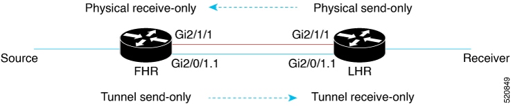
  • The PIM router receives a PIM join from the downstream PIM neighbor.

  • The PIM router connects to the FHR router through the UDLR tunnel.

  • The PIM router forwards the PIM join towards the FHR router through the physical interface.

  • After the PIM join is received, the FHR router forwards the corresponding multicast traffic to the PIM router through the UDLR tunnel interface. The traffic is encapsulated so that the traffic is not blocked.

In an encap-helper (encapsulated) tunnel on a physical interface, all the (*/S, G) MROUTE entries having the physical interface as the outgoing interface (OIF), use the tunnel interface as the OIF. All the multicast traffic destined to the physical interface flows through the configured tunnel with the encapsulation.

A new flag is propagated and is first introduced to MROUTE. This flag is set against an entry, provided the entry has at least one physical interface as the OIF on which the encap-helper is configured. Consequently, a new flag is introduced to MRIB, which is set against the entry that corresponds to the MROUTE entry. Similarly, a new flag is introduced to MFIB that corresponds to the MRIB entry. The flag is then visible to the platform which punts the multicast traffic only for those (*/S, G) entries based on the status of the flag. The IOS process then switches the packets and sends out these GRE-encapsulated packets.


Note


When you remove or disable the encap-helper tunnel configuration on a physical interface, all the (*/S, G) MROUTE entries having the tunnel interface as the OIF use the physical interface as the OIF. The encap-helper feature is removed on the interface and the default behavior is enabled.


Prerquisites for Multicast Over UDL

  • Configure IP multicast in your network. For more information, see the Configuring Basic IP Multicast section.

  • Ensure that the physical interface and the tunnel interface are on the same mvrf.

Restrictions for Multicast Over UDL

  • This functionality is supported only for IPv4 addresses and not IPv6 addresses.

  • Bidirectional PIM is not supported.

  • The encap-helper command is visible only on the physical interfaces, in the supported platforms.

  • If the tunnel interface is not up, or if the interface is on a different mvrf compared to the physical interface, the encap-helper configuration does not work.

  • This functionality is supported only in the PIM sparse mode.

How to Configure Multicast Over UDL

To configure the IP multicast over UDL functionality, execute the Router(config-if)# [no] ip pim sparse-mode encap-helper tunnel <tunnel-number> command.


Note


You can configure the UDLR tunnel only in the pim sparse-mode.


Router (config)# interface Tunnel1001
vrf forwarding VRF1
no ip address
ip pim sparse-mode
tunnel source GigabitEthernet2/0/1.1
tunnel destination 3.3.5.3
tunnel key 7354
tunnel udlr send-only GigabitEthernet2/1/1
tunnel udlr address-resolution
tunnel vrf VRF1
end
LMA1#sh runn int  GigabitEthernet2/1/1
Building configuration...

Current configuration : 177 bytes
!
interface GigabitEthernet2/1/1
vrf forwarding VRF1
ip address 12.12.2.1 255.255.255.0
ip pim sparse-mode encap-helper Tunnel1001
ip ospf 101 area 0
negotiation auto
end

When you execute the udlr send-only command, it associates the tunnel send-only interface with the receive-only port.

When you execute the encap-helper command, the encap-helper tunnel is configured on a physical interface. All the (*/S, G) MROUTE entries with the physical interface as the OIF use the tunnel interface as the OIF. All the multicast traffic destined to the physical interface flows through the configured tunnel interface with the encapsulation.


Note


When the tunnel interface goes down, the tunnel interfaces in the OIF list are removed.


Verifying Multicast Over UDL Configuration

Verify whether the configuration is successful by executing the following show commands:

Router# show ip mroute vrf VRF1
IP Multicast Routing Table
Flags: D - Dense, S - Sparse, B - Bidir Group, s - SSM Group, C - Connected,
L - Local, P - Pruned, R - RP-bit set, F - Register flag,
T - SPT-bit set, J - Join SPT, M - MSDP created entry, E - Extranet,
X - Proxy Join Timer Running, A - Candidate for MSDP Advertisement,
U - URD, I - Received Source Specific Host Report,
Z - Multicast Tunnel, z - MDT-data group sender,
Y - Joined MDT-data group, y - Sending to MDT-data group,
G - Received BGP C-Mroute, g - Sent BGP C-Mroute,
N - Received BGP Shared-Tree Prune, n - BGP C-Mroute suppressed,
Q - Received BGP S-A Route, q - Sent BGP S-A Route,
V - RD & Vector, v - Vector, p - PIM Joins on route,
x - VxLAN group, c - PFP-SA cache created entry,
* - determined by Assert, # - iif-starg configured on rpf intf,
e - encap-helper tunnel flag
Outgoing interface flags: H - Hardware switched, A - Assert winner, p - PIM Join
Timers: Uptime/Expires
Interface state: Interface, Next-Hop or VCD, State/Mode
(*, 239.1.1.1), 00:28:39/stopped, RP 4.4.3.4, flags: SPF
  Incoming interface: GigabitEthernet2/1/1, RPF nbr 12.12.2.2
  Outgoing interface list: Null
(100.100.3.2, 239.1.1.1), 00:28:39/00:02:58, flags: FTe, eh_tun_count :1
Incoming interface: GigabitEthernet2/0/4.2, RPF nbr 0.0.0.0
Outgoing interface list:
Tunnel1001, Forward/Sparse, 00:24:59/00:03:21
(*, 224.0.1.40), 02:10:54/00:02:08, RP 4.4.3.4, flags: SJCL
Incoming interface: GigabitEthernet2/1/1, RPF nbr 12.12.2.2
 Outgoing interface list:
 Loopback1, Forward/Sparse, 02:10:52/00:02:08
Router(config-if)# show ip mrib vrf VRF1 route
IP Multicast Routing Information Base
Entry flags: L - Domain-Local Source, E - External Source to the Domain,
C - Directly-Connected Check, S - Signal, IA - Inherit Accept, D - Drop
ET - Data Rate Exceeds Threshold,K - Keepalive,DDE - Data Driven Event
ME - MoFRR ECMP Flow based, MNE - MoFRR Non-ECMP Flow based,
MP - Primary MoFRR Non-ECMP Flow based entry,
e  - Encap helper tunnel flag
Interface flags: F - Forward, A - Accept, IC - Internal Copy,
NS - Negate Signal, DP - Don't Preserve, SP - Signal Present,
II - Internal Interest, ID - Internal Disinterest, LI - Local Interest,
LD - Local Disinterest, MD - mCAC Denied, MI - mLDP Interest
 A2 - MoFRR ECMP Backup Accept
(*,224.0.0.0/4) Flags: C
(*,224.0.1.40) RPF nbr: 12.12.2.2 Flags: C
 GigabitEthernet2/1/1 Flags: A NS
 Loopback1 Flags: F IC NS
(*,239.1.1.1) RPF nbr: 12.12.2.2 Flags: C
 GigabitEthernet2/1/1 Flags: A
(100.100.3.2,239.1.1.1) RPF nbr: 0.0.0.0 Flags: e
 GigabitEthernet2/0/4.2 Flags: A
 Tunnel1001 Flags: F NS
Router# show ip mfib vrf VRF1
Entry Flags:  C - Directly Connected, S - Signal, IA - Inherit A flag,
             ET - Data Rate Exceeds Threshold, K - Keepalive
             DDE - Data Driven Event, HW - Hardware Installed
             ME - MoFRR ECMP entry, MNE - MoFRR Non-ECMP entry, MP - MFIB
             MoFRR Primary, RP - MRIB MoFRR Primary, P - MoFRR Primary
             MS  - MoFRR  Entry in Sync, MC - MoFRR entry in MoFRR Client,
             e   - Encap helper tunnel flag.
I/O Item Flags: IC - Internal Copy, NP - Not platform switched,
             NS - Negate Signalling, SP - Signal Present,
             A - Accept, F - Forward, RA - MRIB Accept, RF - MRIB Forward,
             MA - MFIB Accept, A2 - Accept backup,
             RA2 - MRIB Accept backup, MA2 - MFIB Accept backup
 
Forwarding Counts: Pkt Count/Pkts per second/Avg Pkt Size/Kbits per second
Other counts:      Total/RPF failed/Other drops
I/O Item Counts:   HW Pkt Count/FS Pkt Count/PS Pkt Count   Egress Rate in pps
VRF VRF1
(*,224.0.0.0/4) Flags: C HW
   SW Forwarding: 0/0/0/0, Other: 0/0/0
   HW Forwarding:   0/0/0/0, Other: 19/19/0
(*,224.0.1.40) Flags: C HW
   SW Forwarding: 0/0/0/0, Other: 0/0/0
   HW Forwarding:   0/0/0/0, Other: 0/0/0
   GigabitEthernet2/1/1 Flags: A NS
   Loopback1 Flags: F IC NS
     Pkts: 0/0/0    Rate: 0 pps
(*,239.1.1.1) Flags: C HW
   SW Forwarding: 0/0/0/0, Other: 0/0/0
   HW Forwarding:   0/0/0/0, Other: 0/0/0
   GigabitEthernet2/1/1 Flags: A
(100.100.3.2,239.1.1.1) Flags: HW e
   SW Forwarding: 1623356/997/46/358, Other: 1/0/1
   HW Forwarding:   101680/0/63/0, Other: 33853/1/33852
   GigabitEthernet2/0/4.2 Flags: A
   Tunnel1001 Flags: F NS
     Pkts: 0/0/1539215    Rate: 0 pps

The encap tunnel prefixed with ā€˜eā€™ indicates the entry of the new flag for MROUTE, MFIB. The highlighted portions also indicate the successful configuration of the tunnel interface and the SW Forwarding counters.