Hardware Components
The hardware components that enable Routed Optical Networking are:
-
High Density Routers
-
High Capacity Pluggable Optical Modules
-
Optical Line Systems
Cisco 8000 Series Routers
The Cisco 8000 series routers utilize Cisco's Silicon One ASIC to deliver full routing functionality at higher capacities and a lower environmental footprint than any other routing silicon available. The Silicon One architecture supports large forwarding tables, deep buffers, flexible packet operations, and enhanced programmability.
The 8000 series are highly scalable, deep-bufferred, 100G/400G/800G optimized routers. They are also available with additional on-chip High Bandwidth Memory (HBM) to support additional resource scale. The Cisco 8000 series routers support both ZR and ZR+ modules.
Cisco 8200 Series Routers
The Cisco 8200 Series uses a single Cisco Silicon One ASIC to deliver full routing functionality. The Cisco 8200 Series is designed for relatively high-buffer and high-scale use cases. These fixed port, high-density routers provide 10.8 Tbps of network bandwidth with dramatically lower power consumption than contemporary 10 Tbps systems.
This table details the specifications of the routers.
| Router | Capacity | Form factor | 400G QSFP-DD Ports | 100G QSFP28 Ports |
|---|---|---|---|---|
| Cisco 8201 | 10.8 Tbps | 1 RU | 24 | 12 |
| Cisco 8202 | 10.8 Tbps | 2 RU | 12 | 60 |
| Cisco 8201-32FH | 12.8 Tbps | 1 RU |
32 |
– |
|
Cisco 8202-32FH-M |
12.8 Tbps | 2 RU |
32 |
– |
|
Cisco 8201-24H8FH |
5.6 Tbps | 1 RU |
8 |
24 |
Cisco 8800 Series Routers
The Cisco 8800 Series delivers density and efficiency with the extensive scale, buffering, and all feature capabilities that are common to Cisco 8000 Series routers. The 8800 series routers provide up to approximately 260 Tbps through 648 400 GbE ports. The 8800 series includes four chassis to meet a broad set of network and facility requirements.
This table details the specifications of the routers.
| Router | Capacity | Form factor | 400G QSFP-DD Ports |
|---|---|---|---|
| Cisco 8804 | Up to 57.6 Tbps | 4-slot/10 RU |
Up to 144 |
| Cisco 8808 | Up to 115.2 Tbps | 8-slot/16 RU |
Up to 288 |
| Cisco 8812 | Up to 172.8 Tbps | 12-slot/21 RU |
Up to 432 |
| Cisco 8818 | Up to 259.2 Tbps | 18-slot/33 RU |
Up to 648 |
Cisco 8800 Series Line Cards
The Cisco 8800 Series modular platform supports 400 GbE line cards.
This table details the specifications of the line cards.
| Line Cards | Bandwidth | 400G QSFP-DD Ports |
|---|---|---|
| 8800-LC-36FH | 14.4 Tbps | 36 |
| 88-LC0-36FH-M | 14.4 Tbps | 36 |
| 88-LC0-36FH | 14.4 Tbps | 36 |
For information on ZR/ZR+ port support, see 400G ZR/ZR+ Transceivers.
For more information about Cisco 8000 Series Routers, see the Cisco 8000 Series Routers Data Sheet.
Cisco Network Convergence System 5500 Series
The Network Convergence System (NCS) 5500 platform offers high port density, high-performance forwarding, low jitter, and low power consumption.
Cisco NCS-55A2 Series Fixed Port Routers
NCS-55A2-MOD-S is a fixed port, high density, 2-rack unit form-factor router. It supports 24 SFP/SFP+ ports capable of supporting Gigabit Ethernet or 10-Gigabit Ethernet, and 16 SFP/SFP+/SFP28 ports capable of supporting Gigabit Ethernet, 10-Gigabit Ethernet, or 25-Gigabit Ethernet. The router also supports up to 2 Modular Port Adapters (MPA).
This table details the specifications of the routers.
| Router | Capacity | Form factor | Nx100G QSFP-DD Ports on MPA-2D4H | 100G QSFP28 Ports on MPA-4H |
|---|---|---|---|---|
| NCS-55A2-MOD-S | 900Gbps | 2 RU | 8 | 8 |
For more information about Cisco NCS-55A2 Series Fixed Port Routers, see the Cisco Network Convergence System 5700 Series: NCS-55A2 Fixed Chassis Data Sheet.
Cisco NCS-57B1 Series Fixed Port Routers
The NCS-57B1-6D24-SYS and NCS-57B1-5DSE-SYS combine 4.8 Terabits of 400GE/100GE optimized forwarding capacity, QSFP-DD optics, deep packet buffering, full line-rate MACsec, Class C 1588 Precision Time Protocol (PTP), and Synchronous Ethernet (SyncE) in a power-efficient, 1-rack-unit package.
This table details the specifications of the routers.
| Router | Capacity | Form factor | 400G QSFP-DD Ports | 100G QSFP-DD Ports |
|---|---|---|---|---|
| NCS-57B1-6D24-SYS | Up to 4.8 Tbps | 1 RU | 6 | 24 |
| NCS-57B1-5DSE-SYS | Up to 4.4 Tbps | 1 RU | 5 | 24 |
For more information about Cisco NCS-57B1 Series Fixed Port Routers, see the Cisco Network Convergence System 5700 Series: NCS-57B1 Fixed Chassis Data Sheet.
Cisco NCS-57C1 Series Fixed Port Routers
NCS-57C1-48Q6D-S is a fixed chassis that combines low port densities of 1GE/10GE/25GE with higher port densities of 50GE/100GE/400GE and QSFP-DD optics, deep packet buffering, MACsec, Class C 1588 Precision Time Protocol (PTP), and Synchronous Ethernet (SyncE) in a power-efficient, 1-rack-unit package.
This table details the specifications of the routers.
| Router | Capacity | Form factor | 400G QSFP-DD Ports | 100G QSFP28 Ports |
|---|---|---|---|---|
| NCS-57C1-48Q6-SYS | Up to 2.4 Tbps | 1 RU |
6 four 400G and two Nx100G ports |
- |
For more information about Cisco NCS-57C1 Series Fixed Port Routers, see the Cisco Network Convergence System 5700 Series: NCS-57C1 Fixed Chassis Data Sheet.
Cisco NCS-57C3 Series Fixed Port Routers
The Cisco Network Convergence System 57C3 Series Routers are designed for cost-effective delivery of next-generation networking services. These routers are high-capacity and low-power-consuming devices available in a 3-rack-unit compact form factor. The chassis along with the Modular Port Adapters (MPAs) provide options of using different types of interfaces ranging from 1GE to 400GE along with industry-leading MACSec encryption and Class C Timing support. These devices also provide Control Plane redundancy, which enables high availability and reliability.
The Cisco NCS 57C3 Series Routers are well equipped for a range of applications such as Carrier Ethernet Aggregation, Subscriber Services, Business Ethernet, Mobile Edge, Campus, Peering, and Core roles. Powered by the industry-leading Cisco IOS® XR Software, the NCS 57C3 supports a rich and comprehensive set of features like QoS, IP/MPLS, Segment Routing, SRv6, and Ethernet VPN (EVPN).
This table details the specifications of the routers.
| Router | Capacity | Form factor | 400G QSFP-DD Ports on MPA-2D4H | 100G QSFP28 Ports on Base Unit |
|---|---|---|---|---|
| NCS-57C3-MOD-S | Up to 2.4 Tbps | 3 RU |
Slot 1 - 4 Nx100G ports, Slot 2 and 3 - two 400G ports or four Nx100G ports |
8 |
| NCS-57C3-MOD-SE | Up to 2.4 Tbps | 3 RU | 4 |
For more information about Cisco NCS-57C1 Series Fixed Port Routers, see the Cisco Network Convergence System 5700 Series: NCS-57C3 Fixed Chassis Data Sheet.
Cisco NCS 5500 Modular Chassis
The Cisco NCS 5500 modular chassis series is available in three system sizes: NCS 5504, NCS 5508, NCS 5516. All NCS systems are highly reliable and resilient platforms. They support a wide range of line card options. NCS 5500 modular router line cards and fabric modules directly attach to each other with connecting pins. In contrast, most traditional modular platform designs require a midplane.
This table details the specifications of the routers.
| Platform | Capacity | Form factor | 400G QSFP-DD Ports | 100G QSFP28 Ports |
| NCS 5504 | Up to 14.4 Tbps | 4-Slot / 7 RU | Up to 96 | Up to 144 |
| NCS 5508 | Up to 76.8 Tbps | 8-Slot / 13 RU | Up to 192 | Up to 288 |
| NCS 5516 | Up to 153.6 Tbps | 16-Slot / 21 RU | Up to 384 | Up to 576 |
For more information about Cisco Network Convergence System 5500 Series Modular Chassis, see the Cisco Network Convergence System 5500 Series Modular Chassis Data Sheet.
NCS 5700 Series Line Cards
NCS 5700 series line cards are 400G line cards for the NCS 5500 Series modular chassis. NCS 5700 series line cards consists of two versions of 400GE optimized line cards: the base version and the scale version. The two 400GE optimized line cards in the NCS5700 series are NC57-24DD and NC57-18DD-SE.
The Cisco NCS 5700 Series 100G optimized baseline card, NC57-36H6D-S is a combo line card with 4.8-Tbps throughput. NC57-36H6D-S provides a mix of 100GE, 200GE, and 400GE ports. NC57-36H6D-S line card provides flexible port configuration and can be used as 36x100GE or 24x100GE + 12x200GE(2x100GE) or 24x100GE + 6x400GE ports.
For information on ZR/ZR+ port support, see 400G ZR/ZR+ Transceivers.
For more information about Cisco Network Convergence System 5700 Series 400GE, see the Cisco Network Convergence System 5700 Series: 400GE and 100GE Line Cards Data Sheet.
NCS 5700 Series Modular Port Adapters
The Cisco Network Convergence System 5700 Series is designed to efficiently scale between data centers and large enterprises, web, and service provider WAN and aggregation networks. Equipping the chassis and the line cards with various interfaces is crucial to cater to a plethora of use cases and services. The Modular Port Adapters provide the much-needed flexibility and capability to the chassis and the line cards. They provide ports with bandwidth up to 400GE and pluggable form-factors like QSFP-DD.
NC57-MPA-2D4H-S MPA
NC57-MPA-2D4H-S is a 4-port 800GE modular port adapter (NC57-MPA-2D4H-S) that supports QSFP28 and QSFP-DD optical transceivers. All 4 ports support QSFP28-100GE transceivers. Ports 0 and 2 (even-numbered ports) support two QDD-400G transceivers at the same time. This configuration is supported in both the MPA slots of the NCS-55A2-MOD-HD-S, NC55-55A2-MOD-SE-S, NCS-55A2-MOD-S, or NCS-55A2-MOD-HX-S chassis. Port 0 supports only one QDD-400G transceiver in Nx100G modes in both the MPA slots of the NCS-55A2-MOD-HD-S, NC55-55A2-MOD-SE-S, NCS-55A2-MOD-S, or NCS-55A2-MOD-HX-S chassis.
NC55-OIP-02 MPA
NC55-OIP-02 is an 8-port modular port adapter that supports SFP+ optical transceivers. This MPA is supported in the NC55A2-MOD-S and NC57C3-MOD-SYS routers. This modular port adapter supports the following port modes:
-
Ethernet - 1GE, and 10GE
-
Fiber channel (FC) - 1GFC, 2GFC, 4GFC, 8GFC, 16GFC, 32GFC
-
Optical Transport Network (OTN) – OTU2, and OTU2e
-
SONET/SDH - OC-48/STM-16, OC-192/STM-64
NC55-OIP-02 MPA is used to support Private Line Emulation.
For more information about Cisco Network Convergence System 5700 Series Modular Port Adapters, see the Cisco Network Convergence System 5700 Series: Modular Port Adapters Data Sheet.
Cisco ASR 9000 Series Aggregation Services Routers
The Cisco ASR 9000 Series Aggregation Services Routers (ASR 9000 Series) represent an exciting new paradigm in edge and core routing, with exceptional scalability, carrier-class reliability, environmentally conscious design, incredible flexibility, and an attractive price-to-performance benchmark. The Cisco ASR 9000 Series has a wide product portfolio, ranging from the Cisco ASR 9001 (2 RU) to the Cisco ASR 9922 (44 RU), with each system that is designed to provide true carrier-class reliability using the Cisco IOS XR operating system, comprehensive system redundancy, and a full complement of network resiliency schemes. Finally, the Cisco ASR 9000 Series is designed to simplify and enhance the operational and deployment aspects of service-delivery networks.
The Cisco ASR 9000 Series offers advanced switching capacity, optimized power consumption and cooling, high-availability design, and a modular operating system to significantly lower the Total Cost of Ownership (TCO) for service providers.
This table details the specifications of the routers.
| Router | Capacity | Form Factor | 400G QSFP-DD Ports |
|---|---|---|---|
| ASR 9006 | Up to 16 Tbps | 10 RU | Up to 20 |
| ASR 9010 | Up to 32 Tbps | 21 RU | Up to 32 |
| ASR 9904 | Up to 16 Tbps | 6 RU | Up to 8 |
| ASR 9906 | Up to 32 Tbps | 14 RU | Up to 16 |
| ASR 9910 | Up to 64 Tbps | 21 RU | Up to 32 |
| ASR 9912 | Up to 80 Tbps | 30 RU | Up to 40 |
| ASR 9922 | Up to 160 Tbps | 44 RU | Up to 80 |
For more information on Cisco ASR 9000 Series Aggregation Services Routers, see Cisco ASR 9000 Series Aggregation Services Routers Data Sheet.
Cisco ASR 9902 Compact High-Performance Router
The Cisco ASR 9902 Router is a compact, high-performance router that delivers up to 800 Gbps of nonblocking, full-duplex capacity in a Two-Rack-Unit (2RU) form factor. Based on the same Cisco IOS® XR software image as the other routers in the Cisco ASR 9000 Series, the Cisco ASR 9902 Router delivers the features and services found on the ASR 9000 Series platforms, allowing customers to standardize on the same Cisco IOS XR operating system. Multiple port rates are supported by ASR 9902: 100/40 Gigabit Ethernet, 25-Gigabit Ethernet, and 10-Gigabit Ethernet, providing customers the flexibility to mix and match interface types on the same chassis and offering operators the readiness for mass-scale networking.
This table details the specifications of the router.
| Router | Capacity | Form Factor | 100G QSFP-DD Ports |
|---|---|---|---|
| ASR 9902 | Up to 800 Gbps | 2 RU | Up to 2 |
For more information on Cisco ASR 9902 Compact High-Performance Router, see Cisco ASR 9902 Compact High-Performance Router Data Sheet.
Cisco ASR 9903 Compact High-Performance Router
The Cisco ASR 9903 Router is a compact router that supports two redundant Route Processors (RP), two integrated switch fabrics, four AC or DC power supply modules, and four fans in redundant configuration. The router consists of the fixed board, with 16 integrated QSFP28-based 100GE ports, 20 integrated SFP+-based ports, and an optional Port Expansion Card (PEC), which you can insert into the dedicated slot on demand.
The ASR 9903 fixed board supports maximum 1.6T data bandwidth. The Cisco A9903-20HG-PEC offers 20 physical ports with maximum 2T data bandwidth capacity. Five of the 20 physical ports are 400GE/200GE/100GE multirate QSFP-DD/QSFP28-based ports, which you can individually migrate to 400GE using licenses. The other 15 ports are 100GE QSFP28-based ports.
This table details the specifications of the router.
| Router | Capacity | Form Factor | 400G QSFP-DD Ports |
|---|---|---|---|
| ASR 9903 | Up to 7.2 Tbps | 3 RU | Up to 5 |
For more information on Cisco ASR 9903 Compact High-Performance Router, see Cisco ASR 9903 Compact High-Performance Router Data Sheet.
Cisco ASR 9000 Series Line Cards
The Cisco ASR 9000 Series routers support 400G line cards.
ASR 9000 Series 5th Generation High-Density Multi-Rate Line Cards
The ASR 9000 Series 5th Generation High-Density Multi-Rate Line Cards are fully compatible with the following routers:
-
Cisco ASR 9006
-
Cisco ASR 9010
-
Cisco ASR 9904
-
Cisco ASR 9906
-
Cisco ASR 9910
-
Cisco ASR 9912
-
Cisco ASR 9922
This table details the specifications of the line cards.
| Line Card | Bandwidth | 400G QSFP-DD Ports |
|---|---|---|
| A9K-20HG-FLEX-SE | 2 Tbps | 5 |
| A9K-20HG-FLEX-TR | 2 Tbps | 5 |
| A9K-8HG-FLEX-SE | 800 Gbps | 2 |
| A9K-8HG-FLEX-TR | 800 Gbps | 2 |
For more information on Cisco ASR 9000 Series 5th Generation High-Density Multi-Rate Line Cards, see Cisco ASR 9000 Series 5th Generation High-Density Multi-Rate Line Cards: 2 Terabit and 0.8 Terabit Cards Data Sheet.
ASR 9900 Series 5th Generation 10-Port 400-Gigabit Ethernet Line Cards
The ASR 9900 Series 5th Generation 10-Port 400-Gigabit Ethernet Line Cards are fully compatible with the following routers:
-
Cisco ASR 9904
-
Cisco ASR 9906
-
Cisco ASR 9910
-
Cisco ASR 9912
-
Cisco ASR 9922
This table details the specifications of the line cards.
| Line Card | Bandwidth | 400G QSFP-DD Ports |
|---|---|---|
| A99-10X400GE-X-SE | 4 Tbps | 10 |
| A99-10X400GE-X-TR | 4 Tbps | 10 |
For information on ZR/ZR+ port support, see Table 1.
For more information on Cisco ASR 9900 Series 5th Generation 10-Port 400-Gigabit Ethernet Line Card, see Cisco ASR 9900 Series 5th Generation 10-Port 400 Gigabit Ethernet Line Card Data Sheet.
Cisco Network Convergence System 540 Series Routers
Cisco Network Convergence System (NCS) 540 Series is a converged access platform that is designed to cost-effectively deliver services and applications. The NCS 540 is temperature-hardened, low power consumption, and small form factor suitable for indoor or outdoor use.
Cisco Network Convergence System 540 Large Density Routers
The Cisco Network Convergence System (NCS) 540 large density router is a 1-RU platform that supports QSFP56-DD ports and offers you a 400G coherent optics transport solution. The NCS 540 large density platform enhances the existing NCS 540 portfolio by offering high throughput and flexible port interfaces ranging from 1G up to 400G.
Cisco NCS 540 large density routers are suitable for both outdoor and indoor deployments. The NCS 540 large density platform offers 1-Tbps throughput and best-in-class security both from a hardware and software standpoint.
This table details the specifications of the router.
| Router | Capacity | Form Factor | 400G QSFP-DD Ports |
|---|---|---|---|
| N540-24Q8L2DD-SYS | 1 Tbps | 1 RU | 2 |
For information on ZR/ZR+ port support, see Table 1.
For more informtion on Cisco Network Convergence System 540 Large Density Routers, see Cisco Network Convergence System 540 Large Density Routers Data Sheet.
400G ZR/ZR+ Transceivers
The QDD-400G-ZR-S and QDD-400G-ZRP-S optical modules offload wavelength-division multiplexing (WDM) functionality to the router. The QDD-400G-ZR-S and QDD-400G-ZRP-S optical modules are DWDM C-band (196.1 to 191.3 THz with 100-MHz spacing) tunable optical modules. These optical modules enable high-bandwidth 400G links and support 400G Ethernet rate.
This table lists some specifications of the ZR/ZR+ pluggable modules.
| Parameter | QDD-400G-ZR-S | QDD-400G-ZRP-S |
|---|---|---|
| Client Speed | 400G, 4x100G | 400G, 4x100G, 3x100G, 2x100G, 1x100G |
| Trunk Speed | 400G | 400G, 300G, 200G, 100G |
| FEC | cFEC | oFEC, cFEC |
| Modulation | 16-QAM | 16-QAM, 8QAM, QPSK |
| Frequency | C-Band, 196.1 To 191.3 THz | C-Band, 196.1 To 191.3 THz |
The ZR/ZR+ pluggable optical modules are based on the QSFP-DD form factor. This form factor is a universal standard and ensures interoperability with other vendors.
This table is the support matrix showing the supported ZR/ZR+ ports.
| Platform | Line card/ Fixed Platform | Ports Supporting ZR | Ports Supporting ZR+ | Breakout Modes Supported |
|---|---|---|---|---|
| Cisco ASR 9000 Series Routers |
A99-10X400GE-X-TR A99-10X400GE-X-SE |
3, 4, 5, 7, 9 | 3, 4, 5, 7, 9 | 1x100, 2x100, 4x100, 1x400 |
|
A9K-8HG-FLEX-TR A9K-8HG-FLEX-SE |
0, 7 | 0, 7 | 1x100, 2x100, 4x100, 1x400 | |
|
A9K-20HG-FLEX-TR A9K-20HG-FLEX-SE |
0, 7, 8, 12, 19 | 0, 7, 8, 12, 19 | 1x100, 2x100, 4x100, 1x400 | |
| A9903-20HG-PEC | 0, 4, 8, 12, 16 | 0, 4, 8, 12, 16 | 1x100, 1x400 | |
|
ASR-9902 |
- |
11,37 |
1x100 |
|
| Cisco NCS 540 Series Routers | N540-24Q8L2DD-SYS | 0, 1 | 0, 1 | 1x100, 2x100, 4x100, 1x400 |
| Cisco 8000 Series Routers | 8201-SYS | 0, 1, 2, 3, 4, 5, 6, 7, 8, 9, 10, 11, 12, 13, 14, 15, 16, 17, 18, 19, 20, 21, 22, 23 | 0, 2, 4, 6, 8, 10, 12, 14, 16, 18, 20, 22 | 1x100, 2x100, 3x100, 4x100, 1x400 |
| 8202-SYS |
48, 49, 50, 51, 52, 53, 54, 55, 56, 57, 58, 59 |
48, 50, 52, 54, 56, 58 |
1x100, 2x100, 3x100, 4x100, 1x400 | |
|
8101-32FH 8201-32FH |
All ports | All ports | 1x100, 2x100, 3x100, 4x100, 1x400 | |
|
88-LC0-36FH-M 8800-LC-36FH |
All ports | 0, 2, 4, 6, 8, 10, 12, 14, 16, 18, 20, 22, 24, 26, 28, 30, 32, 34 | 1x100, 2x100, 3x100, 4x100, 1x400 | |
|
88-LC0-36FH |
All ports | All ports | 1x100, 2x100, 3x100, 4x100, 1x400 | |
|
8201-24H8FH |
0,2,4,6,8,10,12,14 |
0,2,4,6,8,10,12,14 |
1x100, 2x100, 3x100, 4x100, 1x400 | |
|
8101-32FH-M |
All ports | All ports | 1x100, 2x100, 3x100, 4x100, 1x400 | |
| Cisco NCS 5500 Series Routers |
NCS57B1-6D24H-SYS |
24, 25, 26, 27, 28, 29 | 24, 25, 26, 27, 28, 29 | 1x100, 2x100, 3x100, 4x100, 1x400 |
|
NCS57B1-5D-SE-SYS |
24, 25, 26, 27, 28 | 24, 25, 26, 27, 28 | 1x100, 2x100, 3x100, 4x100, 1x400 | |
| NC57-24DD | 0, 2, 4, 6, 8, 10, 12, 14, 16, 18, 20, 22 | 0, 2, 4, 6, 8, 10, 12, 14, 16, 18, 20, 22 | 1x100, 2x100, 3x100, 4x100, 1x400 | |
| NC57-18DD-SE | 12, 14, 16, 18, 20, 22, 24, 26, 28 | 14, 16, 18, 20, 22, 24 | 1x100, 2x100, 3x100, 4x100, 1x400 | |
| NC57-36H6D-S | 24, 26, 28, 30, 32, 34 | 24, 26, 28, 30, 32, 34 | 1x100, 2x100, 3x100, 4x100, 1x400 |
The following table shows the maximum number of ZR and ZR+ modules that are supported in each breakout mode.
| Platform | Max no. of ZR supported in mode | Max no. of ZR+ supported in mode | |||||
|---|---|---|---|---|---|---|---|
| 400G | 4x100G | 400G | 4x100G | 3x100G | 2x100G | 1x100G | |
| NC57-24DD | 12 | 12 | 12 | 12 | 12 | 12 | 12 |
| NC57-18DD-SE | 9 | 9 | 6 | 6 | 6 | 6 | 6 |
| NC57-36H6D-S (400G ports) | 6 | 6 | 6 | 6 | 6 | 6 | 6 |
| NCS-57B1-6D24-SYS (400G ports) | 6 | 6 | 6 | 6 | 6 | 6 | 6 |
| NCS-57B1-5DSE-SYS (400G ports) | 5 | 5 | 5 | 5 | 5 | 5 | 5 |
| MPA-2D4H-S (400G mode MPA) | - | 1 | - | 1 | 1 | 2 | 4 |
| NCS-55A2-MOD-S(E)-S with 2x400G MPA-2D4H | - | 2 | - | 2 | 2 | 4 | 8 |
| MPA-2D4H-S (800G mode MPA) | 2 | 2 | 2 | 2 | 2 | 4 | 4 |
| NCS-57C3-MOD(S)-SYS with 2x800G+1x400G MPA-2D4H | 4 | 5 | 4 | 5 | 5 | 10 | 12 |
| NC57-MOD-S (Fixed ports) | 2 | 2 | 2 | 2 | 2 | 2 | 2 |
| NC57-MOD-S with 2x800G MPA-2D4H | 6 | 6 | 6 | 6 | 6 | 10 | 10 |
| NCS-57C1-48Q6-SYS | 3 | 3 | 3 | 3 | 3 | 3 | 3 |
| N540-24Q8L2DD-SYS | 2 | 2 | 2 | 2 | 2 | 2 | 2 |
| 8201 | 24 | 24 | 12 | 12 | 12 | 12 | 12 |
| 8202 | 12 | 12 | 6 | 6 | 6 | 6 | 6 |
| 8800-LC-36FH | 36 | 36 | 18 | 18 | 18 | 18 | 18 |
| 88-LC0-36FH-M | 36 | 36 | 18 | 18 | 18 | 18 | 18 |
| 8101-32FH | 32 | 32 | 16 | 16 | 16 | 16 | 16 |
| 8201-32FH | 32 | 32 | 16 | 16 | 16 | 16 | 16 |
|
8201-24H8FH |
8 |
8 |
8 |
8 |
8 |
8 |
8 |
|
8202-32FH-M |
32 |
32 |
32 |
32 |
32 |
32 |
32 |
| 88-LC0-36FH | 36 | 36 | 18 | 18 | 18 | 18 | 18 |
| A99-10X400GE-X-SE/TR | 5 | 5 | 5 | 5 | - | 5 | 5 |
| A9K-20HG-FLEX-SE/TR | 5 | 5 | 5 | 5 | - | - | 5 |
| A9K-8HG-FLEX-SE/TR | 2 | 2 | 2 | 2 | - | - | 2 |
| A9903-20HG-PEC | 5 | - | 5 | - | - | - | 5 |
| ASR-9902 | - | - | - | - | - | - | 2 |
This table is the support matrix showing the supported Bright ZR+ ports.
| Line card/ Fixed Platform | Ports Supporting Bright ZR+ | Breakout Modes Supported |
|---|---|---|
|
A9K-20HG-FLEX-TR A9K-20HG-FLEX-SE |
0, 7, 8, 12, 19 | 1x100, 2x100, 4x100, 1x400 |
|
A9K-8HG-FLEX-TR A9K-8HG-FLEX-SE |
0, 7 |
1x100, 2x100, 4x100, 1x400 |
|
8201-32FH |
0, 2, 4, 6, 8, 10, 12, 14, 16, 18, 20, 22, 24, 26, 28, 30 | 1x100, 2x100, 3x100, 4x100, 1x400 |
|
8201-24H8FH |
0,2,4,6,8,10,12,14 |
1x100, 2x100, 3x100, 4x100, 1x400 |
| NCS-57C3-MOD-SYS with NC57-MPA-2D4H-S | Slot 1, 2, 3: Ports 0, 1, 2, 3
Only on MPA ports |
1x100, 2x100, 4x100, 1x400 |
For more information on Cisco 400G Digital Coherent Optics QSFP-DD Optical Modules, see the Cisco 400G Digital Coherent Optics QSFP-DD Optical Modules Data Sheet.
Cisco High-Power QSFP-DD ZR+
Cisco 400G QSFP-DD High-Power (Bright) Optical modules are high Tx power variants (+2dBm of Tx Power) of the 400G QSFP-DD.Modules.
These high-power optical modules allow easier interoperability with all deployed Add/Drop architectures and enhance unamplified reach by about 12dB as compared to QDD-400G-ZR-S and QDD-400G-ZRP-S. The optical specifications of these Bright ZR+ pluggables are aligned with current OpenZR+.
Cisco Bright QSFP-DD ZR+ modules operate at a default TX power of +1 dBm for all platforms. Unlike ZR/ZR+ TX power level at all speeds and modulations remain at +1 dBm. Configuring the FEC type to cFEC reduces power to -10dBm for ZR compatibility. Cisco Bright QSFP-DD ZR+ modules support the same modes as QDD-400G-ZRP-S -10dBm optics.
Cisco 400G QSFP-DD High-Power (Bright) Optical Module Ethernet Variant
Cisco 400G QSFP-DD High-Power (Bright) Optical module Ethernet variant is an enhanced version of the currently available QSFP-DD ZR+ Optical Module leveraging the same operational modes but providing as a major enhancement the increase of the Tx Optical Power up to +2dBm.
Supported client interface for this pluggable is Ethernet based, making this model perfectly suitable to be hosted on a router/switch host. The module asynchronously (GMP) maps an Ethernet signal from a switch/router to an intermediate 400ZR frame structure and then adapts the frame structure to the appropriate FEC engine. The encoded signal is then DSP framed and modulated for transmission as a coherent Dual-Polarity mQAM signal. The PID for this pluggable optical module is DP04QSDD-HE0.
In Cisco IOS XR Release 7.9.1, the following routers support Cisco Bright QSFP-DD ZR+.
-
NCS-57C3-MOD
-
8201-32FH
-
8201-24H8FH
-
A9K-20HG-FLEX-SE/TR
-
A9K-8HG-FLEX-SE/TR
From Cisco IOS XR Release 7.10.1, all NCS-5500 and NCS-5700 platforms support Bright ZR+ support Cisco Bright QSFP-DD ZR+.
 Note |
NCS-55A2-MOD-S(E)-S with MPA-2D4H support Bright ZR+ from Cisco IOS XR Release 7.11.1. |
For more information on Bright ZR+ Optical Modules, see the Cisco 400G QSFP-DD High-Power (Bright) Optical Module Data Sheet.
Legacy 200G Modulation Modes
Cisco ZR+ modules support a ZR+ Legacy mode in 200G-8QAM 40Gbaud and 200G-16QAM 30GBaud modes. These modes allow 200G rate to fit within a 50Ghz spaced optical system. In the default mode, the modules operate in 200G QPSK at 60Gbaud.
OpenZR+ Compatibility Mode
Cisco QDD-400G-ZRP-S and DP04QSDD-HE0 modules have an OpenZR+ MSA compatibility mode. This mode:
-
Sets modem mode to standard
-
Is set by configuring optics controller Dac-Rate to
-
1x1 for 400G, 300G, and 200G trunkrates on ZR+
-
1x1.5 for all trunkrates on Bright ZR+ and 100G trunk rate on ZR+
-
-
Is used to interoperate with ZR+ optics from other vendors
Note |
Setting a DAC rate of 1x1 disables TX shaping as it affects the TX power levels. |
The following table contains the possible Transponder and Muxponder configuration values for the DP04QSDD-HE0 optical module:
|
TXP/MXP |
Client |
Trunk |
Modulation |
FEC |
DAC Rate |
|---|---|---|---|---|---|
|
400G-TXP |
1 Client, 400G speed |
1 trunk, 400G speed |
16 QAM |
oFEC |
1x1.25 |
|
400G-TXP |
1 Client, 400G speed |
1 trunk, 400G speed |
16 QAM |
cFEC |
1x1.5 |
|
400G-TXP |
1 Client, 400G speed |
1 trunk, 400G speed |
16 QAM |
oFEC |
1x1.5 |
|
4x100G- MXP |
4 clients, 100G speed |
1 trunk, 400G speed |
16 QAM |
oFEC |
1x1.25 |
|
4x100G- MXP |
4 clients, 100G speed |
1 trunk, 400G speed |
16 QAM |
oFEC |
1x1.5 |
|
4x100G- MXP |
4 clients, 100G speed |
1 trunk, 400G speed |
16 QAM |
cFEC |
1x1.5 |
|
3x100G-MXP |
3 clients, 100G speed |
1 trunk, 300G speed |
8 QAM |
oFEC |
1x1.25 |
|
3x100G-MXP |
3 clients, 100G speed |
1 trunk, 300G speed |
8 QAM |
oFEC |
1x1.5 |
|
2x100G-MXP |
2 clients, 100G speed |
1 trunk, 200G speed |
QPSK |
oFEC |
1x1.5 |
|
2x100G-MXP |
2 clients, 100G speed |
1 trunk, 200G speed |
8 QAM |
oFEC |
1x1.25 |
|
2x100G-MXP |
2 clients, 100G speed |
1 trunk, 200G speed |
16 QAM |
oFEC |
1x1.25 |
|
1x100G-MXP |
1 client, 100G speed |
1 trunk, 100G speed |
QPSK |
oFEC |
1x1.5 |
Device Supported Software
This table shows the IOS XR Software necessary on the routers.
This table shows the required IOS XR Software version on the routers to support specific breakout modes.
| Platform | ZR support | ZR+ support | |||||
| 400G | 4x100G | 400G | 4x100G | 3x100G | 2x100G | 1x100G | |
| NC57-24DD | 7.3.2 | 7.3.2 | 7.3.2 | 7.3.2 | 7.3.2 | 7.3.2 | 7.3.2 |
| NC57-18DD-SE | 7.3.2 | 7.3.2 | 7.3.2 | 7.3.2 | 7.3.2 | 7.3.2 | 7.3.2 |
| NC57-36H6D-S (400G ports) | 7.3.2 | 7.3.2 | 7.3.2 | 7.3.2 | 7.3.2 | 7.3.2 | 7.3.2 |
| NCS-57B1-6D24-SYS (400G ports) | 7.3.2 | 7.3.2 | 7.3.2 | 7.3.2 | 7.3.2 | 7.3.2 | 7.3.2 |
| NCS-57B1-5DSE-SYS (400G ports) | 7.3.2 | 7.3.2 | 7.3.2 | 7.3.2 | 7.3.2 | 7.3.2 | 7.3.2 |
| NCS-55A2-MOD-S(E)-S | - | 7.5.1 | - | 7.5.1 | 7.5.1 | 7.5.1 | 7.5.1 |
| With 2x400G MPA-2D4H | |||||||
| NCS-57C3-MOD(S)-SYS | 7.8.1 | 7.8.1 | 7.8.1 | 7.8.1 | 7.8.1 | 7.8.1 | 7.8.1 |
| With 2x800G+1x400G MPA-2D4H | |||||||
| NC57-MOD-S (Fixed ports) | 7.8.1 | 7.8.1 | 7.8.1 | 7.8.1 | 7.8.1 | 7.8.1 | 7.8.1 |
| NC57-MOD-S | 7.8.1 | 7.8.1 | 7.8.1 | 7.8.1 | 7.8.1 | 7.8.1 | 7.8.1 |
| With 2x800G MPA-2D4H | |||||||
| NCS-57C1-48Q6-SYS | 7.5.2 | 7.5.2 | 7.5.2 | 7.5.2 | 7.5.2 | 7.5.2 | 7.5.2 |
|
NCS-57D2-18DD-SYS |
7.8.1 | 7.8.1 | 7.8.1 | 7.8.1 | 7.8.1 | 7.8.1 | 7.8.1 |
| N540-24Q8L2DD-SYS | 7.4.1 | 7.4.1 | 7.4.1 | 7.4.1 | 7.4.1 | 7.4.1 | 7.4.1 |
| 8201 | 7.3.2 | 7.3.2 | 7.3.2 | 7.3.2 | 7.3.2 | 7.3.2 | 7.3.2 |
| 8202 | 7.3.2 | 7.3.2 | 7.3.2 | 7.3.2 | 7.3.2 | 7.3.2 | 7.3.2 |
| 8800-LC-36FH | 7.3.2 | 7.3.2 | 7.3.2 | 7.3.2 | 7.3.2 | 7.3.2 | 7.3.2 |
| 88-LC0-36FH-M | 7.3.2 | 7.3.2 | 7.3.2 | 7.3.2 | 7.3.2 | 7.3.2 | 7.3.2 |
| 8101-32FH | 7.3.2 | 7.3.2 | 7.3.2 | 7.3.2 | 7.3.2 | 7.3.2 | 7.3.2 |
| 8201-32FH | 7.3.2 | 7.3.2 | 7.3.2 | 7.3.2 | 7.3.2 | 7.3.2 | 7.3.2 |
| 88-LC0-36FH | 7.3.2 | 7.3.2 | 7.3.2 | 7.3.2 | 7.3.2 | 7.3.2 | 7.3.2 |
| A99-10X400GE-X-SE/TR | 7.3.2 | 7.3.2 | 7.3.2 | 7.3.2 | 7.9.1 | 7.3.2 | 7.3.2 |
| A9K-20HG-FLEX-SE/TR | 7.3.2 | 7.3.2 | 7.3.2 | 7.3.2 | 7.8.1 | 7.8.1 | 7.3.2 |
| A9K-8HG-FLEX-SE/TR | 7.3.2 | 7.3.2 | 7.3.2 | 7.3.2 | 7.8.1 | 7.8.1 | 7.3.2 |
| A9903-20HG-PEC | 7.3.2 | 7.3.2 | 7.3.2 | 7.8.1 | 7.8.1 | 7.8.1 | 7.3.2 |
| ASR-9902 | - | - | - | - | - | - | 7.7.1 |
The following table shows the required IOS XR Software version on the routers to support specific breakout modes on Bright ZR+ pluggable optical modules.
| Platform | 400G | 4x100G | 3x100G | 2x100G | 1x100G |
| NCS-57C3-MOD | 7.9.1 | 7.9.1 | 7.9.1 | 7.9.1 | 7.9.1 |
| 8201-32FH | 7.9.1 | 7.9.1 | 7.9.1 | 7.9.1 | 7.9.1 |
| 8201-24H8FH | 7.9.1 | 7.9.1 | 7.9.1 | 7.9.1 | 7.9.1 |
| A9K-20HG-FLEX-SE/TR | 7.9.1 | 7.9.1 | - | 7.9.1 | 7.9.1 |
| A9K-8HG-FLEX-SE/TR | 7.9.1 | 7.9.1 | - | 7.9.1 | 7.9.1 |
Cisco Network Convergence System 2000 Series
The Cisco Network Convergence System 2000 Series delivers agility, programmability, and massive scale across ultra-long haul, metro, and enterprise optical networks. Using the Cisco NCS 2000 Series, you can deploy a simple, yet intelligent dense wavelength-division multiplexing (DWDM) network that scales with operational ease. The NCS 2000 devices are managed by Shelf Virtualization Orchestrator (SVO), Release 12.3.1.
Cisco NCS 2006 Shelf
The NCS 2006 shelf has eight horizontal cardslots. The Cisco NCS 2006 chassis is 6 RU and has six slots for service cards and two slots for controller cards. It supports multishelf management up of to 50 shelves.
For more information on Cisco Network Convergence System 2000 Series, see the Cisco Network Convergence System 2000 Series Data Sheet.
Shelf Virtualization Orchestrator
Cisco NCS 2000 Shelf Virtualization Orchestrator (SVO) introduces programmability of optical network elements and automation with NETCONF interface and YANG models. SVO enables end-to-end, software-defined automated networks that maximize revenue to customers and ease the network turn-up, operation, and maintenance.
SVO is available with a server on a blade encasing a high-speed processor with virtualized instances of multiple reconfigurable optical add/drop multiplexer (ROADM), optical line amplifier (OLA), and dynamic gain equalizer (DGE) sites of the network. An SVO line card along with the application software provides functionality-based licenses for alarm correlation, performance monitoring, connection verification, and optical time domain reflectometry (OTDR).
The Cisco NCS 2000 SVO helps to maintain and improve customers’ profitability with the orchestration of network elements and their functionalities. SVO allows the network elements to do only forwarding functions. SVO maintains the configuration and monitoring of the same at the node level with a centralized controller.
For more information on Cisco NCS 2000 Shelf Virtualization Orchestrator, see the Cisco NCS 2000 Shelf Virtualization Orchestrator Data Sheet.
Control Cards
Cisco NCS 2000 Series Transport Node Controller 2 with Optical Time Domain Reflectometry (TNCS-2O) Card performs system initialization, provisioning, alarm reporting, maintenance, diagnostics, IP addressing, Data-Communications-Channel (DCC) termination, monitoring of system input voltage, system fault detection, and multishelf management connections. Optical Time Domain Reflectometry (OTDR) is used to provide information about the basic characteristics of the Optical fiber among Optical nodes, such as insertion loss, concentrate-point of reflection, fiber-to-fiber connection losses and reflectance.
For more information on Cisco Transport Node Controller and Transport Shelf Controller Cards, see the Cisco Transport Node Controller and Transport Shelf Controller Cards Data Sheet.
ROADM Cards
The 20-SMRFS card is tunable over 96 channels in the C-band, at 50-GHz spacing on the ITU-T grid. The card provides the flex spectrum capability, which gives the flexibility to allocate channel bandwidth and increase the network scalability. With flex capability, the channel bandwidth is not fixed, but can be defined arbitrarily, with a specified granularity and within a given range. The card makes the network flexible as it allows you to reconfigure the optical channels on the run.
The 20-SMRFS card is a single-slot card that integrates two cross-connect blocks (multiplexer and demultiplexer), a variable-gain EDFA preamplifier, and a variable-gain EDFA booster amplifier. The card supports up to 20 directions for each ROADM node. The EDFA preamplifier in this card has gain ranges of 0–17 and 12–24 dB with controlled tilt and extended gain ranges of 20 dB and 35 dB with uncontrolled tilt.
For more information on Cisco NCS 2000 Flex Spectrum Single Module ROADM Line Cards, see the Cisco NCS 2000 Flex Spectrum Single Module ROADM Line Cards Data Sheet.
Amplifier Cards
The Cisco NCS 2000 offers enhanced optical amplifier cards operating in the C-band region of the optical spectrum to extend the reach and capacity of a metro, regional, or long-haul network. The optical amplifier cards are part of the Cisco NCS 2000 intelligent DWDM architecture that is engineered to reduce DWDM complexity and speed the deployment of next-generation networking solutions.
EDFA Cards
The OPT-EDFA-17 and OPT-EDFA-35 cards are C-band DWDM EDFA amplifiers and preamplifiers. The cards are true variable gain amplifiers, offering an optimal equalization of the transmitted optical channels over a wide gain range. They support 96 channels at 50-GHz channel spacing in the C-band (that is, 1528.77 to 1566.72-nm wavelength range). The OPT-EDFA-17 card delivers 20-dBm output power. The OPT-EDFA-35 card delivers +23-dBm output power. These cards do not contain midstage access loss for a Dispersion Compensation Unit (DCU). The cards provide a noise-figure optimized version of the EDFA amplifiers to cope with new modulation formats like PM-DQPSK, which do not need dispersion compensation.
For more information on Enhanced C-Band 96-Channel EDFA Amplifiers for the Cisco ONS 15454 Multiservice Transport Platform (MSTP), see the Enhanced C-Band 96-Channel EDFA Amplifiers for the Cisco ONS 15454 MSTP Data Sheet.
EDRA Cards
The double-slot EDRA-2-26 card combines standard erbium-doped fiber amplifiers and a Raman amplifier to enable amplification on long unregenerated spans. These plug-in modules support an ultra-low noise figure that is critical for long-distance, high-bit-rate transmission. Supporting 96 channels in the C-band (wavelengths from 1528.77 to 1566.72 nm), they provide the reach and optical performance required to meet the most demanding distance requirements of service provider and enterprise DWDM networks. EDRA-2-26 includes an erbium-doped preamplifier, EDFA1, with a nominal gain of 14 dB and an erbium-doped booster amplifier, EDFA2. It supports a maximum span of 26 dB on standard single-mode fiber.
For more information on Cisco Network Convergence System 2000 Series Erbium Doped Raman Amplifiers, see the Cisco Network Convergence System 2000 Series Erbium-Doped Raman Amplifiers Data Sheet.
Raman Amplifier Cards
The Cisco® ONS 15454 Multiservice Transport Platform (MSTP) High-Power Counter-Propagating Raman Amplifiers operate in the C-band region of the optical spectrum to extend the reach and capacity of regional, long-haul, and ultra-long-haul optical.
Raman amplifiers use the intrinsic properties of silica fiber in such a way that the transmission fibers themselves become a medium for amplification. This approach allows the attenuation of data signals transmitted over the fiber to be mitigated within the fiber itself. An amplifier using this principle is commonly known as a distributed Raman amplifier or simply, a Raman amplifier. The high-power counterpropagating unit injects counterpropagating optical power to generate a Raman effect in the span fiber and thus amplifies the signals propagating in the same fiber.
The single-slot RAMAN-CTP card supports counter Raman amplification on long unregenerated spans. The cards manage up to 96 ITU-T 50 GHz spaced channels over the C-band of the optical spectrum (wavelengths from 1528.77 to 1566.72 nm).
For more information on High-Power Counter-Propagating and Co-Propagating Raman units for the Cisco ONS 15454 Multiservice Transport Platform, see High Power Counter-Propagating and Co-Propagating Raman units for the Cisco ONS 15454 Multiservice Transport Platform (MSTP).
Passive Multiplexer and Demultiplexer Module
NCS1K-MD-64-C is an optical passive optical multiplexer and demultiplexer module. The new optical module is based on Athermal Wave Guide (AWG) providing 64 channels at 75-GHz space covering the extended C-band of optical spectrum. The passive module allows you to transmit 400G ZR and 400G ZR+ wavelengths.
NCS1K-MD-64-C is a bidirectional unit that has the MUX and the DEMUX functions implemented as two different sections. The NCS1K-MD-64-C module supports bidirectional connection toward the Router/DCI that is equipped with QDD-400G-ZR-S and QDD-400G-ZRP-S.
For more information on Cisco NCS 1000 Mux/Demux 64-Channel Patch Panel module, see Cisco NCS 1000 Mux/Demux 64-Channel Patch Panel Data Sheet
Passive Patch Panel Modules
The passive optical modules are used to build the optical network system.
MPO-16 to 16-LC Fan-Out Module
The MPO-16 to 16-LC fan-out module is a double slot module with one MPO-16 connector (COM) and eight LC duplex connectors (Port-i-TX/RX). It contains 16 photodiodes to monitor the power of the channel input ports. The MPO-16 to 16-LC fan-out module provides fan-out of the MPO-16 connector to or from the LC connections and interconnects the optical modules having LC connectors (TXP) with modules having MPO-16 connectors (SMR20 FS).
Cisco 1 x 6 Colorless FlexSpectrum Add/Drop Module
The Cisco 1 x 6 Colorless FlexSpectrum Add/Drop Module (6AD-CFS) is a passive unit including one 1 x 6 splitter and one 6 x 1 combiner, and 7 photodiodes. This module is single-slot height in the mechanical frame chassis. Its primary function is to provide optical multiplexing and demultiplexing for up to six optical signals. Because it is based on optical splitter and combiner technology, only transceivers employing coherent detection can be directly connected to the six client ports of the unit. Integrated photodiodes provide connectivity check and monitoring functions Virtual PDs are implemented by the unit on the output ports (AD-i-TX, COM-TX) by subtracting the insertion losses from the real PD reading. Power values and the manufacturing data stored in the flash memory are provided to a Cisco Transport Controller through the USB connection.
5-Degree Modular Patch Panel Module
The 5-Degree Patch Panel Module (MF-DEG-5) provides interconnections between five 8-port MPO connectors; it is used to connect any combination of up to five ROADM line degrees (express connections) and add or drop components (add or drop connections). The 40 optical paths are interconnected. Five photodiodes provide power monitoring of fiber 1 of each MPO connector. Power values and the manufacturing data stored in the flash memory are provided to a Cisco Transport Controller through the USB connection. This module is single-slot height in the mechanical frame chassis.
Cisco 4-Degree Upgrade Modular Patch Panel Module
The Cisco 4-Degree Upgrade Modular Patch Panel Module (MF-UPG-4) provides interconnections among eight 8-fiber MPO connectors; it is used to expand the number of degrees and the number of add or drop ports that are supported by the node. The 64 optical paths are interconnected. A total of eight photodiodes provides power monitoring of fiber 1 of each MPO connector. Power values, and the manufacturing data stored in the flash memory are provided to a Cisco Transport Controller through the USB connection. This module is single-slot height in the mechanical frame chassis.
For more information on Cisco Network Convergence System 2000 Series Passive Patch Panel Modules, see the Cisco Network Convergence System 2000 Series Passive Patch Panel Modules Data Sheet.
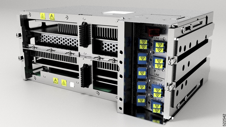
Cisco Network Convergence System 1010
Cisco NCS 1010 is a next-generation optical line system that is optimized for ZR/ZR+ WDM interfaces in the routers. It provides point-to-point connectivity between routers with WDM interfaces and multiplex WDM signals from multiple routers over single fiber. In addition, it supports ROADM express of up to 8 degrees. It caters to both C-band only and C+L combined WDM transmission to maximize capacity. Cisco NCS 1010 is a 3RU chassis that has an in-built External Interface Timing Unit (EITU) and the following field-replaceable modules.
-
Controller
-
Two power supply units
-
Two fan trays
-
Fan filter
-
Line card
There are five different variants of the line card:
-
OLT-C Line Card―C-band Optical Line Terminal without Raman
-
OLT-R-C Line Card―C-band Optical Line Terminal with Raman
-
ILA-C Line Card―C-band In-Line Amplifier without Raman
-
ILA-R-C Line Card―C-band In-Line Amplifier with one side Raman
-
ILA-2R-C―C-band In-Line Amplifier with both sides Raman

NCS 1010 for Routed Optical Networking
The following features of the NCS 1010 Optical Line Systems make it ideal for Routed Optical Networking:
-
Support for low-power coherent sources
-
Ingress EDFA amplifier on OLTs to support 400ZR and OpenZR+ DCOs.
-
Low loss couplers to support 95/140 G Baud-Rates that need higher Rx power.
-
-
Capacity scaling built-in by design
-
Hitless upgrade from C band to C+L band
-
Embedded channelized ASE for consistency in performance from day-1 to full capacity growth
-
33-port Twin-WSS architecture to use as express or add/drop
-
-
Simplicity of the OLS
-
Simpler patching – integrated module
-
Independent degree operation
-
Automated turn-up
-
Full spectrum loading from the start
-
DGE on ILAs for equalization and better control of Raman Gain ripple
-
-
Automation of entire life cycle
-
Device automation - ZTP, OC YANG config, Telemetry
-
Automated E2E turn-up with embedded control loops
-
Automated Connection Verification for patch loss checks at each site
-
Enhanced visibility - OTDR, OSC, OCM
-
Cisco NCS 1000 32-Channel Mux/Demux Patch Panel
The Cisco NCS 1000 32-Channel Mux/Demux patch panels are a pair of passive Athermal Arrayed Waveguide Grating (AAWG) base modules (PIDs NCS1K-MD-32O-C and NCS1K-MD32E-C). Each mux/demux panel has 32 channels and works as an add/drop unit for the OLT-C and OLT-R-C line cards. Each mux/demux panel allows the multiplexing and demultiplexing of 32 channels with 150-GHz spacing. 75-GHz frequency shift exists between the ODD and EVEN panels. When both panels are used on the same OLT (OLT-C and OLT-R-C) line cards, the combined capacity becomes 64 channels with 75-GHz spacing. Each mux/demux panel provides a wide optical pass-band support. When used as a standalone, each panel acts as an add/drop unit for 32 channels at 140 gigabauds.
The NCS1K-MD32O/E-C panel operates in C-band. The Cisco NCS 1000 Mux/Demux patch panels are fully passive. The units are powered with a USB 3.0 connection in the NCS 1010 chassis. The panels monitor signals, verify connections, and retrieve the inventory data.
Cisco NCS 1000 Breakout Patch Panel and Modules
Cisco NCS 1000 Breakout Patch Panel
Cisco NCS 1000 Breakout Patch Panel is a colorless breakout-modular patch panel. It is powered by the NCS 1010 chassis using a single USB 3.0 cable. The breakout panel contains four USB 2.0 connections that power the passive optical modules. It allows connections between the OLT-C and OLT-R-C line cards that are installed in the NCS 1010 chassis and the optical passive modules using MPO cables. The breakout panel is 4 RU high and has adjustable fiber guides for fiber routing. The empty slots are covered with dummy covers.
The NCS1K-BRK-SA breakout panel is a 4RU breakout patch panel. It interfaces four passive optical modules with the NCS 1010 chassis. The breakout panel supports up to 72 colorless mux/demux channels. The breakout panel supports 8-directional interconnections.
The panel is shipped with USB 2.0 connectors that are connected to the corresponding dummy covers. The plastic transparent cover can be installed in front of the panel for fiber protection. The panel is designed to fit a 19-inch rack. The panel can also be installed on ETSI and 23-inch rack using adapter brackets.
Cisco NCS 1000 Breakout Modules
The Cisco NCS 1000 Breakout Modules are a set of three optical breakout units. The modules can be connected to the A/D 4-11, A/D 12-19, A/D 20-27 and A/D 28-33 MPO connector ports of the OLT-C and OLT-R-C line cards to provide ROADM node internal connections and for local channels add/drop. The breakout panel supports the following passive optical modules:
NCS1K-BRK-8
The NCS1K-BRK-8 module provides the breakout of 16 fibers from an MPO-24 connector to eight duplex line card connectors. It essentially performs an optical connection adaptation of MPO-to-LC connectors for the ADD/DROPi signals of the MPO ports of OLT line cards. For each port (MPO and LC), power monitors with tone detection capability are available. A filtered optical loopback (191.175 THz) from one MPO input port (fiber-1) to all MPO output ports is available for connection verification.
NCS1K-BRK-24
The NCS1K-BRK-24 module provides the breakout of 16 fibers from an MPO-24 connector to 24 duplex LC connectors. The signals on each fiber from the MPO input ports are split over three LC output ports by a 1x3 optical splitter. The signals from the three adjacent input LC ports are combined into a single MPO fiber output port through a 1x3 optical coupler. For each port (MPO and LC), power monitors with tone detection capability are available. A filtered optical loopback (191.175 THz) from one MPO input port (fiber-1) to all MPO output ports is available for connection verification.
For more information on Cisco Network Convergence System 1010, see the Cisco Network Convergence System 1010 Data Sheet .
 Feedback