Alarm Propagation Scenarios

In an optical network, alarm propagation defines how different alarms propagate in a larger link during any failure in the network. The alarm correlation algorithm suppresses the lower-priority alarms on each device in the network. Hence, the network administrator can assess the health of the optical network and detect the root cause of the problem by focusing only on the significant alarms on the node.

This chapter covers the alarms that are active and suppressed during the common alarm propagation scenarios when operating the NCS 1014 chassis.

Client Unidirectional Receiver Fiber Cut

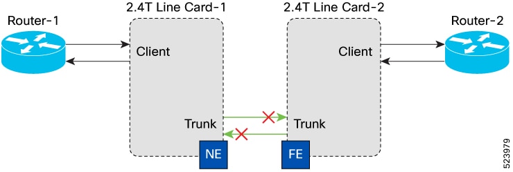
When there is a client unidirectional receiver fiber cut between Router-1 and 2.4T line card-1, alarms are raised and suppressed at the respective ports of each node.

This figure displays a client unidirectional receiver fiber cut.

Figure 1. Client Unidirectional Receiver Fiber Cut

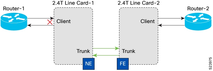
These tables list the alarms raised at the respective ports of each node.

Table 1. Active and Suppressed Alarms for Near End (NE) Interface Faults

NE Interfaces

Active Alarms

Suppressed Alarms

Router 1

Remote Fault

No Alarms

NE_Client

SIGLOSS

No Alarms

NE_Trunk

No Alarms

No Alarms

Table 2. Active and Suppressed Alarms for Far End (FE) Interface Faults

FE Interfaces

Active Alarms

Suppressed Alarms

Router 2

  • Local Fault

  • LOCAL-DEG-SER

No Alarms

FE_Client

Remote Fault

No Alarms

FE_Trunk

OPUK-CSF

No Alarms

1 The capability of the router is the determining factor for LD (LOCAL-DEG-SER) reporting. According to IEEE Standard 802.3, implementing Forward Error Correction (FEC) alarms is optional. However, if these alarms are supported, the router inserts an RD (Remote-Deg-Ser) in the upstream direction in response to the LD (Local-FEC -Deg-Ser) alarm.

Client Unidirectional Transmitter Fiber Cut

When there is a client unidirectional transmitter fiber cut between Router-1 and 2.4T Line Card-1, alarms are raised and suppressed at the respective ports of each node.

This figure displays the client unidirectional transmitter fiber cut.

Figure 2. Client Unidirectional Transmitter Fiber Cut

The following tables list the alarms that are raised at the respective ports of each node.

Table 3. Active and Suppressed Alarms for Near End (NE) Interface Faults

Node

Active Alarms

Suppressed Alarms

Router 1

LOSS

No Alarms

NE_Client

Remote Fault

No Alarms

NE_Trunk

No Alarms

No Alarms

Table 4. Active and Suppressed Alarms for Far End (FE) Interface Faults

Node

Active Alarms

Suppressed Alarms

Router 2

Remote Fault

No Alarms

FE_Client

No Alarms

No Alarms

FE_Trunk

No Alarms

No Alarms

Client Bi-directional Fiber Cut

When there is a client bi-directional fiber cut between Router-1 and 2.4T Line Card-1, alarms are raised and suppressed at the respective ports of each node.

This figure displays a client bi-directional receiver fiber cut.

Figure 3. Client Bi-directional Fiber Cut

These tables list the alarms that are raised at the respective ports of each node.

Table 5. Active and Suppressed Alarms for Near End (NE) Interface Faults

Node

Active Alarms

Suppressed Alarms

Router 1

LOSS

No Alarms

NE_Client

SIGLOSS

No Alarms

NE_Trunk

No Alarms

No Alarms

Table 6. Active and Suppressed Alarms for Far End (FE) Interface Faults

Node

Active Alarms

Suppressed Alarms

Router 2

  • Local Fault

  • LD2

No Alarms

FE_Client

Remote Fault

No Alarms

FE_Trunk

OPUK-CSF

No Alarms

2 The capability of the router is the determining factor for LD (LOCAL-DEG-SER) reporting. According to IEEE Standard 802.3, implementing Forward Error Correction (FEC) alarms is optional. However, if these alarms are supported, the router inserts an RD (Remote-Deg-Ser) in the upstream direction in response to the LD (Local-FEC -Deg-Ser) alarm.

Client Unidirectional Loss of Synchronization on Data Interface

When there is a client unidirectional Loss of Synchronization on Data Interface (SYNCLOSS) between Router-1 and 2.4T line card-1, alarms are raised and suppressed at the respective ports of each node.

This figure displays the unidirectional SYNCLOSS.

Figure 4. Client Unidirectional SYNCLOSS

These tables list the alarms that are raised and suppressed at the respective ports of each node.

Table 7. Active and Suppressed Alarms for Near End (NE) Interface Faults

Node

Active Alarms

Suppressed Alarms

Router 1

Remote Fault

No Alarms

NE_Client

SYNCLOSS

No Alarms

NE_Trunk

No Alarms

No Alarms

Table 8. Active and Suppressed Alarms for Far End (FE) Interface Faults

Node

Active Alarms

Suppressed Alarms

Router 2

  • Local Fault

  • LOCAL-DEG-SER3

No Alarms

FE_Client

Remote Fault

No Alarms

FE_Trunk

OPUK-CSF

No Alarms

3 The capability of the router is the determining factor for LD (LOCAL-DEG-SER) reporting. According to IEEE Standard 802.3, implementing Forward Error Correction (FEC) alarms is optional. However, if these alarms are supported, the router inserts an RD (Remote-Deg-Ser) in the upstream direction in response to the LD (Local-FEC -Deg-Ser) alarm.

Client Unidirectional LOCAL FAULT

When there is a client unidirectional LOCAL FAULT (LF) between Router-1 and 2.4T Line Card-1, alarms are raised and suppressed at the respective ports of each node.

This figure displays unidirectional LF.

Figure 5. Client Unidirectional LF

These tables list the alarms that are raised and suppressed at the respective ports of each node.

Table 9. Active and Suppressed Alarms for Near End (NE) Interface Faults

Node

Active Alarms

Suppressed Alarms

Router 1

Remote Fault

No Alarms

NE_Client

Local Fault

No Alarms

NE_Trunk

No Alarms

No Alarms

Table 10. Active and Suppressed Alarms for Far End (FE) Interface Faults

Node

Active Alarms

Suppressed Alarms

Router 2

Local Fault

No Alarms

FE_Client

Remote Fault

No Alarms

FE_Trunk

No Alarms

No Alarms

Client Unidirectional REMOTE-FAULT

When there is a client unidirectional REMOTE-FAULT (RF) between Router-1 and 2.4T Line Card-1, alarms are raised and suppressed at the respective ports of each node.

This figure displays unidirectional RF.

Figure 6. Client Unidirectional RF

These tables list the alarms that are raised and suppressed at the respective ports of each node:

Table 11. Active and Suppressed Alarms for Near End (NE) Interface Faults

Node

Active Alarms

Suppressed Alarms

Router 1

Any fault can be triggered (In case of LOSS/LF, Remote fault is triggered).

No Alarms

NE_Client

Remote Fault

No Alarms

NE_Trunk

No Alarms

No Alarms

Table 12. Active and Suppressed Alarms for Far End (FE) Interface Faults

Node

Active Alarms

Suppressed Alarms

Router 2

Remote Fault

No Alarms

FE_Client

No Alarms

No Alarms

FE_Trunk

No Alarms

No Alarms

Client Unidirectional High Symbol Error Rate

When there is a client unidirectional High Symbol Error Rate (Hi-SER) between Router-1 and 2.4T Line Card-1, alarms are raised and suppressed at the respective ports of each node.

This figure displays client unidirectional Hi-SER fault.

Figure 7. Client Unidirectional HI-SER

These tables list the alarms that are raised at the respective ports of each node:

Table 13. Active and Suppressed Alarms for Near End (NE) Interface Faults

Node

Active Alarms

Suppressed Alarms

Router-1

No Alarms

No Alarms

NE_Client

  • HI-SER

  • DEG-SER

No Alarms

NE_Trunk

No Alarms

No Alarms

Table 14. Active and Suppressed Alarms for Far End (FE) Interface Faults

Node

Active Alarms

Suppressed Alarms

Router -2

LOCAL-DEG-SER4

No Alarms

FE_Client

No Alarms

No Alarms

FE_Trunk

No Alarms

No Alarms

4 The capability of the router is the determining factor for LD (LOCAL-DEG-SER) reporting. According to IEEE Standard 802.3, implementing Forward Error Correction (FEC) alarms is optional. However, if these alarms are supported, the router inserts an RD (Remote-Deg-Ser) in the upstream direction in response to the LD (Local-FEC -Deg-Ser) alarm.

Client Unidirectional Degraded Symbol Error Rate

When there is a client unidirectional Degraded Symbol Error Rate (DEG-SER) between Router-1 and 2.4T Line Card-1, alarms are raised and suppressed at the respective ports of each node.

This figure displays client unidirectional DEG-SER:

Figure 8. Client Unidirectional DEG-SER

These tables list the alarms that are raised at the respective ports of each node:

Table 15. Active and Suppressed Alarms for Near End (NE) Interface Faults

Node

Active Alarms

Suppressed Alarms

Router-1

No Alarms

No Alarms

NE_Client

DEG-SER

Example: DEG-SER :DECLARE:

FourHundredGigECtrlr0/1/0/1:

No Alarms

NE_Trunk

No Alarms

No Alarms

Table 16. Active and Suppressed Alarms for Far End (FE) Interface Faults

Node

Active Alarms

Suppressed Alarms

Router-2

LOCAL-DEG-SER5

No Alarms

FE_Client

No Alarms

No Alarms

FE_Trunk

No Alarms

No Alarms

5 The capability of the router is the determining factor for LD (LOCAL-DEG-SER) reporting. According to IEEE Standard 802.3, implementing Forward Error Correction (FEC) alarms is optional. However, if these alarms are supported, the router inserts an RD (Remote-Deg-Ser) in the upstream direction in response to the LD (Local-FEC -Deg-Ser) alarm.

Client Unidirectional LOCAL-DEG-SER

When there is a client unidirectional LOCAL-DEG-SER (LD) between Router-1 and 2.4T Line Card-1, alarms are raised and suppressed at the respective ports of each node.

This figure displays client unidirectional LD.

Figure 9. Client Unidirectional LD

These tables list the alarms that are raised at the respective ports of each node.

Table 17. Active and Suppressed Alarms for Near End (NE) Interface Faults

Node

Active Alarms

Suppressed Alarms

Router-1

No Alarms

No Alarms

NE_Client

LOCAL-DEG-SER

No Alarms

NE_Trunk

No Alarms

No Alarms

Table 18. Active and Suppressed Alarms for Far End (FE) Interface Faults

Node

Active Alarms

Suppressed Alarms

Router 2

LOCAL-DEG-SER6

No Alarms

FE_Client

No Alarms

No Alarms

FE_Trunk

No Alarms

No Alarms

6 The capability of the router is the determining factor for LD (LOCAL-DEG-SER) reporting. According to IEEE Standard 802.3, implementing Forward Error Correction (FEC) alarms is optional. However, if these alarms are supported, the router inserts an RD (Remote-Deg-Ser) in the upstream direction in response to the LD (Local-FEC -Deg-Ser) alarm.

Client Unidirectional REMOTE-DEG-SER

When there is a client unidirectional REMOTE-DEG-SER (RD) between Router-1 and 2.4T Line Card-1, alarms are raised and suppressed at the respective ports of each node.

This figure displays client unidirectional RD.

Figure 10. Client Unidirectional RD

These tables list the alarms that are raised at the respective ports of each node.

Table 19. Active and Suppressed Alarms for Near End (NE) Interface Faults

Node

Active Alarms

Suppressed Alarms

Router 1

LOCAL-DEG-SER7

No Alarms

NE_Client

REMOTE-DEG-SER

No Alarms

NE_Trunk

No Alarms

No Alarms

7 The capability of the router is the determining factor for LD (LOCAL-DEG-SER) reporting. According to IEEE Standard 802.3, implementing Forward Error Correction (FEC) alarms is optional. However, if these alarms are supported, the router inserts an RD (Remote-Deg-Ser) in the upstream direction in response to the LD (Local-FEC -Deg-Ser) alarm.
Table 20. Active and Suppressed Alarms for Far End (FE) Interface Faults

Node

Active Alarms

Suppressed Alarms

Router 2

RD

No Alarms

FE_Client

No Alarms

No Alarms

FE_Trunk

No Alarms

No Alarms

Client Unidirectional Improper Removal

When there is a client unidirectional Improper Removal (IMPROPRMVL) between Router-1 and 2.4T Line Card-1, alarms are raised and suppressed at the respective ports of each node.

This figure displays client unidirectional IMPROPRMVL.

Figure 11. Client Unidirectional IMPROPRMVL

These tables lists the alarms that are raised at the respective ports of each node.

Table 21. Active and Suppressed Alarms for Near End (NE) Interface Faults

Node

Active Alarms

Suppressed Alarms

Router-1

LOS

No Alarms

NE_Client

IMPROPRMVL

No Alarms

NE_Trunk

No Alarms

No Alarms

Table 22. Active and Suppressed Alarms for Far End (FE) Interface Faults

Node

Active Alarms

Suppressed Alarms

Router-2

  • Local Fault

  • LOCAL-DEG-SER8

No Alarms

FE_Client

Remote Fault

No Alarms

FE_Trunk

OPUK-CSF

No Alarms

8 The capability of the router is the determining factor for LD (LOCAL-DEG-SER) reporting. According to IEEE Standard 802.3, implementing Forward Error Correction (FEC) alarms is optional. However, if these alarms are supported, the router inserts an RD (Remote-Deg-Ser) in the upstream direction in response to the LD (Local-FEC -Deg-Ser) alarm.

Trunk Unidirectional Fiber Cut

When there is a trunk unidirectional fiber cut between 2.4T line card-1 and 2.4T line card-2, alarms are raised and suppressed at the respective ports of each node.

This figure displays trunk unidirectional fiber cut.

Figure 12. Trunk Unidirectional Fiber Cut

These tables list the alarms that are raised at the respective ports of each node.

Table 23. Active and Suppressed Alarms for Near End (NE) Interface Faults

Node

Active Alarms

Suppressed Alarms

Router-1

Remote Fault

No Alarms

NE_Client

No Alarms

No Alarms

NE_Trunk

  • FLEXO-RDI

  • ODUK-BDI-PM

No Alarms

Table 24. Active and Suppressed Alarms for Far End (FE) Interface Faults

Node

Active Alarms

Suppressed Alarms

Router-2

  • Local Fault

  • LOCAL-DEG-SER9

No Alarms

FE_Client

Remote Fault

No Alarms

FE_Trunk

LOS-P

No Alarms

9 The capability of the router is the determining factor for LD (LOCAL-DEG-SER) reporting. According to IEEE Standard 802.3, implementing Forward Error Correction (FEC) alarms is optional. However, if these alarms are supported, the router inserts an RD (Remote-Deg-Ser) in the upstream direction in response to the LD (Local-FEC -Deg-Ser) alarm.

Trunk Bidirectional Fiber Cut

When there is a trunk bi-directional fiber cut between 2.4T line card-1 and 2.4T line card-2 alarms are raised and suppressed at the respective ports of each node.

This figure displays trunk bidirectional fiber cut.

Figure 13. Trunk Bi-directional Fiber Cut

These tables list the alarms that are raised at the respective ports of each node.

Table 25. Near End (NE) Interface Faults: Active and Suppressed Alarms

Node

Active Alarms

Suppressed Alarms

Router 1

  • LOCAL-DEG-SER10

  • Local Fault

No Alarms

NE_Client

Remote Fault

No Alarms

NE_Trunk

LOS-P

No Alarms

10 The capability of the router is the determining factor for LD (LOCAL-DEG-SER) reporting. According to IEEE Standard 802.3, implementing Forward Error Correction (FEC) alarms is optional. However, if these alarms are supported, the router inserts an RD (Remote-Deg-Ser) in the upstream direction in response to the LD (Local-FEC -Deg-Ser) alarm.
Table 26. Active and Suppressed Alarms for Far End (FE) Interface Faults

Node

Active Alarms

Suppressed Alarms

Router 2

  • Local Fault

  • LOCAL-DEG-SER11

No Alarms

FE_Client

Remote Fault

No Alarms

FE_Trunk

LOS-P

No Alarms

11 The capability of the router is the determining factor for LD (LOCAL-DEG-SER) reporting. According to IEEE Standard 802.3, implementing Forward Error Correction (FEC) alarms is optional. However, if these alarms are supported, the router inserts an RD (Remote-Deg-Ser) in the upstream direction in response to the LD (Local-FEC -Deg-Ser) alarm.

Trunk Frequency Mismatch - Complete Offset with 150GHz Spacing

When there is a trunk frequency mismatch between 2.4T line card-1 and 2.4T line card-2 alarms, are raised and suppressed at the respective ports of each node.

This figure displays trunk frequency mismatch for complete offset with 150GHz spacing.

Figure 14. Trunk Frequency Mismatch

These tables list the alarms that are raised at the respective ports of each node.

Table 27. Active and Suppressed Alarms for Near End (NE) Interface Faults

Node

Active Alarms

Suppressed Alarms

Router-1

  • Local Fault

  • LOCAL-DEG-SER12

No Alarms

NE_Client

Remote Fault

No Alarms

NE_Trunk

LOS-P

No Alarms

12 The capability of the router is the determining factor for LD (LOCAL-DEG-SER) reporting. According to IEEE Standard 802.3, implementing Forward Error Correction (FEC) alarms is optional. However, if these alarms are supported, the router inserts an RD (Remote-Deg-Ser) in the upstream direction in response to the LD (Local-FEC -Deg-Ser) alarm.
Table 28. Active and Suppressed Alarms for Far End (FE) Interface Faults

Node

Active Alarms

Suppressed Alarms

Router -2

  • Local Fault

  • LOCAL-DEG-SER13

No Alarms

FE_Client

Remote Fault

No Alarms

FE_Trunk

LOS-P

No Alarms

13 The capability of the router is the determining factor for LD (LOCAL-DEG-SER) reporting. According to IEEE Standard 802.3, implementing Forward Error Correction (FEC) alarms is optional. However, if these alarms are supported, the router inserts an RD (Remote-Deg-Ser) in the upstream direction in response to the LD (Local-FEC -Deg-Ser) alarm.

Trunk Frequency Mismatch - Partial Offset with 75GHz Spacing

When there is a trunk frequency mismatch between 2.4T line card-1 and 2.4T line card-2 alarms, are raised and suppressed at the respective ports of each node.

The following figure displays trunk frequency mismatch for partial offset with 75GHz spacing::

Figure 15. Trunk Frequency Mismatch

These tables list the alarms that are raised at the respective ports of each node.

Table 29. Active and Suppressed Alarms for Near End (NE) Interface Faults

NE Interface Faults

Node

Active Alarms

Suppressed Alarms

Router-1

No Alarms

NE_Client

RF

Example, RF: DECLARE :FourHundredGigECtrlr0/1/0/1

No Alarms

NE_Trunk

FLEXO-LOF & OSNR

Example:

FLEXO-LOF :DECLARE :CoherentDSP0/1/0/0:

OSNR :DECLARE :Optics0/1/0/0

No Alarms

14 The capability of the router is the determining factor for LD (LOCAL-DEG-SER) reporting. According to IEEE Standard 802.3, implementing Forward Error Correction (FEC) alarms is optional. However, if these alarms are supported, the router inserts an RD (Remote-Deg-Ser) in the upstream direction in response to the LD (Local-FEC -Deg-Ser) alarm.
Table 30. Active and Suppressed Alarms for Far End (FE) Interface Faults

FE Interface Faults

Node

Active Alarms

Suppressed Alarms

Router -2

No Alarms

FE_Client

RF

Example, RF: DECLARE :

FourHundredGigECtrlr0/1/0/1

No Alarms

FE_Trunk

FLEXO-LOF & OSNR

Example: FLEXO-LOF :DECLARE :

CoherentDSP0/1/0/0:

OSNR :DECLARE :Optics0/1/0/0

No Alarms

15 The capability of the router is the determining factor for LD (LOCAL-DEG-SER) reporting. According to IEEE Standard 802.3, implementing Forward Error Correction (FEC) alarms is optional. However, if these alarms are supported, the router inserts an RD (Remote-Deg-Ser) in the upstream direction in response to the LD (Local-FEC -Deg-Ser) alarm.

Trunk Unidirectional Loss of Frame

When there is a trunk unidirectional Loss of Frame (LOF) between 2.4T line card-1 and 2.4T line card-2, alarms are raised and suppressed at the respective ports of each node.

This figure displays trunk LOF.

Figure 16. Trunk Unidirectional LOF

These tables list the alarms that are raised at the respective ports of each node.

Table 31. Active and Suppressed Alarms for Near End (NE) Interface Faults

Node

Active Alarms

Suppressed Alarms

Router-1

RF

No Alarms

NE_Client

No Alarms

No Alarms

NE_Trunk

  • FLEXO-RDI

    Example: FLEXO-RDI :DECLARE :CoherentDSP0/1/0/0:

  • ODUK-BDI-PM

    Example: ODUK-BDI-PM :DECLARE :ODU-FLEX0/1/0/0/1:

No Alarms

Table 32. Active and Suppressed Alarms for Far End (FE) Interface Faults

Node

Active Alarms

Suppressed Alarms

Router -2

No Alarms

FE_Client

RF

Example, RF: DECLARE :FourHundredGigECtrlr0/1/0/1

No Alarms

FE_Trunk

  • FLEXO-LOF

    Example: FLEXO-LOF :DECLARE :CoherentDSP0/1/0/0:

  • OSNR

    Example: OSNR:DECLARE :Optics0/1/0/0:

No Alarms

16 The capability of the router is the determining factor for LD (LOCAL-DEG-SER) reporting. According to IEEE Standard 802.3, implementing Forward Error Correction (FEC) alarms is optional. However, if these alarms are supported, the router inserts an RD (Remote-Deg-Ser) in the upstream direction in response to the LD (Local-FEC -Deg-Ser) alarm.

Trunk Group ID Mismatch

When there is a trunk Group ID Mismatch (GIDM) between 2.4T line card-1 and 2.4T line card-2, alarms are raised and suppressed at the respective ports of each node.

The following figure displays trunk GIDM:

Figure 17. Trunk GIDM

The following tables list the alarms that are raised at the respective ports of each node:

Table 33. Active and Suppressed Alarms for Near End (NE) Interface Faults

Node

Active Alarms

Suppressed Alarms

Router-1

  • LD

  • LF

No Alarms

NE_Client

RF

Example: RF :DECLARE :FourHundredGigECtrlr0/1/0/1

No Alarms

NE_Trunk

Flexo-GIDM

Example: Flexo-GIDM :DECLARE :CoherentDSP0/1/0/0:

No Alarms

Table 34. Active and Suppressed Alarms for Far End (FE) Interface Faults

Node

Active Alarms

Suppressed Alarms

Router-2

No Alarms

FE_Client

RF

Example, RF: DECLARE :FourHundredGigECtrlr0/1/0/1

No Alarms

FE_Trunk

FLEXO-GIDM

Example: FLEXO-GIDM :DECLARE :CoherentDSP0/1/0/0:

No Alarms

17 The capability of the router is the determining factor for LD (LOCAL-DEG-SER) reporting. According to IEEE Standard 802.3, implementing Forward Error Correction (FEC) alarms is optional. However, if these alarms are supported, the router inserts an RD (Remote-Deg-Ser) in the upstream direction in response to the LD (Local-FEC -Deg-Ser) alarm.

Trunk Unidirectional OTUK-TIM

When there is a trunk unidirectional OTUK-TIM between 2.4T line card-1 and 2.4T line card-2, alarms are raised and suppressed at the respective ports of each node.

This figure displays trunk unidirectional OTUK-TIM.

Figure 18. Trunk Unidirectional OTUK-TIM

These tables list the alarms that are raised at the respective ports of each node.

Table 35. Active and Suppressed Alarms for Near End (NE) Interface Faults

Node

Active Alarms

Suppressed Alarms

Router -1

No Alarms

No Alarms

NE_Client

No Alarms

No Alarms

NE_Trunk

No Alarms

No Alarms

Table 36. Active and Suppressed Alarms for Far End (FE) Interface Faults

Node

Active Alarms

Suppressed Alarms

Router-2

No Alarms

No Alarms

FE_Client

No Alarms

No Alarms

FE_Trunk

OTUK-TIM

Example: OTUK-TIM :DECLARE :CoherentDSP0/1/0/0:

No Alarms

Trunk Unidirectional Improper Removal

When there is a trunk optics Improper Removal (IMPROPRMVL) between 2.4T line card-1 and 2.4T line card-2, alarms are raised and suppressed at the respective ports of each node.

This figure displays trunk optics IMPROPRMVL.

Figure 19. Trunk Unidirectional IMPROPRMVL

These tables list the alarms that are raised at the respective ports of each node.

Table 37. Active and Suppressed Alarms for Near End (NE) Interface Faults

Node

Active Alarms

Suppressed Alarms

Router-1

No Alarms

NE_Client

RF

Example:

RF :DECLARE :FourHundredGigECtrlr0/1/0/1

No Alarms

NE_Trunk

LOS-P

No Alarms

18 The capability of the router is the determining factor for LD (LOCAL-DEG-SER) reporting. According to IEEE Standard 802.3, implementing Forward Error Correction (FEC) alarms is optional. However, if these alarms are supported, the router inserts an RD (Remote-Deg-Ser) in the upstream direction in response to the LD (Local-FEC -Deg-Ser) alarm.
Table 38. Far End (FE) Interface Faults: Active and Suppressed Alarms

Node

Active Alarms

Suppressed Alarms

Router-2

No Alarms

FE_Client

RF

Example: RF :DECLARE :FourHundredGigECtrlr0/1/0/1

No Alarms

FE_Trunk

IMPROPRMVL

Example:

IMPROPRMVL :DECLARE :Optics0/1/0/1:

No Alarms

19 The capability of the router is the determining factor for LD (LOCAL-DEG-SER) reporting. According to IEEE Standard 802.3, implementing Forward Error Correction (FEC) alarms is optional. However, if these alarms are supported, the router inserts an RD (Remote-Deg-Ser) in the upstream direction in response to the LD (Local-FEC -Deg-Ser) alarm.