OTS Controllers
There are two types of controller models supported on Cisco NCS 1010. They are:
ILA Controller Model
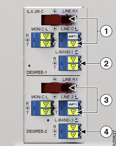
When the NCS1K-ILA-2R-C, NCS1K-ILA-R-C and NCS1K-ILA-C cards are brought up, four OTS controllers are created by default. The OTS controllers are:
-
OTS controllers for side 1:
-
LINE 0 port: ots 0/0/0/0 ( band line OTS controller)
-
L-BAND 1 port: ots 0/0/0/1 (L band line OTS controller)
-
-
OTS controllers for side 2:
-
LINE 2 port: ots 0/0/0/2 ( band line OTS controller)
-
L-BAND 3 port: ots 0/0/0/3 (L band line OTS controller)
-
The following figures and tables show the three ILA variants and the mapping between physical ports and controllers:
|
1 |
Parent Controller: OTS0/0/0/0 Child Controller: OSC0/0/0/0, DFB0/0/0/0, Line OTS-OCH 0/0/0/0/x |
|
2 |
Parent Controller: OTS0/0/0/1 |
|
3 |
Parent Controller: OTS0/0/0/2 Child Controller: OSC0/0/0/2, DFB0/0/0/2, Line OTS-OCH 0/0/0/2/x |
|
4 |
Parent Controller: OTS0/0/0/3 |
|
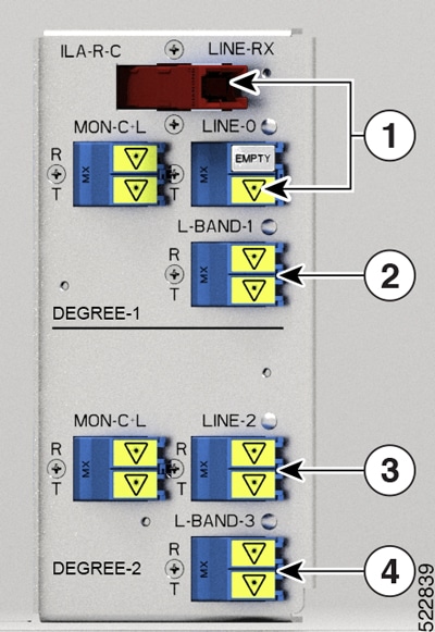
1 |
Parent Controller: OTS0/0/0/0 Child Controller: OSC0/0/0/0, DFB0/0/0/0, Line OTS-OCH 0/0/0/0/x |
|
2 |
Parent Controller: OTS0/0/0/1 |
|
3 |
Parent Controller: OTS0/0/0/2 Child Controller: OSC0/0/0/2, Line OTS-OCH 0/0/0/2/x |
|
4 |
Parent Controller: OTS0/0/0/3 |
|
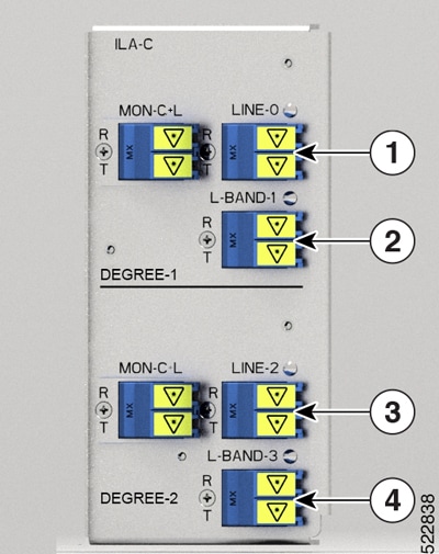
1 |
Parent Controller: OTS0/0/0/0 Child Controller: OSC0/0/0/0, Line OTS-OCH 0/0/0/0/x |
|
2 |
Parent Controller: OTS0/0/0/1 |
|
3 |
Parent Controller: OTS0/0/0/2 Child Controller: OSC0/0/0/2, Line OTS-OCH 0/0/0/2/x |
|
4 |
Parent Controller: OTS0/0/0/3 |
To view the card type, use the following command:
RP/0/RP0/CPU0:ios#show platformThe following output highlights the NCS1K-ILA-C card type for the ILA controller model.
Fri Mar 25 09:23:43.417 UTC
Node              Type                     State                    Config state
--------------------------------------------------------------------------------
0/RP0/CPU0        NCS1010-CNTLR-K9(Active) IOS XR RUN               NSHUT,NMON
0/PM0             NCS1010-AC-PSU           OPERATIONAL              NSHUT,NMON
0/PM1             NCS1010-AC-PSU           OPERATIONAL              NSHUT,NMON
0/FT0             NCS1010-FAN              OPERATIONAL              NSHUT,NMON
0/FT1             NCS1010-FAN              OPERATIONAL              NSHUT,NMON
0/0/NXR0          NCS1K-ILA-C              OPERATIONAL              NSHUT,NMON
0/2               NCS1K-BRK-SA             OPERATIONAL              NSHUT,NMON
RP/0/RP0/CPU0:ios#
The following output highlights the NCS1K-E-ILA-R-C card type for the ILA controller model.
Fri Jun  9 07:04:19.710 UTC
Node              Type                     State                    Config state
--------------------------------------------------------------------------------
0/RP0/CPU0        NCS1010-CNTLR-K9(Active) IOS XR RUN               NSHUT,NMON
0/PM0             NCS1010-AC-PSU           OPERATIONAL              NSHUT,NMON
0/PM1             NCS1010-AC-PSU           OFFLINE                  NSHUT,NMON
0/FT0             NCS1010-FAN              OPERATIONAL              NSHUT,NMON
0/FT1             NCS1010-FAN              OPERATIONAL              NSHUT,NMON
0/0/NXR0          NCS1K-E-ILA-R-C          OPERATIONAL              NSHUT,NMON
To view the OTS controller status on the ILA cards, use the show controller description command.
RP/0/RP0/CPU0:ios#show controller descriptionThe following output highlights the status of the OTS controller interfaces (ots0/0/0/0…ots0/0/0/3) on the ILA cards
Fri Mar 25 09:24:53.386 UTC

Interface                   Status          Description
--------------------------------------------------------------------------------
Osc0/0/0/0                  up
Osc0/0/0/2                  up
Ots0/0/0/0                  up
Ots0/0/0/1                  up
Ots0/0/0/2                  up
Ots0/0/0/3                  up
RP/0/RP0/CPU0:ios#
To view the parameters of the LINE 0 OTS controller, use the following command:
RP/0/RP0/CPU0:ios#show controllers ots 0/0/0/0The following output displays the parameters of the LINE 0 OTS controller ots 0/0/0/0.
Fri Mar 25 09:27:44.146 UTC

 Controller State: Up

 Transport Admin State: In Service

 LED State: Green

         Alarm Status:
         -------------
         Detected Alarms: None


         Alarm Statistics:
         -----------------
         LOW-TX-PWR = 0
         RX-LOS-P = 0
         RX-LOC = 0
         TX-POWER-FAIL-LOW = 0
         INGRESS-AUTO-LASER-SHUT = 0
         INGRESS-AUTO-POW-RED = 0
         INGRESS-AMPLI-GAIN-LOW = 0
         INGRESS-AMPLI-GAIN-HIGH = 0
         EGRESS-AUTO-LASER-SHUT = 0
         EGRESS-AUTO-POW-RED = 0
         EGRESS-AMPLI-GAIN-LOW = 0
         EGRESS-AMPLI-GAIN-HIGH = 0
         HIGH-TX-BR-PWR = 0
         HIGH-RX-BR-PWR = 0
         SPAN-TOO-SHORT-TX = 0
         SPAN-TOO-SHORT-RX = 0

         Parameter Statistics:
         ---------------------
         Total RX Power(C+L) = 20.00 dBm
         Total TX Power(C+L) = 20.00 dBm
         Total RX Power = 20.00 dBm
         Total TX Power = 23.01 dBm
         RX Signal Power = -30.00 dBm
         TX Signal Power = 20.00 dBm
         TX Voa Attenuation = 0.0 dB
         Egress Ampli Gain = 8.0 dB
         Egress Ampli Tilt = 0.0 dB
         Egress Ampli Gain Range = Normal
         Egress Ampli Safety Control mode = auto
         Egress Ampli Osri = OFF
         Egress Ampli Force Apr = OFF


         Configured Parameters:
         -------------
         TX Voa Attenuation = 0.0 dB
         Egress Ampli Gain = 8.0 dB
         Egress Ampli Tilt = 0.0 dB
         Egress Ampli Gain Range = Normal
         Egress Ampli Safety Control mode = auto
         Egress Ampli Osri = OFF
         Egress Ampli Force Apr = OFF
To view the parameters of the LINE 2 OTS controller, use the following command:
RP/0/RP0/CPU0:ios#show controllers ots 0/0/0/2The following output displays the parameters of the LINE 2 OTS controller ots 0/0/0/2.
Wed Jun 29 15:54:05.699 UTC

 Controller State: Up

 Transport Admin State: In Service

 LED State: Green

         Alarm Status:
         -------------
         Detected Alarms: None


         Alarm Statistics:
         -----------------
         RX-LOS-P = 0
         RX-LOC = 0
         TX-POWER-FAIL-LOW = 0
         INGRESS-AUTO-LASER-SHUT = 0
         INGRESS-AUTO-POW-RED = 0
         INGRESS-AMPLI-GAIN-LOW = 0
         INGRESS-AMPLI-GAIN-HIGH = 0
         EGRESS-AUTO-LASER-SHUT = 0
         EGRESS-AUTO-POW-RED = 0
         EGRESS-AMPLI-GAIN-LOW = 0
         EGRESS-AMPLI-GAIN-HIGH = 0
         HIGH-TX-BR-PWR = 0
         HIGH-RX-BR-PWR = 0
         SPAN-TOO-SHORT-TX = 0
         SPAN-TOO-SHORT-RX = 0

         Parameter Statistics:
         ---------------------
         Total RX Power(C+L) = 20.00 dBm
         Total TX Power(C+L) = 20.00 dBm
         Total RX Power = 20.00 dBm
         Total TX Power = 23.01 dBm
         RX Signal Power = -30.00 dBm
         TX Signal Power = 20.00 dBm
         TX Voa Attenuation = 0.0 dB
         Egress Ampli Gain = 8.0 dB
         Egress Ampli Tilt = 0.0 dB
         Egress Ampli Gain Range = Normal
         Egress Ampli Safety Control mode = auto
         Egress Ampli Osri = OFF
         Egress Ampli Force Apr = OFF


         Configured Parameters:
         -------------

         TX Voa Attenuation = 0.0 dB
         Egress Ampli Gain = 8.0 dB
         Egress Ampli Tilt = 0.0 dB
         Egress Ampli Gain Range = Normal
         Egress Ampli Safety Control mode = auto
         Egress Ampli Osri = OFF
         Egress Ampli Force Apr = OFF
The following output displays the parameters of the LINE 1 OTS controller ots 0/0/0/1.
RP/0/RP0/CPU0:OLT-C-14#show controllers ots 0/0/0/1
Mon Feb 27 20:34:00.257 UTC

 Controller State: Up

Transport Admin State: In Service

LED State: Green

Alarm Status:
-------------
Detected Alarms: None


Alarm Statistics:
-----------------
RX-LOS-P = 1
RX-LOC = 0
TX-POWER-FAIL-LOW = 2
INGRESS-AUTO-LASER-SHUT = 0
INGRESS-AUTO-POW-RED = 0
INGRESS-AMPLI-GAIN-LOW = 0
INGRESS-AMPLI-GAIN-HIGH = 0
EGRESS-AUTO-LASER-SHUT = 0
EGRESS-AUTO-POW-RED = 0
EGRESS-AMPLI-GAIN-LOW = 0
EGRESS-AMPLI-GAIN-HIGH = 0
HIGH-TX-BR-PWR = 0
HIGH-RX-BR-PWR = 0
SPAN-TOO-SHORT-TX = 0
SPAN-TOO-SHORT-RX = 0

Parameter Statistics:
---------------------
Total Rx Power = 19.39 dBm
Total Tx Power = 3.99 dBm


Configured Parameters:
-------------
OLT Controller Model
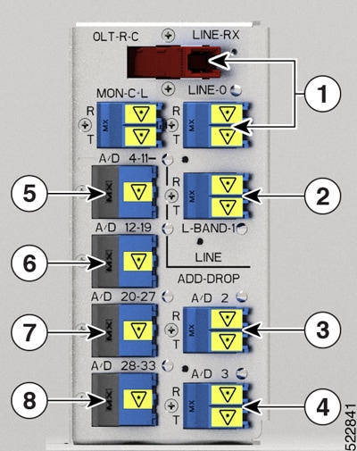
When the NCS1K-OLT-R-C, and NCS1K-OLT-C cards are brought up, 34 and OTS controllers are created by default for C band OLT cards respectively.
-
LINE 0 port: ots 0/0/0/0 (C band line OTS controller)
-
L-BAND 1 port: ots 0/0/0/1 (L band line OTS controller)
-
LC port: ots 0/0/0/2 ( Add1 Rx/Drop1 Tx OTS controller)
-
LC port: ots 0/0/0/3 ( Add2 Rx/Drop2 Tx OTS controller)
-
MPO ports: ots 0/0/0/4 to ots 0/0/0/11
-
MPO ports: ots 0/0/0/12 to ots 0/0/0/19
-
MPO ports: ots 0/0/0/20 to ots 0/0/0/27
-
MPO ports: ots 0/0/0/28 to ots 0/0/0/33
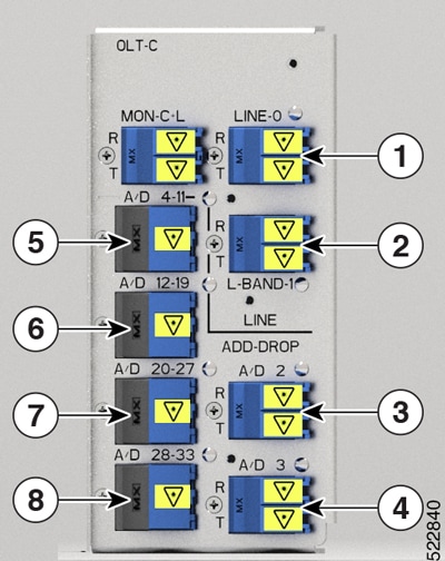
The following figures and tables show the two OLT variants and the mapping between physical ports and controllers:
|
1 |
Parent Controller: OTS0/0/0/0 Child Controller: OSC0/0/0/0, DFB0/0/0/0, Line OTS-OCH 0/0/0/0/x |
|
2 |
Parent Controller: OTS0/0/0/1 |
|
3 |
Parent Controller: OTS0/0/0/2 Child Controller: COM OTS-OCH 0/0/0/2/x |
|
4 |
Parent Controller: OTS0/0/0/3 Child Controller: COM OTS-OCH 0/0/0/3/x |
|
5 |
Parent Controller: OTS0/0/0/4-11 Child Controller: COM OTS-OCH 0/0/0/4-11/x |
|
6 |
Parent Controller: OTS0/0/0/12-19 Child Controller: COM OTS-OCH 0/0/0/12-19/x |
|
7 |
Parent Controller: OTS0/0/0/20-27 Child Controller: COM OTS-OCH 0/0/0/20-27/x |
|
8 |
Parent Controller: OTS0/0/0/28-33 Child Controller: COM OTS-OCH 0/0/0/28-33/x |
|
1 |
Parent Controller: OTS0/0/0/0 Child Controller: OSC0/0/0/0, Line OTS-OCH 0/0/0/0/x |
|
2 |
Parent Controller: OTS0/0/0/1 |
|
3 |
Parent Controller: OTS0/0/0/2 Child Controller: COM OTS-OCH 0/0/0/2/x |
|
4 |
Parent Controller: OTS0/0/0/3 Child Controller: COM OTS-OCH 0/0/0/3/x |
|
5 |
Parent Controller: OTS0/0/0/4-11 Child Controller: COM OTS-OCH 0/0/0/4-11/x |
|
6 |
Parent Controller: OTS0/0/0/12-19 Child Controller: COM OTS-OCH 0/0/0/12-19/x |
|
7 |
Parent Controller: OTS0/0/0/20-27 Child Controller: COM OTS-OCH 0/0/0/20-27/x |
|
8 |
Parent Controller: OTS0/0/0/28-33 Child Controller: COM OTS-OCH 0/0/0/28-33/x |
To view the platform information, use the following command:
RP/0/RP0/CPU0:ios#sThe following output highlights the NCS1K-OLT-R-C card type for the OLT controller model.
Wed Jun 29 16:00:14.373 UTC
Node              Type                     State                    Config state
--------------------------------------------------------------------------------
0/RP0/CPU0        NCS1010-CNTLR-K9(Active) IOS XR RUN               NSHUT,NMON
0/PM0             NCS1010-AC-PSU           OPERATIONAL              NSHUT,NMON
0/PM1             NCS1010-AC-PSU           OPERATIONAL              NSHUT,NMON
0/FT0             NCS1010-FAN              OPERATIONAL              NSHUT,NMON
0/FT1             NCS1010-FAN              OPERATIONAL              NSHUT,NMON
0/0/NXR0          NCS1K-OLT-R-C            OPERATIONAL              NSHUT,NMON
0/2               NCS1K-BRK-SA             OPERATIONAL              NSHUT,NMON
0/2/0             NCS1K-BRK-8              OPERATIONAL              NSHUT,NMON
0/2/1             NCS1K-BRK-16             OPERATIONAL              NSHUT,NMON
0/2/2             NCS1K-BRK-24             OPERATIONAL              NSHUT,NMON
RP/0/RP0/CPU0:ios#
To view the OTS controller status on the NCS1K-OLT-R-C line card, use the show controller description command.
RP/0/RP0/CPU0:ios#show controller descriptionThe following output highlights the status of the OTS controller interfaces (ots0/0/0/0…ots0/0/0/33) on the OLT cards
Wed Jun 29 16:03:59.914 UTC

Interface                   Status          Description
--------------------------------------------------------------------------------
Dfb0/0/0/0                  up
Osc0/0/0/0                  up
Ots0/0/0/0                  up
Ots0/0/0/1                  up
Ots0/0/0/2                  up
.
.
Output snipped
.
.
Ots0/0/0/30                 up
Ots0/0/0/31                 up
Ots0/0/0/32                 up
Ots0/0/0/33                 up
To view the parameters of the LINE 0 OTS controller, use the following command:
RP/0/RP0/CPU0:ios#show controllers ots 0/0/0/0The following output displays the parameters of the LINE 0 OTS controller ots 0/0/0/0.
Wed Jun 29 16:07:16.771 UTC

 Controller State: Up

 Transport Admin State: In Service

 LED State: Green

         Alarm Status:
         -------------
         Detected Alarms: None


         Alarm Statistics:
         -----------------
         RX-LOS-P = 0
         RX-LOC = 0
         TX-POWER-FAIL-LOW = 0
         INGRESS-AUTO-LASER-SHUT = 0
         INGRESS-AUTO-POW-RED = 0
         INGRESS-AMPLI-GAIN-LOW = 0
         INGRESS-AMPLI-GAIN-HIGH = 0
         EGRESS-AUTO-LASER-SHUT = 0
         EGRESS-AUTO-POW-RED = 0
         EGRESS-AMPLI-GAIN-LOW = 0
         EGRESS-AMPLI-GAIN-HIGH = 0
         HIGH-TX-BR-PWR = 0
         HIGH-RX-BR-PWR = 0
         SPAN-TOO-SHORT-TX = 0
         SPAN-TOO-SHORT-RX = 0

         Parameter Statistics:
         ---------------------
         Total RX Power(C+L) = -10.00 dBm
         Total TX Power(C+L) = 20.00 dBm
         Total RX Power = 20.00 dBm
         Total TX Power = 20.00 dBm
         RX Signal Power = 20.00 dBm
         TX Signal Power = 20.00 dBm
         TX Voa Attenuation = 0.0 dB
         Ingress Ampli Gain = 12.0 dB
         Ingress Ampli Tilt = 0.0 dB
         Ingress Ampli Gain Range = Normal
         Ingress Ampli Safety Control mode = auto
         Ingress Ampli Osri = OFF
         Ingress Ampli Force Apr = OFF
         Egress Ampli Gain = 16.0 dB
         Egress Ampli Tilt = 0.0 dB
         Egress Ampli Safety Control mode = auto
         Egress Ampli Osri = OFF
         Egress Ampli Force Apr = OFF


         Configured Parameters:
         -------------

         TX Voa Attenuation = 0.0 dB
         Ingress Ampli Gain = 12.0 dB
         Ingress Ampli Tilt = 0.0 dB
         Ingress Ampli Gain Range = Normal
         Ingress Ampli Safety Control mode = auto
         Ingress Ampli Osri = OFF
         Ingress Ampli Force Apr = OFF
         Egress Ampli Gain = 16.0 dB
         Egress Ampli Tilt = 0.0 dB
         Egress Ampli Safety Control mode = auto
         Egress Ampli Osri = OFF
         Egress Ampli Force Apr = OFF
To view the Raman parameters of the LINE 0 OTS controller, use the following command:
RP/0/RP0/CPU0:ios#show controllers ots 0/0/0/0 raman-infoThe following output displays the Raman parameters of the LINE 0 OTS controller ots 0/0/0/0.
Wed Mar 23 06:02:41.093 UTC

         Alarm Status:
         -------------
         Detected Alarms: None


         Alarm Statistics:
         -----------------
         RAMAN-AUTO-POW-RED = 0
         RAMAN-1-LOW-POW = 0
         RAMAN-2-LOW-POW = 0
         RAMAN-3-LOW-POW = 0
         RAMAN-4-LOW-POW = 0
         RAMAN-5-LOW-POW = 0
         RAMAN-1-HIGH-POW = 0
         RAMAN-2-HIGH-POW = 0
         RAMAN-3-HIGH-POW = 0
         RAMAN-4-HIGH-POW = 0
         RAMAN-5-HIGH-POW = 0

         Parameter Statistics:
         ---------------------
         Raman Safety Control mode = auto
         Raman Osri = OFF
         Raman Force Apr = OFF
         Composite Raman Power = 10.40 mW

         RAMAN Pump Info:
         ---------------------
         Instance        Wavelength(nm)  Power(mW)
          1               1424.00                 0.00
          2               1438.00                 0.10
          3               1457.00                 10.00
          4               1470.00                 0.20
          5               1495.00                 1.20


         Configured Parameters:
         -------------
         Raman Safety Control mode = auto
         Raman Osri = OFF
         Raman Force Apr = OFF

         RAMAN Pump Info:
         ---------------------
         Instance        Power(mW)
          1               45.00
          2               40.00
          3               40.00
          4               40.00
          5               35.00
To view the parameters on OTS port 2 or 3, use the following command:
RP/0/RP0/CPU0:ios#show controllers ots 0/0/0/2The following output displays the parameters of the OTS port 2 controller ots 0/0/0/2.
Wed Mar 23 06:14:53.465 UTC

 Controller State: Down

 Transport Admin State: In Service

 LED State: Red

         Alarm Status:
         -------------
         Detected Alarms:
                 RX-LOS-P
                 TX-POWER-FAIL-LOW

         Alarm Statistics:
         -----------------
         LOW-TX-PWR = 0
         RX-LOS-P = 1
         RX-LOC = 0
         TX-POWER-FAIL-LOW = 1
         INGRESS-AUTO-LASER-SHUT = 0
         INGRESS-AUTO-POW-RED = 0
         INGRESS-AMPLI-GAIN-LOW = 0
         INGRESS-AMPLI-GAIN-HIGH = 0
         EGRESS-AUTO-LASER-SHUT = 0
         EGRESS-AUTO-POW-RED = 0
         EGRESS-AMPLI-GAIN-LOW = 0
         EGRESS-AMPLI-GAIN-HIGH = 0
         HIGH-TX-BR-PWR = 0
         HIGH-RX-BR-PWR = 0
         SPAN-TOO-SHORT-TX = 0
         SPAN-TOO-SHORT-RX = 0

         Parameter Statistics:
         ---------------------
         Total RX Power = -50.00 dBm
         Total TX Power = -50.00 dBm
         Ingress Ampli Gain = 0.0 dB
         Ingress Ampli Tilt = 0.0 dB


         Configured Parameters:
         -------------
         Ingress Ampli Gain = 16.0 dB
         Ingress Ampli Tilt = 0.0 dB
RP/0/RP0/CPU0:ios#show controllers ots 0/0/0/1
Wed Mar 23 06:17:57.475 UTC

 Controller State: Down

 Transport Admin State: In Service

 LED State: Red

         Alarm Status:
         -------------
         Detected Alarms:
                 RX-LOS-P
                 TX-POWER-FAIL-LOW

         Alarm Statistics:
         -----------------
         LOW-TX-PWR = 0
         RX-LOS-P = 1
         RX-LOC = 0
         TX-POWER-FAIL-LOW = 1
         INGRESS-AUTO-LASER-SHUT = 0
         INGRESS-AUTO-POW-RED = 0
         INGRESS-AMPLI-GAIN-LOW = 0
         INGRESS-AMPLI-GAIN-HIGH = 0
         EGRESS-AUTO-LASER-SHUT = 0
         EGRESS-AUTO-POW-RED = 0
         EGRESS-AMPLI-GAIN-LOW = 0
         EGRESS-AMPLI-GAIN-HIGH = 0
         HIGH-TX-BR-PWR = 0
         HIGH-RX-BR-PWR = 0
         SPAN-TOO-SHORT-TX = 0
         SPAN-TOO-SHORT-RX = 0

         Parameter Statistics:
         ---------------------


         Configured Parameters:
         -------------
To view the parameters on the MPO port, use the following command:
RP/0/RP0/CPU0:ios#show controllers ots 0/0/0/33The following output displays the paramters for the MPO port ots 0/0/0/33.
Sun Apr 10 14:04:40.513 UTC

 Controller State: Up

 Transport Admin State: In Service

 LED State: Green

         Alarm Status:
         -------------
         Detected Alarms: None


         Alarm Statistics:
         -----------------
         RX-LOS-P = 0
         RX-LOC = 0
         TX-POWER-FAIL-LOW = 0
         INGRESS-AUTO-LASER-SHUT = 0
         INGRESS-AUTO-POW-RED = 0
         INGRESS-AMPLI-GAIN-LOW = 0
         INGRESS-AMPLI-GAIN-HIGH = 0
         EGRESS-AUTO-LASER-SHUT = 0
         EGRESS-AUTO-POW-RED = 0
         EGRESS-AMPLI-GAIN-LOW = 0
         EGRESS-AMPLI-GAIN-HIGH = 0
         HIGH-TX-BR-PWR = 0
         HIGH-RX-BR-PWR = 0
         SPAN-TOO-SHORT-TX = 0
         SPAN-TOO-SHORT-RX = 0

         Parameter Statistics:
         ---------------------
         Total RX Power = -5.00 dBm
         Total TX Power = -10.50 dBm


         Configured Parameters:
         -------------
Configure OTS Controllers
The Optical Transport Section (OTS) controller holds all the optical parameters for the OTS optical interfaces. The optical interface has different capabilities depending on its hardware components such as photodiode, VOA, amplifier, and OCM.
There are multiple parameters for the OTS controllers. You can configure the parameters that are required for the different configuration for an OTS controller on an ILA node by using the following commands in the Ots controller configuration mode:
-
tx-voa-attenuation value
-
egress-ampli-gain-range {normal | extended}
-
egress-ampli-gain value
-
egress-ampli-tilt value
-
egress-ampli-osri {on | off}
-
egress-ampli-safety-control-mode {auto | disabled}
-
egress-ampli-force-apr {on | off}
-
raman-tx-power Raman-transmit-pump-instance power power-value
-
raman-tx-power-disable Raman-transmit-pump-instance
-
raman-force-apr {on | off}
-
raman-osri {on | off}
-
raman-safety-control-mode {auto | disabled}
There are multiple parameters for the OTS controllers. You can configure the parameters that are required for the different configuration for an OTS controller on an OLT node by using the following commands in the Ots controller configuration mode:
-
tx-voa-attenuation value
-
egress-ampli-gain value
-
egress-ampli-tilt value
-
egress-ampli-osri {on | off}
-
egress-ampli-safety-control-mode {auto | disabled}
-
egress-ampli-force-apr {on | off}
-
egress-channel-slice channel-slice attn attenuation-value
-
ingress-ampli-gain-range {normal | extended}
-
ingress-ampli-gain value
-
ingress-ampli-tilt value
-
ingress-ampli-osri {on | off}
-
ingress-ampli-safety-control-mode {auto | disabled}
-
ingress-ampli-force-apr {on | off}
-
ingress-channel-slice channel-slice attn attenuation-value
-
raman-tx-power Raman-transmit-pump-instance power power-value
-
raman-tx-power-disable Raman-transmit-pump-instance
-
raman-force-apr {on | off}
-
raman-osri {on | off}
-
raman-safety-control-mode {auto | disabled}
OTS Controller Configuration Parameters
|
Parameter |
Description |
Hardware Capability |
Range |
Default |
Notes |
||
|---|---|---|---|---|---|---|---|
|
tx-voa- attenuation |
TX VOA attenuation set point |
VOA |
|
0.0 |
— |
||
|
ampli- safety-control-mode (ingress/egress) |
Amplifier control mode |
Amplifier |
auto and disabled |
automatic |
— |
||
|
ampli-gain-range (ingress/egress) |
Amplifier gain range |
Amplifier |
normal and extended |
normal |
If you change the gain range from Normal to Extended or the opposite way, without updating the proper gain value for the new gain range, then the following may happen:
Hence, we recommend that you explicitly configure the gain range mode as normal or extended, and the corresponding gain values for each mode to get the expected results. The following are a few example scenarios that may not work as expected:
The following is another example scenario that involves commit-replace command where you replace the existing gain configuration that does not have explicitly configured gain-range, with new gain-range and gain value. Scenario 4: Current running config: New applied config: |
||
|
ampli-gain (ingress/egress) |
Amplifier gain set point |
Amplifier |
80–380 |
OLT ingress: 12, egress: 16 ILA: 8 |
The actual range of amplifier gain set point depends on amplifier gain range.
|
||
|
ampli-tilt (ingress/egress) |
Amplifier tilt |
Amplifier |
–5 to +5 |
0.0 |
— |
||
|
osri (ingress/egress) |
Optical safety remote interlock |
Amplifier |
on and off |
off |
When osri is on, the EDFA is in shut state and vice versa. |
||
|
ampli-force-apr (ingress/egress) |
— |
Amplifier |
on and off |
off |
When ampli-force-apr is set to on, the EDFA output power is clamped to 8 dBm. |
||
|
channel-slice channel-slice attn attenuation (ingress/egress) |
Channel slice attenuation set point |
— |
1–1548 (channel slice) OLT: 0–250 (attenuation value in 0.1 dB) ILA: 0–50 (attenuation value in 0.1 dB) |
0.0 |
— |
||
|
raman-tx-power pump instance value value |
Tx power |
Raman amplifier |
1–5 (pump instance) The values are:
|
— |
— |
||
|
raman-tx- power-disable pump instance |
Tx power |
Raman amplifier |
— |
— |
— |
||
|
raman-force-apr |
— |
Raman amplifier |
on and off |
off |
When raman-force-apr is set to on, the Raman pump maximum output power is clamped to 10 mW. |
||
|
raman-osri |
Optical safety remote interlock |
Raman amplifier |
on and off |
off |
When raman-osri is set to on, the Raman pumps are switched off. |
Channel Slice Attenuation
The attenuation for the channel slices is automatically configured by APC.
To view the channel slice attenuation information, use the following command:
RP/0/RP0/CPU0:ios#show controllers ots 0/0/0/0 channel-slice-attenuation-infoThe following sample output shows the channel slice attenuation information:
Sun Mar 27 15:27:27.600 UTC

 Attenuation Slices spacing     :            3.125 GHz
 Attenuation Slices Range       :            1 - 1548
 Slice start wavelength         :            1566.82 nm
 Slice start frequency          :            191337.50 GHz

 Sub Channel Attenuation information :
 Ingress Channel Slice Attenuation :
 ----------------------------------------------------------------------------------
 spectrum-slice num                 Attenuation values (dB)
 ----------------------------------------------------------------------------------
   1 - 12     25.0   25.0   25.0   25.0   25.0   25.0   25.0   25.0   25.0   25.0   25.0   25.0
  13 - 24     25.0   25.0   25.0   25.0   25.0   25.0   25.0   25.0   25.0   25.0   25.0   25.0
  25 - 36     25.0   25.0   25.0   25.0   25.0   25.0   25.0   25.0   25.0   25.0   25.0   25.0
  37 - 48     25.0   25.0   25.0   25.0   25.0   25.0   25.0   25.0   25.0   25.0   25.0   25.0
  49 - 60     25.0   25.0   25.0   25.0   25.0   25.0   25.0   25.0   25.0   25.0   25.0   25.0
  61 - 72     25.0   25.0   25.0   25.0   25.0   25.0   25.0   25.0   25.0   25.0   25.0   25.0
  .
  .
  output snipped
  .
  .
 1501 - 1512   25.0   25.0   25.0   25.0   25.0   25.0   25.0   25.0   25.0   25.0   25.0   25.0
 1513 - 1524   25.0   25.0   25.0   25.0   25.0   25.0   25.0   25.0   25.0   25.0   25.0   25.0
 1525 - 1536   25.0   25.0   25.0   25.0   25.0   25.0   25.0   25.0   25.0   25.0   25.0   25.0
 1537 - 1548   25.0   25.0   25.0   25.0   25.0   25.0   25.0   25.0   25.0   25.0   25.0   25.0
 ----------------------------------------------------------------------------------
 Egress Channel Slice Attenuation :
 ----------------------------------------------------------------------------------
 spectrum-slice num                        Attenuation values (dB)
 ----------------------------------------------------------------------------------
   1 - 12     25.0   25.0   25.0   25.0   25.0   25.0   25.0   25.0   25.0   25.0   25.0   25.0
  13 - 24     25.0   25.0   25.0   25.0   25.0   25.0   25.0   25.0   25.0   25.0   25.0   25.0
  25 - 36     25.0   25.0   25.0   25.0   25.0   25.0   25.0   25.0   25.0   25.0   25.0   25.0
  37 - 48     25.0   25.0   25.0   25.0   25.0   25.0   25.0   25.0   25.0   25.0   25.0   25.0
  49 - 60     25.0   25.0   25.0   25.0   25.0   25.0   25.0   25.0   25.0   25.0   25.0   25.0
  61 - 72     25.0   25.0   25.0   25.0   25.0   25.0   25.0   25.0   25.0   25.0   25.0   25.0
  .
  .
  output snipped
  .
  .
 1501 - 1512   25.0   25.0   25.0   25.0   25.0   25.0   25.0   25.0   25.0   25.0   25.0   25.0
 1513 - 1524   25.0   25.0   25.0   25.0   25.0   25.0   25.0   25.0   25.0   25.0   25.0   25.0
 1525 - 1536   25.0   25.0   25.0   25.0   25.0   25.0   25.0   25.0   25.0   25.0   25.0   25.0
 1537 - 1548   25.0   25.0   25.0   25.0   25.0   25.0   25.0   25.0   25.0   25.0   25.0   25.0
To modify the attenuation values manually, APC must be disabled first using the following commands:
RP/0/RP0/CPU0:ios#config
RP/0/RP0/CPU0:ios(config)#optical-line-control controller ots 0/0/0/0 apc disable
RP/0/RP0/CPU0:ios(config)#commit
For more information on APC commands, see the section, "Configure APC".
To modify the attenuation value for an egress channel slice, use the following commands:
 Note |
The OTS controller commands do not support decimal inputs. The OTS controller commands consider the inputs to one decimal place for the parameter values. In the following example, the attn value for the egress-channel-slice 10 is provided as 100 to configure the attn value for the egress-channel-slice 10 to 10.0 dB. |
RP/0/RP0/CPU0:ios(config)#controller ots 0/0/0/0 egress-channel-slice 10 attn 100
RP/0/RP0/CPU0:ios(config)#commit
Sun Apr 10 14:47:37.849 UTC
RP/0/RP0/CPU0:ios(config)#end
To view the modified attenuation value for egress channel slice 10, use the following command:
RP/0/RP0/CPU0:ios#show controllers ots 0/0/0/0 channel-slice-attenuation-infoThe following output highlights the modified attenuation value for egress channel slice 10 that is set to 10.0 dB.
Sun Apr 10 14:47:47.050 UTC

 Attenuation Slices spacing     :            3.125 GHz
 Attenuation Slices Range       :            1 - 1548
 Slice start wavelength         :            1566.82 nm
 Slice start frequency          :            191337.50 GHz

 Sub Channel Attenuation information :
 Ingress Channel Slice Attenuation :
 ----------------------------------------------------------------------------------
 spectrum-slice num                 Attenuation values (dB)
 ----------------------------------------------------------------------------------
   1 - 12     25.0   25.0   25.0   25.0   25.0   25.0   25.0   25.0   25.0   25.0   25.0   25.0
  13 - 24     25.0   25.0   25.0   25.0   25.0   25.0   25.0   25.0   25.0   25.0   25.0   25.0
  25 - 36     25.0   25.0   25.0   25.0   25.0   25.0   25.0   25.0   25.0   25.0   25.0   25.0
  37 - 48     25.0   25.0   25.0   25.0   25.0   25.0   25.0   25.0   25.0   25.0   25.0   25.0
  49 - 60     25.0   25.0   25.0   25.0   25.0   25.0   25.0   25.0   25.0   25.0   25.0   25.0
  61 - 72     25.0   25.0   25.0   25.0   25.0   25.0   25.0   25.0   25.0   25.0   25.0   25.0
  .
  .
  output snipped
  .
  .
 1501 - 1512   25.0   25.0   25.0   25.0   25.0   25.0   25.0   25.0   25.0   25.0   25.0   25.0
 1513 - 1524   25.0   25.0   25.0   25.0   25.0   25.0   25.0   25.0   25.0   25.0   25.0   25.0
 1525 - 1536   25.0   25.0   25.0   25.0   25.0   25.0   25.0   25.0   25.0   25.0   25.0   25.0
 1537 - 1548   25.0   25.0   25.0   25.0   25.0   25.0   25.0   25.0   25.0   25.0   25.0   25.0
 ----------------------------------------------------------------------------------
 Egress Channel Slice Attenuation :
 ----------------------------------------------------------------------------------
 spectrum-slice num                        Attenuation values (dB)
 ----------------------------------------------------------------------------------
   1 - 12     25.0   25.0   25.0   25.0   25.0   25.0   25.0   25.0   25.0   10.0   25.0   25.0
  13 - 24     25.0   25.0   25.0   25.0   25.0   25.0   25.0   25.0   25.0   25.0   25.0   25.0
  25 - 36     25.0   25.0   25.0   25.0   25.0   25.0   25.0   25.0   25.0   25.0   25.0   25.0
  37 - 48     25.0   25.0   25.0   25.0   25.0   25.0   25.0   25.0   25.0   25.0   25.0   25.0
  49 - 60     25.0   25.0   25.0   25.0   25.0   25.0   25.0   25.0   25.0   25.0   25.0   25.0
  61 - 72     25.0   25.0   25.0   25.0   25.0   25.0   25.0   25.0   25.0   25.0   25.0   25.0
  .
  .
  output snipped
  .
  .
 1501 - 1512   25.0   25.0   25.0   25.0   25.0   25.0   25.0   25.0   25.0   25.0   25.0   25.0
 1513 - 1524   25.0   25.0   25.0   25.0   25.0   25.0   25.0   25.0   25.0   25.0   25.0   25.0
 1525 - 1536   25.0   25.0   25.0   25.0   25.0   25.0   25.0   25.0   25.0   25.0   25.0   25.0
 1537 - 1548   25.0   25.0   25.0   25.0   25.0   25.0   25.0   25.0   25.0   25.0   25.0   25.0
RP/0/RP0/CPU0:ios#
Examples
In the following example, the tx-voa-attenuation is set to 10 dB.
RP/0/RP0/CPU0:ios#config
RP/0/RP0/CPU0:ios(config)#controller ots 0/0/0/0
RP/0/RP0/CPU0:ios(config-Ots)#tx-voa-attenuation 100
RP/0/RP0/CPU0:ios(config-Ots)#commit
In the following example, the egress-ampli-gain is set to 20 dB.
RP/0/RP0/CPU0:ios#config
RP/0/RP0/CPU0:ios(config)#controller ots 0/0/0/0
RP/0/RP0/CPU0:ios(config-Ots)#egress-ampli-gain 200
RP/0/RP0/CPU0:ios(config-Ots)#commit
In the following example, the egress-ampli-tilt is set to 2.5 dB.
RP/0/RP0/CPU0:ios#config
RP/0/RP0/CPU0:ios(config)#controller ots 0/0/0/0
RP/0/RP0/CPU0:ios(config-Ots)#egress-ampli-tilt 25
RP/0/RP0/CPU0:ios(config-Ots)#commit
In the following examples, the egress-ampli-gain-range is set to extended and Normal.
RP/0/RP0/CPU0:ios#config
RP/0/RP0/CPU0:ios(config)#controller ots 0/0/0/0
RP/0/RP0/CPU0:ios(config-Ots)#egress-ampli-gain-range extended
RP/0/RP0/CPU0:ios(config-Ots)#egress-ampli-gain 360
RP/0/RP0/CPU0:ios(config-Ots)#commit
RP/0/RP0/CPU0:ios#config
RP/0/RP0/CPU0:ios(config)#controller ots 0/0/0/0
RP/0/RP0/CPU0:ios(config-Ots)#egress-ampli-gain-range normal
RP/0/RP0/CPU0:ios(config-Ots)#egress-ampli-gain 150
RP/0/RP0/CPU0:ios(config-Ots)#commit
In the following example, the egress-ampli-safety-control-mode is set to auto.
RP/0/RP0/CPU0:ios#config
RP/0/RP0/CPU0:ios(config)#controller ots 0/0/0/0
RP/0/RP0/CPU0:ios(config-Ots)#egress-ampli-safety-control-mode auto
RP/0/RP0/CPU0:ios(config-Ots)#commit
In the following example, the egress-ampli-osri is set to on.
RP/0/RP0/CPU0:ios#config
RP/0/RP0/CPU0:ios(config)#controller ots 0/0/0/0
RP/0/RP0/CPU0:ios(config-Ots)#egress-ampli-osri on
RP/0/RP0/CPU0:ios(config-Ots)#commit
In the following example, the egress-ampli-force-apr is set to on.
RP/0/RP0/CPU0:ios#config
RP/0/RP0/CPU0:ios(config)#controller ots 0/0/0/0
RP/0/RP0/CPU0:ios(config-Ots)#egress-ampli-force-apr on
RP/0/RP0/CPU0:ios(config-Ots)#commit
In the following example, the egress-channel-slice attenuation is set to 20 dB.
RP/0/RP0/CPU0:ios#config
RP/0/RP0/CPU0:ios(config)#controller ots 0/0/0/0
RP/0/RP0/CPU0:ios(config-Ots)#egress-channel-slice 1 attn 200
RP/0/RP0/CPU0:ios(config-Ots)#commit
In the following example, the raman-tx-power is set to 55 mW.
RP/0/RP0/CPU0:ios#config
RP/0/RP0/CPU0:ios(config)#controller ots 0/0/0/0
RP/0/RP0/CPU0:ios(config-Ots)#raman-tx-power 1 value 5500
RP/0/RP0/CPU0:ios(config-Ots)#commit
In the following example, the raman-force-apr is set to on.
RP/0/RP0/CPU0:ios#config
RP/0/RP0/CPU0:ios(config)#controller ots 0/0/0/0
RP/0/RP0/CPU0:ios(config-Ots)#raman-force-apr on
RP/0/RP0/CPU0:ios(config-Ots)#commit
In the following example, the raman-osri is set to on.
RP/0/RP0/CPU0:ios#config
RP/0/RP0/CPU0:ios(config)#controller ots 0/0/0/0
RP/0/RP0/CPU0:ios(config-Ots)#raman-osri on
RP/0/RP0/CPU0:ios(config-Ots)#commit
 Feedback