Overview of Band Failure Recovery (BFR)
NCS1010 can be configured to operate in both C and L-band wavelengths to increase the capacity of optical fibers. This can be done by connecting the C-band OLT or ILA line cards to the L-band OLT or ILA line cards respectively. When C and L-band signals travel through the same fiber, there is a change in the optical power from higher frequencies to lower frequencies due to SRS. This causes a change in the existing C-band power profile. In this case, BFR compensates for the power transfer by applying dual-band PSD profile on both C and L-band devices.
The source OLT node acts as the BFR manager for all the nodes in the TX direction. All the other nodes in the path act as BFR agent nodes. The manager node collects information from the agent nodes and coordinates failure and recovery actions of the network.
On a C+L band network, if any band fails, the surviving band experiences either an increase or decrease in the optical power due to the absence of SRS. In this case, the BFR manager sends commands to the agent nodes to switch the PSD profile on the surviving band to single-band PSD profile. After the failure is resolved, the BFR manager sends a command to the agent nodes to initiate recovery on failed band nodes, one node at a time thereby ensuring no traffic impact on the surviving band. BFR also handles
Enable BFR
BFR is not enabled by default and is enabled automatically if the following configurations are present on both C and L-band cards:
-
Partner band IP address configuration
-
Dual-band PSD configuration
To configure partner band IP and dual-band PSD profile, use the following commands:
partner-band-port ipv4 address ip-address controller Ots0/0/0/x
dual-band-psd index value
For more information about these configurations, see partner-band-port and Configure APC.
 Note |
Ensure that Link Tuner and Gain Estimator are disabled before BFR is automatically enabled. |
View BFR Status on All Nodes
To view the status of BFR on all the nodes, use the following command:
show olc band-status
Example 1
The following example shows the status of BFR on all the nodes of a controller. When both the bands are active, the status of BFR is displayed as Running and BFR ensures that dual-band PSD is used on both bands.
RP/0/RP0/CPU0#show olc band-status
Tue Dec 13 10:45:30.594 UTC

Controller              : Ots0/0/0/0
Self-Band               : C-Band
BFR status              : Running

Node RID                : 10.1.1.1
Self IP Address     : 192.0.2.1
Self Controller         : Ots0/0/0/0
Partner IP address      : 192.0.2.2
Partner Controller      : Ots0/0/0/0
Partner link status     : UP
C-Band status           : ACTIVE
C-Band PSD              : Dual Band
L-Band status           : ACTIVE
L-Band PSD              : Dual Band

Node RID                : 10.1.1.2
Self IP Address         : 192.0.2.21
Self Controller         : Ots0/0/0/0
Partner IP address      : 192.0.2.22
Partner Controller      : Ots0/0/0/2
Partner link status     : UP
C-Band status           : ACTIVE
C-Band PSD              : Dual Band
L-Band status           : ACTIVE
L-Band PSD              : Dual Band

Node RID                : 10.1.1.3
Self IP Address         : 192.0.2.31
Self Controller         : Ots0/0/0/0
Partner IP address      : 192.0.2.32
Partner Controller      : Ots0/0/0/2
Partner link status     : UP
C-Band status           : ACTIVE
C-Band PSD              : Dual Band
L-Band status           : ACTIVE
L-Band PSD              : Dual Band

Node RID                : 10.1.1.4
Self IP Address         : 192.0.2.41
Self Controller         : Ots0/0/0/0
Partner IP address      : 192.0.2.42
Partner Controller      : Ots0/0/0/0
Partner link status     : UP
C-Band status           : ACTIVE
C-Band PSD              : Dual Band
L-Band status           : ACTIVE
L-Band PSD              : Dual Band

Node RID                : 10.1.1.5
Self IP Address         : 192.0.2.51
Self Controller         : Ots0/0/0/0
Partner IP address      : 192.0.2.52
Partner Controller      : Ots0/0/0/0
Partner link status     : UP
C-Band status           : ACTIVE
C-Band PSD              : Dual Band
L-Band status           : ACTIVE
L-Band PSD              : Dual Band
For more information about these commands, see show olc band-status in the Command Reference for Cisco NCS 1010 guide.
Note |
If the OLC process is restarted on OLT-CR while Raman tuning is in progress, the Partner link status might show as DOWN in the output of the show olc band-status command. The Partner link status will change to UP after Raman tuning is completed. |
Band Failure
Band failure can happen due to any of the following events:
-
Optical connectivity failure between C and L-band devices.
-
The amplifier or controller on the L or C band device is failed.
-
The amplifier on the L or C band is shut down due to Optical Safety Remote Interlock (OSRI)
-
The node shutdown due to power failure.
-
L or C band line cards are in a cold reload state.
-
L or C band card failure.
-
Multiple fiber cuts and HA events.
-
High back reflection
Note |
Span fiber failure is not considered as band failure as both bands are impacted due to the failure. |
The following figure illustrates the BFR failure procedure in case of L-band failure. As soon as the band failure is detected, BFR sets safe mode on the failed band devices and switches the PSD profile of the surviving band devices to single-band PSD. The status of the C-band devices is ACTIVE and the PSD profile for the devices is displayed as Single Band.
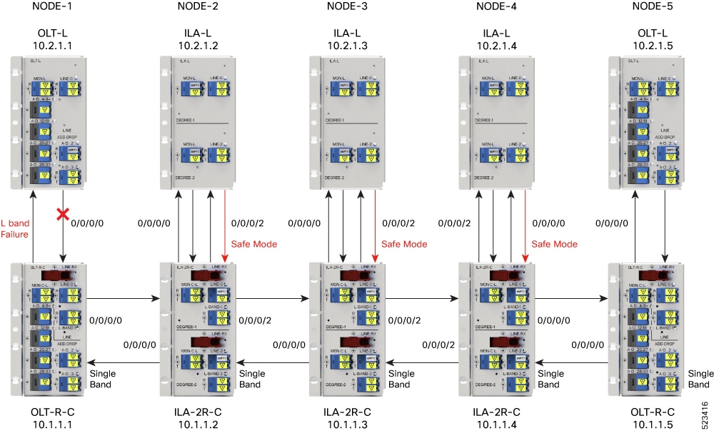
Example
The following example shows the status of BFR when L-band is in the FAILED state. In this case, all the C band nodes are switched to single-band PSD profiles and L band devices are set to safe mode.
RP/0/RP0/CPU0#show olc band-status

Controller              : Ots0/0/0/0
Self-Band               : C-Band
BFR status              : Running

Node RID                : 10.2.1.1
Self IP Address         : 192.0.2.1
Self Controller         : Ots0/0/0/0
Partner IP address      : 192.0.2.2
Partner Controller      : Ots0/0/0/0
Partner link status     : UP
C-Band status           : ACTIVE
C-Band PSD              : Single Band
L-Band status           : FAILED
L-Band PSD              : NA

Node RID                : 10.2.1.2
Self IP Address         : 192.0.2.21
Self Controller         : Ots0/0/0/0
Partner IP address      : 192.0.2.22
Partner Controller      : Ots0/0/0/2
Partner link status     : UP
C-Band status           : ACTIVE
C-Band PSD              : Single Band
L-Band status           : FAILED
L-Band PSD              : NA

Node RID                : 10.2.1.3
Self IP Address         : 192.0.2.31
Self Controller         : Ots0/0/0/0
Partner IP address      : 192.0.2.32
Partner Controller      : Ots0/0/0/2
Partner link status     : UP
C-Band status           : ACTIVE
C-Band PSD              : Single Band
L-Band status           : FAILED
L-Band PSD              : NA

Node RID                : 10.2.1.4
Self IP Address     : 192.0.2.41
Self Controller         : Ots0/0/0/0
Partner IP address      : 192.0.2.42
Partner Controller      : Ots0/0/0/0
Partner link status     : UP
C-Band status           : ACTIVE
C-Band PSD              : Single Band
L-Band status           : FAILED
L-Band PSD              : NA


Node RID                : 10.2.1.5
Self IP Address     : 192.0.2.51
Self Controller         : Ots0/0/0/0
Partner IP address      : 192.0.2.52
Partner Controller      : Ots0/0/0/0
Partner link status     : UP
C-Band status           : ACTIVE
L-Band status           : FAILED
L-Band PSD              : NA
Band Failure Recovery
Once the optical fiber fault is cleared, BFR starts the recovery procedure on all the failed band nodes, one node at a time and also ensures that there is no impact on the traffic. Also, the PSD profiles on the recovered and surviving band are shifted to dual-band PSD profiles.
Note |
|
The following figure illustrates the BFR recovery procedure in case of L-band failure. After the fiber fault is cleared, BFR starts recovery on all C and L-band nodes one node at a time. The recovery procedure on Node 1 is completed and the status is displayed as ACTIVE. The recovery procedure on Node 2 is in progress hence the node status is displayed as RECOVERING. After completing the recovery on Node 2, BFR will start recovery on the remaining nodes one node at a time.
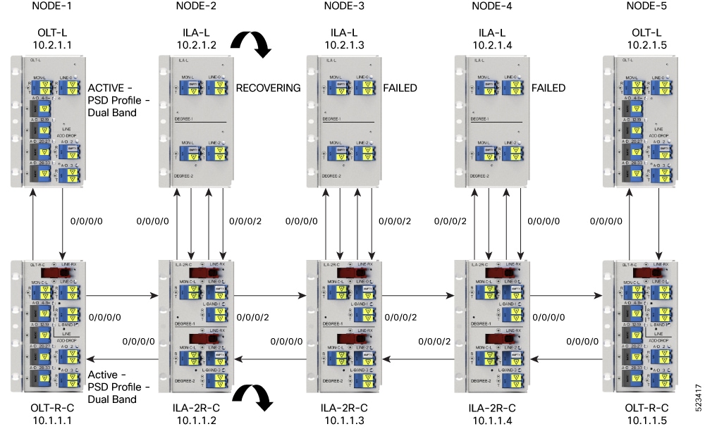
Example
The following example shows status of the C and L-band as RECOVERING on the 192.0.2.1 node:
RP/0/RP0/CPU0:#show olc band-status

Controller              : Ots0/0/0/0
Self-Band               : C-Band
BFR status              : Running

Node RID                : 10.1.1.1
Self IP Address     : 192.0.2.1
Self Controller         : Ots0/0/0/0
Partner IP address      : 192.0.2.2
Partner Controller      : Ots0/0/0/0
Partner link status     : UP
C-Band status           : ACTIVE
C-Band PSD              : Dual Band
L-Band status           : ACTIVE
L-Band PSD              : Dual Band

Node RID                : 10.1.1.2
Self IP Address         : 192.0.2.21
Self Controller         : Ots0/0/0/0
Partner IP address      : 192.0.2.22
Partner Controller      : Ots0/0/0/2
Partner link status     : UP
C-Band status           : RECOVERING
C-Band PSD              : NA
L-Band status           : RECOVERING
L-Band PSD              : NA

Node RID                : 10.1.1.3
Self IP Address         : 192.0.2.31
Self Controller         : Ots0/0/0/0
Partner IP address      : 192.0.2.32
Partner Controller      : Ots0/0/0/2
Partner link status     : UP
C-Band status           : ACTIVE
C-Band PSD              : Single Band
L-Band status           : FAILED
L-Band PSD              : NA

Node RID                : 10.1.1.4
Self IP Address         : 192.0.2.41
Self Controller         : Ots0/0/0/0
Partner IP address      : 192.0.2.42
Partner Controller      : Ots0/0/0/0
Partner link status     : UP
C-Band status           : ACTIVE
C-Band PSD              : Single Band
L-Band status           : FAILED
L-Band PSD              : NA

Node RID                : 10.1.1.5
Self IP Address         : 192.0.2.51
Self Controller         : Ots0/0/0/0
Partner IP address      : 192.0.2.52
Partner Controller      : Ots0/0/0/0
Partner link status     : UP
C-Band status           : ACTIVE
L-Band status           : FAILED
Single Band Failure Recovery on Non-Raman Network
In case of single band failure on a non-Raman network, after the optical fiber fault is cleared, BFR performs the following operations:
-
Starts recovery on the failed band one node at a time.
-
After the recovery is completed and both the bands are active, BFR switches the PSD profiles on both bands to dual-band PSD.
Span Failure Recovery
On a C+L band network, when both bands fail, BFR does not change the PSD profile to single-band PSD. After the failure is cleared, both the bands are recovered quickly.
When a span failure is cleared on a Raman network, in case Raman tuning is disabled, BFR starts the recovery of nodes. When Raman tuning is enabled, BFR suspends recovery and resumes it only after Raman tuning is completed.
Single Band Failure Recovery on a Raman Network
On a C+L band network without Raman amplifiers, when a band fails, Loss of Signal (LOS) is reported because the total power drops below the safe value. This shuts down the amplifiers on other nodes. On a Raman network, if a band fails on the near end node, the amplifiers on the far end nodes receive some band power because of ASE. In this case, LOS is not reported and the amplifiers on far end nodes remain active. BFR ensures that recovery on the far end nodes is started even if the amplifiers on the nodes are active because of ASE and sets safe mode on the failed band.
Once the optical fiber fault is cleared on a Raman network, if Raman tuning is started, BFR suspends recovery and resumes it only after Raman tuning is completed. If Raman tuning is not started, BFR starts the recovery of nodes one by one.
Band Failure Recovery Due to Device in Headless Mode
In case of a band failure on a network that has an OLT device in headless mode:
-
BFR will not switch the PSD profile to single-band PSD.
-
BFR will not run the recovery procedure.
In case of a band failure on a network that has an ILA device in headless mode:
-
BFR switches the PSD profile to single-band PSD on all the nodes that are reachable by C band OLT.
-
BFR does not run the recovery procedure on all the OLT and ILA nodes.
-
If one or more nodes on the network are in headless mode, BFR is not initiated which might affect traffic recovery. In this case, perform the following tasks to restore the traffic:
For more information about these commands, see the Command Reference for Cisco NCS 1010 guide.
Band Failure Recovery Due to Partner Link Status is Down
On a C+L band network, if there is a connectivity failure between the C-band and L-band ILA nodes, BFR does not start the recovery procedure. If the recovery procedure is running and the Partner link status is DOWN, BFR suspends recovery and resumes it only after the Partner link status is UP.
Example
The following example shows the output of the show olc band-status command where the Partner link status status is UP.
RP/0/RP0/CPU0:#show olc band-status

Controller              : Ots0/0/0/0
Self-Band               : C-Band
BFR status              : Running

Node RID                : 10.1.1.1
Self IP Address         : 192.0.2.1
Self Controller         : Ots0/0/0/0
Partner IP address      : 192.0.2.2
Partner Controller      : Ots0/0/0/0
Partner link status     : UP
C-Band status           : ACTIVE
C-Band PSD              : Dual Band
L-Band status           : ACTIVE
L-Band PSD              : Dual Band
Pause and Resume BFR
While recovering from a span failure, if one of the bands is in failed state, BFR is not initiated and the other band is not recovered. In such cases, you can pause, initialize, and resume BFR to initiate it and to bring up the other band.
Pause BFR
Use the following commands to pause BFR:
configure
optical-line-control
controller ots Rack/Slot/Instance/Port
bfr-pause
commit
end
Example
The following is a sample configuration to pause BFR:
RP/0/RP0/CPU0:#configure
RP/0/RP0/CPU0: (config)#optical-line-control
RP/0/RP0/CPU0: (config-olc)#controller ots 0/0/0/0
RP/0/RP0/CPU0: (config-olc-ots)#bfr-pause
RP/0/RP0/CPU0: (config-olc-ots)#commit
Resume BFR
Use the following commands to resume BFR:
configure
optical-line-control
controller ots Rack/Slot/Instance/Port
no bfr-pause
commit
end
Example
The following is a sample configuration to resume BFR:
RP/0/RP0/CPU0:#configure
RP/0/RP0/CPU0: (config)#optical-line-control
RP/0/RP0/CPU0: (config-olc)#controller ots 0/0/0/0
RP/0/RP0/CPU0: (config-olc-ots)#no bfr-pause
RP/0/RP0/CPU0: (config-olc-ots)#commit
For more information about these commands, see bfr-pause in the Command Reference for Cisco NCS 1010 guide.
Note |
To upgrade from R7.9.1 to R7.10.1 or later with BFR pause enabled, before upgrading software, pause BFR on the OLT-C band using the olc bfr pause command before beginning the software upgrade. Once the upgrade is finished, pause and resume BFR using the bfr-pause configuration command on the OLT-C and OLT-L bands. |
 Feedback