Plan Your Network
The following sections describe how to plan an NCS 1010 based network, using Cisco ONP. Cisco ONP helps with designing a topology with the required specifications, analyze it, and generate the planning data.
The documentation set for this product strives to use bias-free language. For the purposes of this documentation set, bias-free is defined as language that does not imply discrimination based on age, disability, gender, racial identity, ethnic identity, sexual orientation, socioeconomic status, and intersectionality. Exceptions may be present in the documentation due to language that is hardcoded in the user interfaces of the product software, language used based on RFP documentation, or language that is used by a referenced third-party product. Learn more about how Cisco is using Inclusive Language.
This document provides instructions on how to deploy an NCS 1010 based network, using Cisco ONP, ZTP, and Cisco ONC. Cisco ONP helps with designing a topology with the required specifications, analyze it, and generate the planning data. ZTP, then sets up and brings up the devices. Cisco ONC uses the planning data from Cisco ONP to configure and manage the devices.
This chapter describes the Design and Analysis of Networks and how to Export Planning data from Cisco Optical Network Planner.
The following sections describe how to plan an NCS 1010 based network, using Cisco ONP. Cisco ONP helps with designing a topology with the required specifications, analyze it, and generate the planning data.
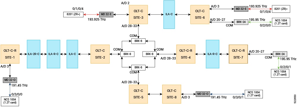
The network topology that is shown in this section has been used to explain the NCS 1010 bring-up scenarios. It is a four-degree topology that uses 13 NCS 1010 nodes. The BRK-8 modules are used to create express interconnects among SITE-2, SITE-3, SITE-4, and SITE-5 using MPO cables.
Use the following steps to design the topology in Cisco ONP:
|
Step 1 |
Log in to Cisco ONP Web Interface. |
|
Step 2 |
Choose . The Create New Network dialog box appears. |
|
Step 3 |
From the L0 Network Platform drop-down list, choose NCS1010. |
|
Step 4 |
Click Create. You can view the map and the design palette. |
|
Step 5 |
Click the Drawing Tool icon (pencil and ruler crossed). |
|
Step 6 |
Add sites to the map using the drawing tool. |
|
Step 7 |
Set the properties of OLA nodes added in the topology to convert them into ILA- C, ILA-R-C, or ILA-2R-C nodes. |
|
Step 8 |
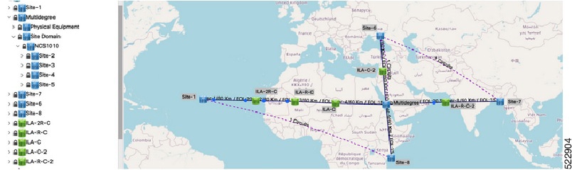
Create circuits between Site-6 to Site-7, Multidegree Site to Site 6, and Site 1 to Site 8.
|
|
Step 9 |
To add the MD-32-E and MD-32-O Mux/Demux patch panels, set the following properties:
|
|
Step 10 |
To add BRK-24 and BRK-8 breakout panels, set the following properties:
|
|
Step 11 |
To add NCS 1004 (1.2T card), set the following properties:
|
|
Step 12 |
To add 8201 (ZR+) pluggable, set the following properties:
|
|
Step 13 |
Choose . |
|
Step 14 |
Enter a network name in the Give a Network Name dialog box. |
|
Step 15 |
Click Save. |
Analyze the designed sample network to check the feasibility of the network using the following steps:
|
Step 1 |
Log in to Cisco ONP Web Interface. |
|
Step 2 |
Choose . The Select Network To Open dialog box appears. |
|
Step 3 |
Click the sample topology network that you have created, from the list of networks. |
|
Step 4 |
Choose . The Cisco ONP analysis progress indicator indicates the analysis status. If there is any failure in the analysis stage, a pop-up window appears with the message, “Analysis Failed.” |
|
Step 5 |
Choose the tab to see the list of error details in the analyzed network. By default, it shows only the key messages when the Critical Only toggle button is enabled. If you want to view the entire network message, disable the Critical Only toggle button. |
|
Step 6 |
If you find an error message under the Messages tab, resolve the error and analyze the network again. Repeat this step until all errors are resolved. |
Export the network planning data which is in the form of JSON file from Cisco ONP using the following steps. This JSON file is uploaded into Cisco ONC to configure the managed devices.
|
Step 1 |
Log in to Cisco ONP Web Interface. |
|
Step 2 |
Choose . The Select Network To Open dialog box appears. |
|
Step 3 |
In the network tree panel, right-click the network name. |
|
Step 4 |
Click Generate CONC JSON. |
|
Step 5 |
In the Export File dialog box, enter the name of the JSON file. |
|
Step 6 |
Click Export to download the JSON file into your local system. |
 Feedback