The documentation set for this product strives to use bias-free language. For the purposes of this documentation set, bias-free is defined as language that does not imply discrimination based on age, disability, gender, racial identity, ethnic identity, sexual orientation, socioeconomic status, and intersectionality. Exceptions may be present in the documentation due to language that is hardcoded in the user interfaces of the product software, language used based on RFP documentation, or language that is used by a referenced third-party product. Learn more about how Cisco is using Inclusive Language.
The following list contains the pre-requisites of Cisco Optical Network Controller 3.1 installation.
Before installing Cisco Optical Network Controller 3.1, you must first login in to the VMware customer center and download VMware vCenter server version 7.0, as well as vSphere
server and client with version 7.0. Cisco Optical Network Controller 3.1 is deployed on rack or blade servers within vSphere.
ESXi host must be installed on servers with vSphere version of 6.7.0 or 7.0 to support creating Virtual Machines (VM).
Before the Cisco Optical Network Controller 3.1 installation, two networks are required to be created.
Control Plane Network:
The control plane network helps in the internal communication between the deployed VMs within a cluster. If you are setting
up a standalone system, this can refer to any private network. However, in case of a High Availability (HA) cluster, this
network is created between the servers where each node of the HA cluster is being created.
VM Network or Northbound Network:
The VM network is used for communication between the user and the cluster. It handles all the traffic to and from the VMs
running on your ESXi hosts and this is your Public network through which the UI is hosted.
Note
For more details on VMware vSphere, see VMware vSphere.
The minimum requirement for Cisco Optical Network Controller 3.1 installation is given in the table below.
Table 1. Minimum Requirement
Sizing
CPU
Memory
Disk
XS
12 vCPU
52 GB
200
S
30 vCPU
100 GB
300
The requirements based on type of deployment are given in the table below.
Table 2. Deployment Requirements
Deployment Type
Requirements
Standalone ( SA )
Control Plane: 1 IP ( this can be a private network).
Northbound Network/VM Network: 1 IP (this must be a public network)
Highly Available ( HA )
Control Plane: 3 IPs (this can be a private network) - IPs required for individual nodes.
VM Network: 4 IPs ( this must be a public network) with 3 IPs for node management and 1 IP for Virtual IP, which is used for northbound
communication and UI.
Note
For a High Availability (HA) deployment, nodes on different ESXi hosts should have a minimum link bandwidth of 10G between
them. This is recommended to ensure efficient data communication and synchronization between the nodes.
To create the control plane and virtual management networks follow the steps listed below.
From the vSphere client select the Datacenter where you want to add the ESXi host.
After adding the ESXi host create the Control Plane and VM Networks before deploying the SA or HA. The HA has four IPs where
one is the primary and the others can join as secondary and tertiary IP addresses. The SA has only one IP. Also, in the case
of HA the Virtual IP is the IP that exposes the active node to the user.
SSH Key Generation
For accessing SSH, ed25519 key is required. The ed25519 key is different from the RSA key.
Use the CLI given below to generate the ed25519 key.
ssh-keygen -t ed25519
Generating public/private ed25519 key pair.
Enter file in which to save the key (/Users/xyz/.ssh/id_ed25519): ./<file-name-of-your-key>.pem
Enter passphrase (empty for no passphrase):
Enter same passphrase again:
Your identification has been saved in ./<file-name-of-your-key>.pem
Your public key has been saved in ./<file-name-of-your-key>.pem.pub
The key fingerprint is:
SHA256:zGW6aGn8rxvEq82sA/97jOaHrl9rnoTaYi+TqU3MeRU xyz@abc
The key's randomart image is:
+--[ED25519 256]--+
|                 |
|                 |
|          E      |
|       + + .     |
|        S .      |
|    .+ = =       |
|     o@o*+o      |
|     =XX++=o     |
|    .o*#/X=      |
+----[SHA256]-----+

#Once created you can cat the file with .pub extension for the public key. ( ex: <file-name-of-your-key>.pem.pub )

cat <file-name-of-your-key>.pem.pub
#The above key has to be used in the deployment template ( SSH Public Key ) in the Deployment process
Installation
To deploy the OVA template. Follow the steps given below.
Before you begin
Note
During the OVF deployment, the deployment gets aborted if there is an internet disconnection.
Procedure
Step 1
Right click the ESXi host in the vSphere client screen and click Deploy OVF Template.
Step 2
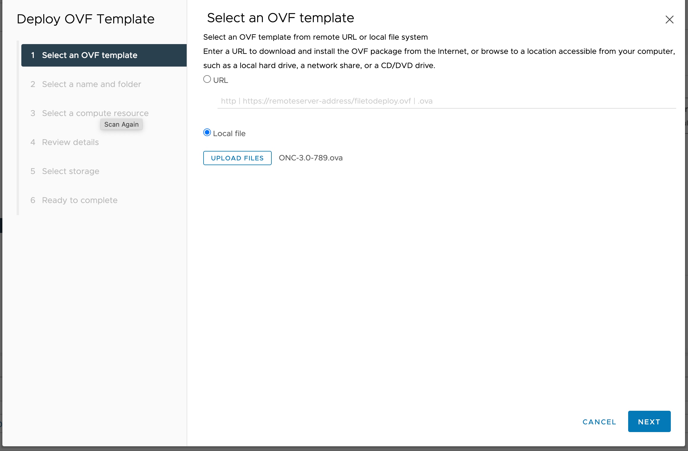
In the Select an OVF template screen, select the URL radio button for specifying the online link or select the Local file radio button to upload the downloaded ova files from your local system and click Next.
Figure 1. Select an OVF Template
Step 3
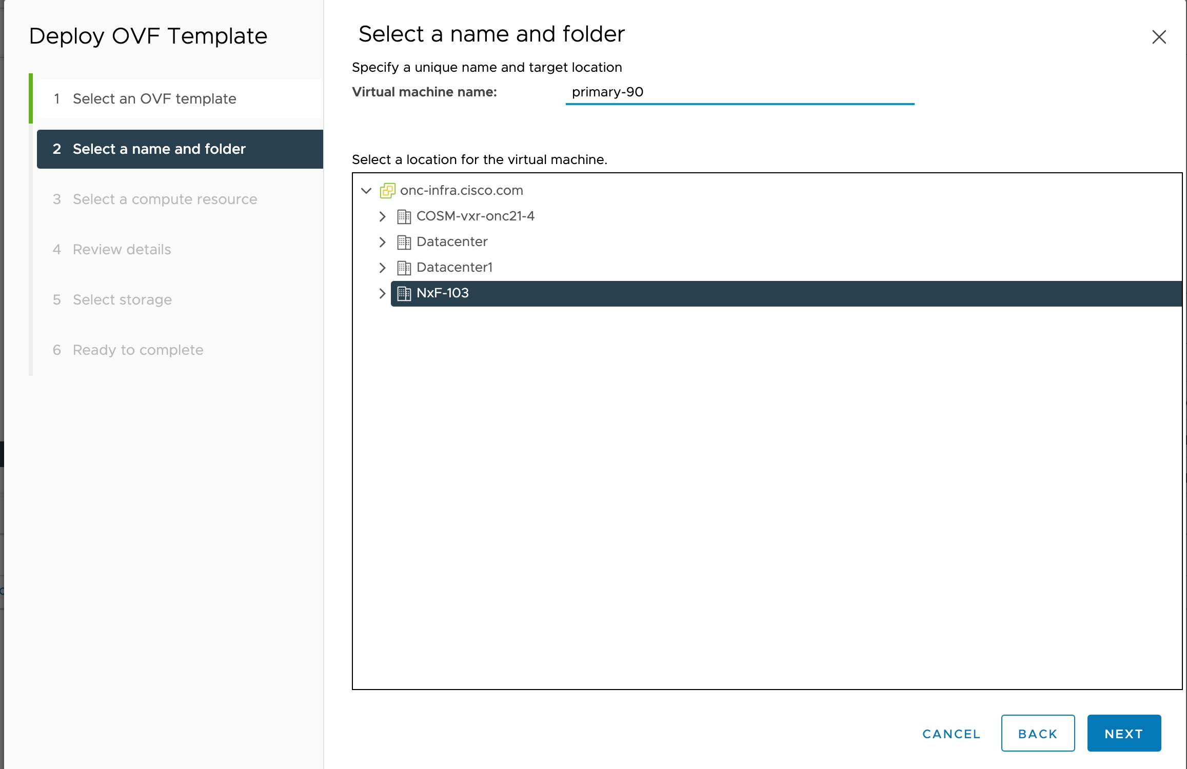
In the Select a name and folder screen, specify a unique name for the virtual machine Instance. Cisco Optical Network Controller can be deployed as Standalone
or High Availability. From the list of options, select the location of the VM to be used as Standalone or High Availability
(primary, secondary, or tertiary) and click Next.
Figure 2. Select a name and folder
Step 4
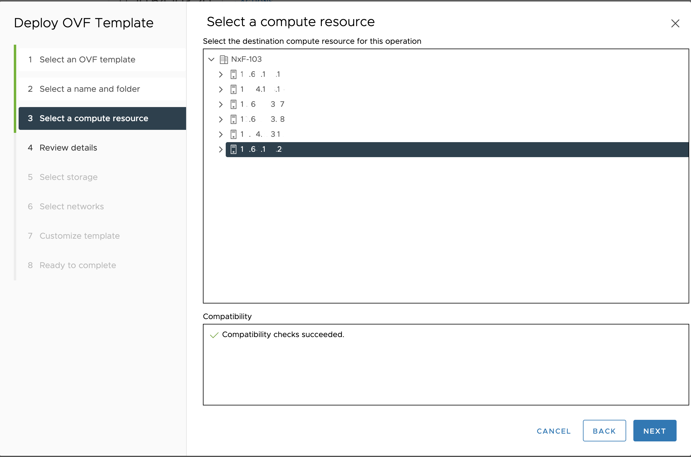
In the Select a compute resource screen, select the destination compute resource on which you want to deploy the VM and click Next.
Figure 3. Select a Compute Resource
Note: While selecting the compute resource the compatibility check proceeds till it completes successfully.
Step 5
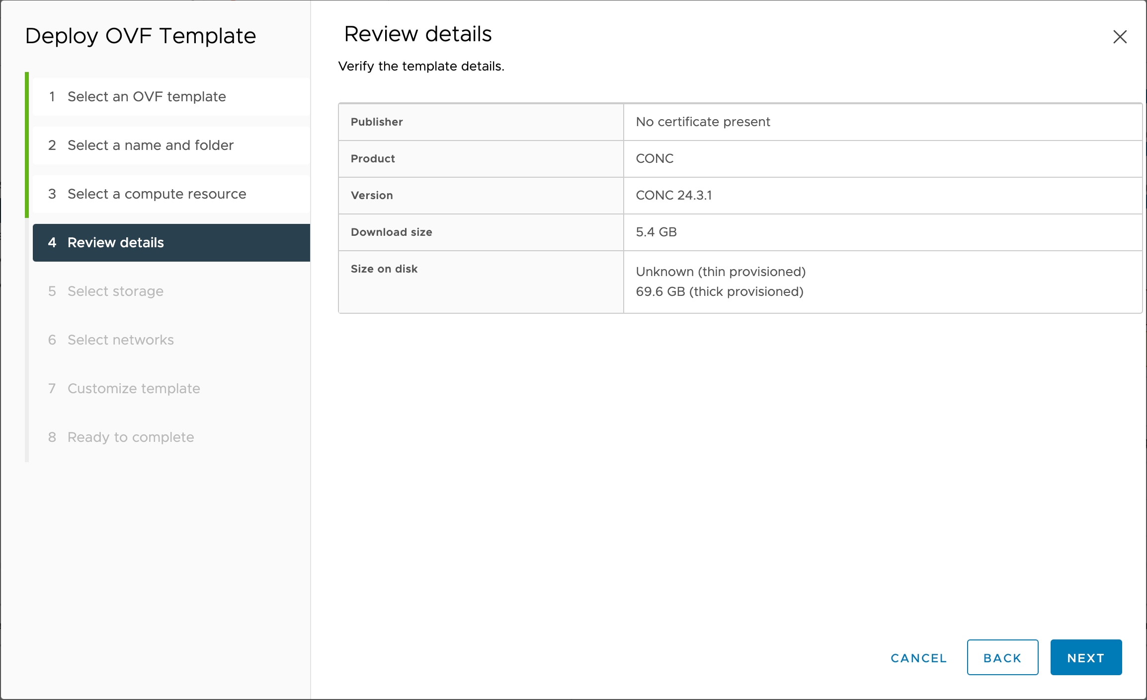
In the Review details screen, verify the template details and click Next.
Figure 4. Review Details
Step 6
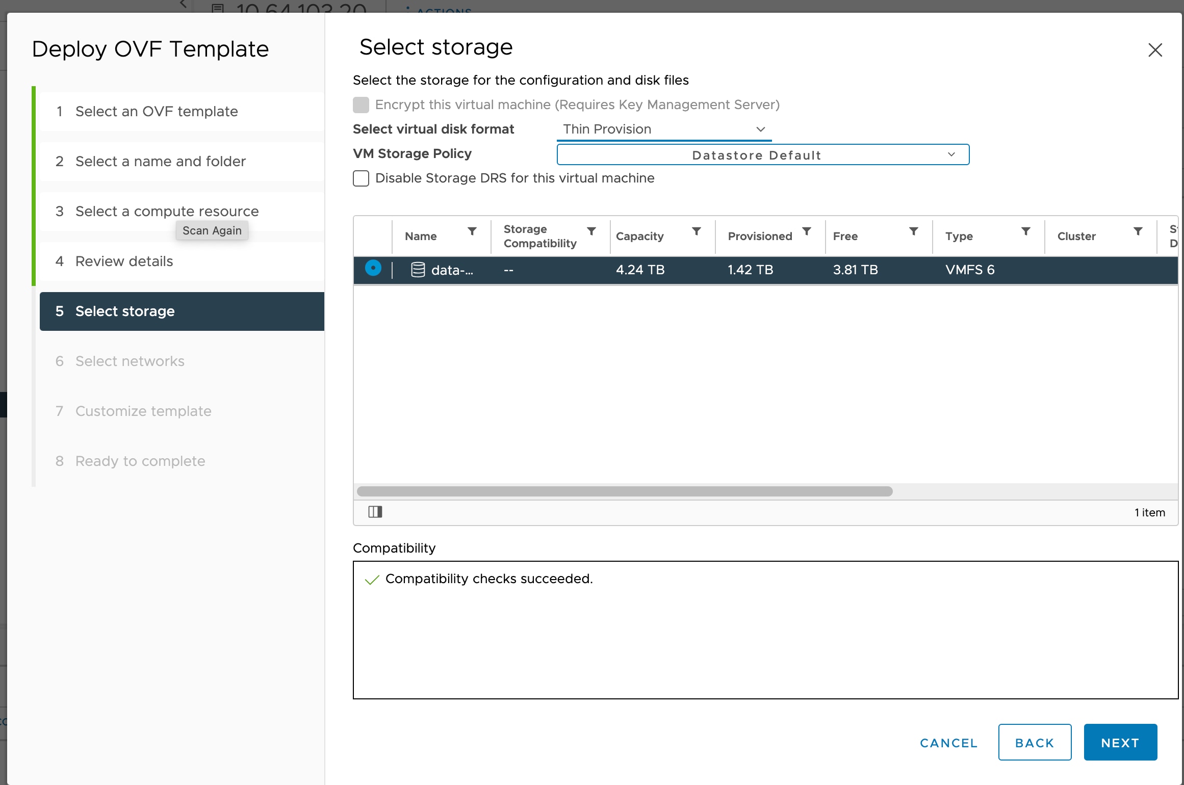
In the Select storage screen, select the virtual disk format based on provision type requirement. VM Storage Policy is set as Datastore Default and click Next. Select the virtual disk format as Thin Provision.
the selection should be "Thin provisioning"
Figure 5. Select Storage
Step 7
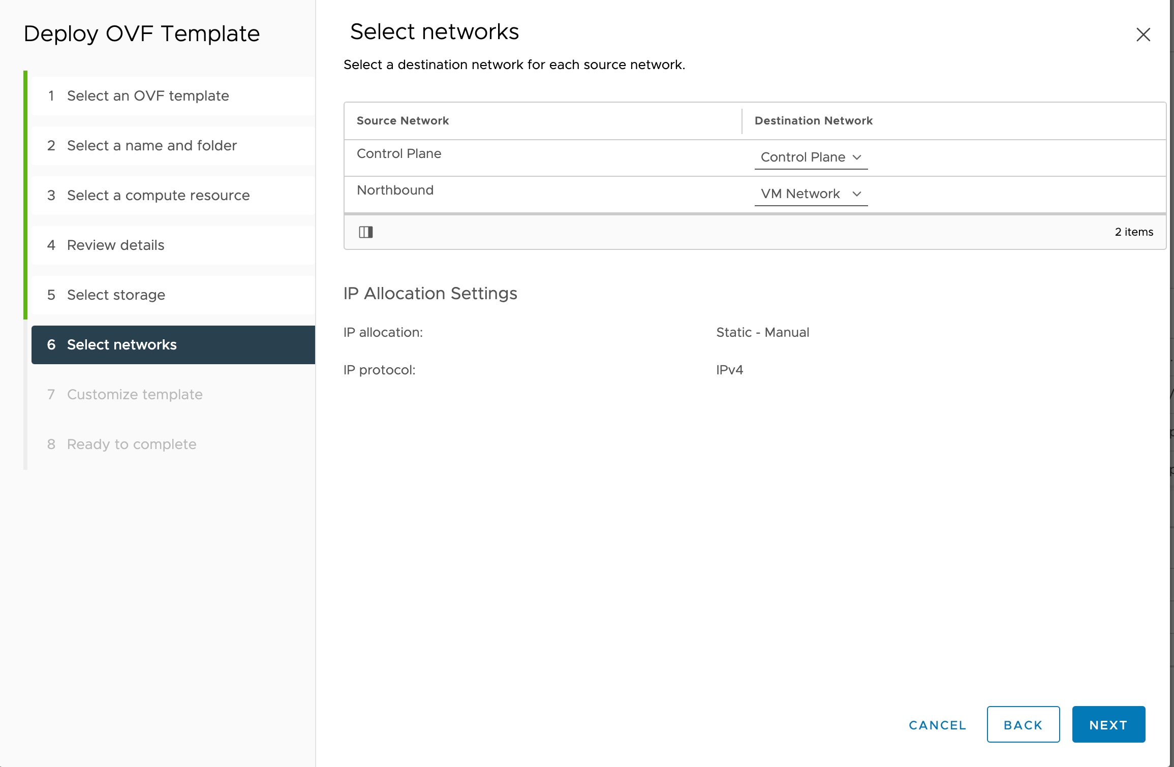
In the Select networks screen, select the control and management networks as Control Plane and VM Network from the networks created earlier and click Next.
Figure 6. Select Networks
Step 8
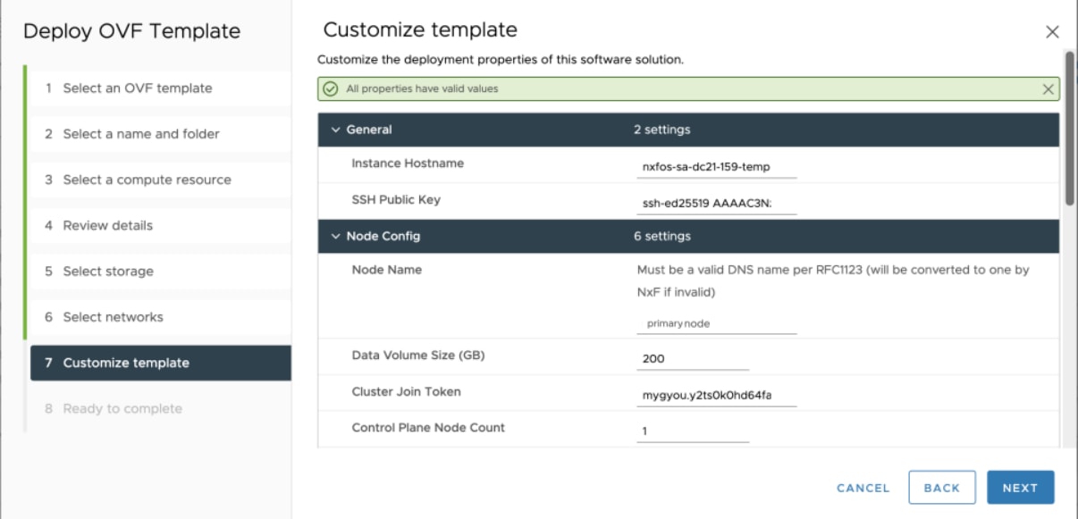
In the Customize template screen, set the values using the following table as a guideline for deployment.
Figure 7. Customize Template
Table 3. Customize Template
Key
Values
Instance Hostname
<instance hostname>
SSH Public Key
<ssh-public-key>. Used for SSH access that allows you to connect to the instances securely without the need to manage credentials for multiple
instances. SSH public key must be a ed25519 key.
Node Name
<primary/secondary/tertiary>
Must be a valid DNS name per RFC1123.1.2..4
Contain at most 63 characters.
Contain only lowercase alphanumeric characters or '-'.3
Start with an alphanumeric character.
End with an alphanumeric character. Standalone: primary, High Availability: primary, secondary or tertiary in accordance with
the node role.
Data Volume Size (GB)
<recommended-size> The data storage limit is set for the host with 200GB is as minimum value.
Cluster Join Token
<token-value> This is a pre-filled value.
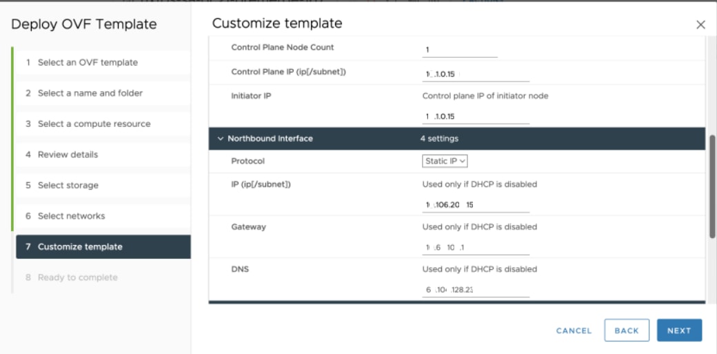
Control Plane Node Count
<CP-node-count> One for Standalone and three for High Availability.
Control Plane IP
<ip/subnet> It is the private IP for the instance which is the dedicated control plane IP for this node from the control plane network.
Note
Subnet is a mandatory field amd must be specified in the template.
Initiator IP
<> Initiator IP should be matching the control plane IP of the node , which is marked as the initiator node as part of this
template. We recommend using primary node as the Initiator node and use the control plane IP of the primary node.
Standalone: Same as the control plane IP.
High Availability: control plane IP of the primary node in all three repetition of the deployment.
Protocol
Static or DHCP IP address.
IP (IP[/subnet]) - if not using DHCP
<ip/subnet> It is the public IP for the instance in Northbound Network. This IP is used for managing the node and comes from
the Northbound network or VM network. It can be used for SSH to the particular node. In case of High Availability, three distinct
IP addresses are used.
Note
Subnet is a mandatory field and must be specified in the template.
Gateway - if not using DHCP
<gateway-ip for the instance> Northbound Network.
DNS
DNS Server IP. A valid DNS accessible from the network is required.
Initiator Node
This node is set to ‘True’ by checking it for the control plane IP. In case of Standalone, it is set as 'True' for the control
plane IP of the single node. In case of high availability it is set to 'True' by checking it only for the Initiator node,
which is the primary node for the Control Plane IP, similar to Standalone.
Northbound Virtual IP
<IP> It is same as public IP for the Instance for the Northbound Network. It is used for all the northbound connections, such
as UI and RESTCONF.
For Standalone this IP is the same as the Northbound Network/VM Network IP of the primary node. For High Availability, we
recommend using a distinct IP from Northbound Network/VM Network and must be the same for all 3 nodes.
Primary Node Name
It is a string and is the name of the primary node. It must remain the same all the three times in case of High Availability.
Use the node name that you chose for the primary node in node config.
Secondary Node Name
It is a string and is the name of the secondary node. Use the node name that you chose for the secondary node in node config.
Tertiary Node Name
It is a string and is the name of the tertiary node. Use the node name that you chose for the tertiary node in node config.
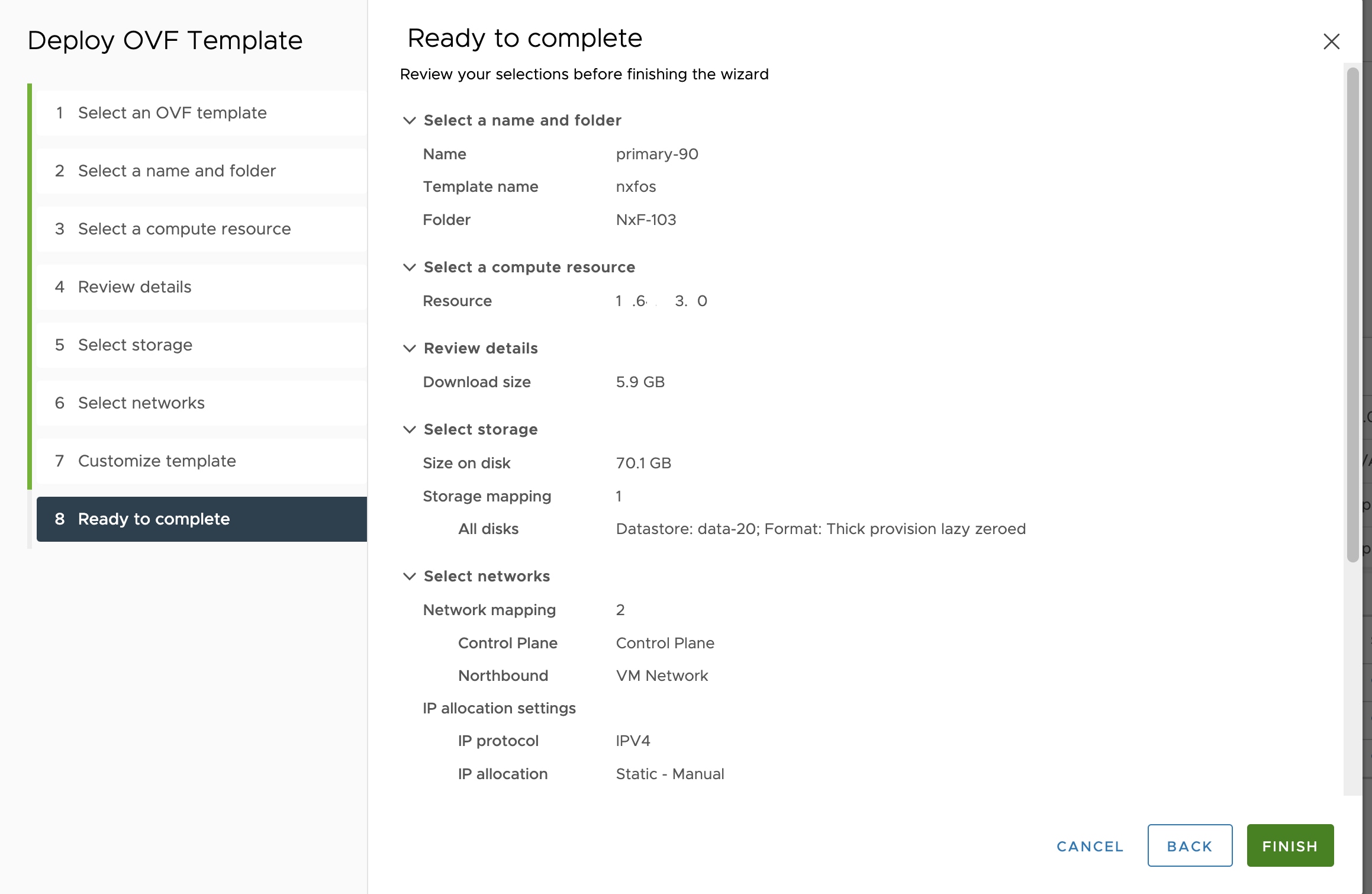
Step 9
In Review the details screen, review all your selections and click Finish. To check or change any properties from the review screen anytime, before clicking Finish click BACK to go back to the previous screen Customize template to ad your changes.
Figure 8. Ready to Complete
Step 10
Using the steps above from step 1 to 8, you can create one VM for Standalone and three VMs for High Availability. In case
of High Availability, it is recommended to create all three VMs (primary/secondary/tertiary) before they are turned ON.
Attention
Upon activation of the virtual machine (VM), it is designed not to respond to ping requests. However, you can log in using
SSH if the installation has been completed successfully.
Step 11
After the VM is created, try connecting to the VM using the pem key which was generated earlier, see SSH Key Generation above. For this, use the private key that is generated along with the public key during customizing the public key options.
Step 12
Log in to the VM using the private key.
Note:
After the nodes are deployed, the deployment of OVA progress can be checked in the Tasks console of vSphere Client. After
Successful deployment CONC takes around 30 minutes to boot.
The user-id by default is the admin user id and only the password is needed to be set.
Step 13
SSH to the node and execute the following CLI command.
##Command to have change permission of key
chmod 400 <file-name-of-your-key>.pem

ssh -i [ed25519 Private key] nxf@[primary, secondary, tertiary]
Enter passphrase for key '<file-name-of-your-key>.pem':
Note
Private key is created as part of the key generation with just the .pem extension, and it must be set with the least permission level before using it.
Step 14
When the SSH to node completes use the following command to check the ready status of CONC.
Note: Services can take up to 30 minutes to boot.
Step 15
Use the sedo system status command to check the status of all the pods as seen below.
#Command
sedo system status

#Example Output
┌──────────────────────────────────────────────────────────────────────────────────────┐
│ System Status (Mon, 26 Feb 2024 07:34:48 UTC)                                        │
├────────┬──────────────────────────────┬───────────┬─────────┬──────────┬─────────────┤
│ OWNER  │ NAME                         │ ZONE/NODE │ STATUS  │ RESTARTS │ STARTED     │
├────────┼──────────────────────────────┼───────────┼─────────┼──────────┼─────────────┤
│ system │ authenticator                │ primary   │ Running │ 0        │ 3 weeks ago │
│ system │ controller                   │ primary   │ Running │ 0        │ 3 weeks ago │
│ system │ ingress-proxy                │ primary   │ Running │ 0        │ 3 weeks ago │
│ system │ kafka                        │ primary   │ Running │ 0        │ 3 weeks ago │
│ system │ loki                         │ primary   │ Running │ 0        │ 3 weeks ago │
│ system │ metrics                      │ primary   │ Running │ 0        │ 3 weeks ago │
│ system │ minio                        │ primary   │ Running │ 0        │ 3 weeks ago │
│ system │ postgres                     │ primary   │ Running │ 0        │ 3 weeks ago │
│ system │ promtail-fg6ws               │ primary   │ Running │ 0        │ 3 weeks ago │
│ system │ registry                     │ primary   │ Running │ 0        │ 3 weeks ago │
│ system │ vip-add                      │ primary   │ Running │ 0        │ 3 weeks ago │
│ onc    │ monitoring                   │ primary   │ Running │ 0        │ 6 days ago  │
│ onc    │ onc-alarm-service            │ primary   │ Running │ 0        │ 3 weeks ago │
│ onc    │ onc-apps-ui                  │ primary   │ Running │ 0        │ 3 weeks ago │
│ onc    │ onc-circuit-service          │ primary   │ Running │ 0        │ 3 weeks ago │
│ onc    │ onc-collector-service        │ primary   │ Running │ 0        │ 3 weeks ago │
│ onc    │ onc-config-service           │ primary   │ Running │ 0        │ 3 weeks ago │
│ onc    │ onc-deployer-service         │ primary   │ Running │ 0        │ 3 weeks ago │
│ onc    │ onc-deployerengine-service   │ primary   │ Running │ 0        │ 3 weeks ago │
│ onc    │ onc-devicemanager-service    │ primary   │ Running │ 0        │ 3 weeks ago │
│ onc    │ onc-inventory-service        │ primary   │ Running │ 0        │ 3 weeks ago │
│ onc    │ onc-nbi-service              │ primary   │ Running │ 0        │ 3 weeks ago │
│ onc    │ onc-netconfcollector-service │ primary   │ Running │ 0        │ 3 weeks ago │
│ onc    │ onc-osapi-gw-service         │ primary   │ Running │ 0        │ 3 weeks ago │
│ onc    │ onc-pce-service              │ primary   │ Running │ 0        │ 3 weeks ago │
│ onc    │ onc-pm-service               │ primary   │ Running │ 0        │ 3 weeks ago │
│ onc    │ onc-pmcollector-service      │ primary   │ Running │ 0        │ 3 weeks ago │
│ onc    │ onc-topology-service         │ primary   │ Running │ 0        │ 3 weeks ago │
│ onc    │ onc-torch-service            │ primary   │ Running │ 0        │ 3 weeks ago │
└────────┴──────────────────────────────┴───────────┴─────────┴──────────┴─────────────┘
Note
The different pods along with their statuses including active and standby modes are all displayed in the different terminal
sessions for each pod.
All the services with owner onc must display the status as Running.
Step 16
Use the following CLI command to check and verify which node is active.
Use the following CLI command to check and verify whether all nodes have joined the cluster or not.
root@vc39-es20-ha-171-primary:~# kubectl get nodes
NAME        STATUS   ROLES           AGE     VERSION
primary     Ready    control-plane   5d15h   v1.28.5
secondary   Ready    control-plane   5d15h   v1.28.5
tertiary    Ready    control-plane   5d15h   v1.28.5
Note
The steps 16 and 17 above are for High Availability installation.
Step 18
SSH to the node and set the initial UI password for the admin user.
For both Standalone and High Availability, execute the following command on any of the nodes.
sedo security user set admin --password
Step 19
Set up the Network Time Protocol (NTP) command to set the NTP server configuration on all the hosts using the following commands.
 vi /etc/chrony.conf
server IP/DNS iburst
# Apply the new ntp setting
systemctl restart chronyd
## To Check the Server
chronyc sources
Note
You must perform NTP configuration as a superuser.
In case of High Availability, the following steps must be executed in all the three nodes.
Step 20
You can check the current version using the sedo version command on the SSH of the VM.
Step 21
The default admin user id can be checked by using the sedo security user list command and the default password can be changed using the sedo command sedo security user admin set --password on the CLI console of the VM or through web UI both.
Step 22
Check the servicepack status, sedo service list-installed on the SSH of the VM.
#Enable Password Login
sudo vi /etc/ssh/sshd_config


##Add the following Configs
PermitRootLogin Yes
PasswordAuthentication yes


systemctl restart sshd
passwd root ##It promts you to enter the password
Step 23
Cisco Optical Network Controller 3.1 WebUI can be used for browsing using the IP addresses. In case of Standalone, the Standalone IP address is used in the URL
and in case of High Availability the Virtual IP (VIP) addresses are used in the URL as given here: https://<virtual ip>:8443/
Step 24
Once the setup steps given above are completed successfully, the Cisco Optical Network Controller 3.1 devices page appears on the screen. Use the admin id and the password to access the installed Cisco Optical Network Controller
3.1.
Note
For High Availability deployments, you must set the NETCONF Session Timeout Configuration to no-timeout on COSM before they are onboarded to Cisco ONC.
To configure NETCONF Session Timeout Configuration in COSM, follow the instructions at Configure Netconf and Nodal Craft Session Timeout. Go to: https://<Cisco-Optical-Site-Manager-IP>/#/usersConfiguration?tab=General


 Feedback