Segment Routing Configuration Guide for Cisco NCS 560 Series Routers, IOS XR Release 24.1.x, 24.2.x, 24.3.x
Bias-Free Language
The documentation set for this product strives to use bias-free language. For the purposes of this documentation set, bias-free is defined as language that does not imply discrimination based on age, disability, gender, racial identity, ethnic identity, sexual orientation, socioeconomic status, and intersectionality. Exceptions may be present in the documentation due to language that is hardcoded in the user interfaces of the product software, language used based on RFP documentation, or language that is used by a referenced third-party product. Learn more about how Cisco is using Inclusive Language.
Tree Segment Identifier (Tree-SID) is an SDN controller-based approach to build label switched multicast (LSM) Trees for efficient
delivery of multicast traffic in an SR domain and without the need for multicast protocol running in the network. With Tree
SID, trees are centrally computed and controlled by a path computation element (SR-PCE).
A Replication segment (as specified in IETF draft "SR Replication segment for Multi-point Service Delivery") is a type of segment which allows a node (Replication node) to replicate packets to a set of other nodes (Downstream nodes)
in a Segment Routing Domain.
A Replication segment includes the following:
Replication SID: The Segment Identifier of a Replication segment. This is an SR-MPLS label (Tree SID label).
Downstream nodes: Set of nodes in Segment Routing domain to which a packet is replicated by the Replication segment.
A Point-to-Multipoint (P2MP) tree is formed by stitching Replication segments on the Root node, intermediate Replication nodes,
and Leaf nodes. This is referred to as an SR P2MP Policy (as specified in IETF draft "Segment Routing Point-to-Multipoint Policy").
An SR P2MP policy works on existing MPLS data-plane and supports TE capabilities and single/multi routing domains. At each
node of the tree, the forwarding state is represented by the same Replication segment (using a global Tree-SID specified from
the SRLB range of labels).
An SR P2MP policy request contains the following:
Policy name
SID for the P2MP Tree (Tree-SID)
Address of the root node
Addresses of the leaf nodes
Optimization objectives (TE, IGP metric)
Constraints (affinity)
The SR-PCE is responsible for the following:
Learning the network topology - to be added
Learning the Root and Leaves of a Tree - describe dynamic and static Tree SIDs (16-17) - Tree SID Policy Types and Behaviors
Computing the Tree
Allocating MPLS label for the Tree
Signaling Tree forwarding state to the routers
Re-optimizing Tree
Tree SID Policy Types and Behaviors
Static P2MP Policies—can be configured in the following ways:
Tree SID parameters provided via Cisco Crosswork Optimization Engine (COE) UI
COE passes the policy configuration to the SR-PCE via REST API (no Tree-SID CLI at PCE). This method allows for SR-PCE High
Availability (HA).
Tree SID parameters configured via Tree-SID CLI at the SR-PCE
Caution
With this method, SR-PCE HA is not supported. For this reason, this configuration method is not recommended.
Dynamic P2MP Policies—can be configured in the following ways:
A BGP mVPN is configured in the network (PE nodes) – service configuration via CLI or Cisco NSO
As a result, BGP control plane is used for PE auto-discovery and customer multicast signaling.
Tree SID parameters are provided by mVPN PEs via PCEP to the PCE. This method allows for SR-PCE High Availability (HA).
Tree SID Workflow Overview
This sections shows a basic workflow using a static Tree SID policy:
User creates a static Tree-SID policy, either via Crosswork Optimization Engine (preferred), or via CLI at the SR-PCE (not
recommended).
SR-PCE computes the P2MP Tree.
SR-PCE instantiates the Tree-SID state at each node in the tree.
The Root node encapsulates the multicast traffic, replicates it, and forwards it to the Transit nodes.
The Transit nodes replicate the multicast traffic and forward it to the Leaf nodes.
The Leaf nodes decapsulate the multicast traffic and forward it to the multicast receivers.
Bud Node Support
In a multicast distribution tree, a Bud node is a node that acts as a leaf (egress) node as well as a mid-point (transit)
node toward the downstream sub-tree.
In the below multicast distribution tree topology with Root node {A} and Leaf nodes set {B, C, D}, node D is a Bud node. Similarly,
if node E is later added to the Leaf set, it would also become a Bud node.
The tree computation algorithm on SR-PCE has been enhanced to detect a Bud node based on knowledge of the Leaf set, and to
handle Leaf/Transit node transitions to Bud node. The role of the Bud node is also explicitly signaled in PCEP.
Configure Static Segment Routing Tree-SID via CLI at SR-PCE
Caution
With this configuration method, SR-PCE HA is not supported. For this reason, this configuration method is not recommended.
To configure static Segment Routing Tree-SID for Point-to-Multipoint (P2MP) SR policies, complete the following configurations:
Configure Path Computation Element Protocol (PCEP) Path Computation Client (PCC) on all nodes involved in the Tree-SID path
(root, mid-point, leaf)
Configure Affinity Maps on the SR-PCE
Configure P2MP SR Policy on SR-PCE
Configure Multicast on the Root and Leaf Nodes
Configure PCEP PCC on All Nodes in Tree-SID Path
Configure all nodes involved in the Tree-SID path (root, mid-point, leaf) as PCEP PCC. For detailed PCEP PCC configuration
information, see Configure the Head-End Router as PCEP PCC.
Configure Affinity Maps on the SR-PCE
Use the affinity bit-mapCOLORbit-position command in PCE SR-TE sub-mode to define affinity maps. The bit-position range is from 0 to 255.
Use the policypolicy command to configure the P2MP policy name and enter P2MP Policy sub-mode. Configure the source address, endpoint-set color,
Tree-SID label, affinity constraints, and metric type.
Router(config-pce-sr-te-p2mp)# policy FOO
Router(config-pce-p2mp-policy)# source ipv4 10.1.1.6
Router(config-pce-p2mp-policy)# color 10 endpoint-set BAR
Router(config-pce-p2mp-policy)# treesid mpls 15200
Router(config-pce-p2mp-policy)# candidate-paths
Router(config-pce-p2mp-policy-path)# constraints
Router(config-pce-p2mp-path-const)# affinity
Router(config-pce-p2mp-path-affinity)# exclude BLUE
Router(config-pce-p2mp-path-affinity)# exit
Router(config-pce-p2mp-path-const)# exit
Router(config-pce-p2mp-policy-path)# preference 100
Router(config-pce-p2mp-policy-path-preference)# dynamic
Router(config-pce-p2mp-path-info)# metric type te
Router(config-pce-p2mp-path-info)# root
Router(config)#
Configure Multicast on the Root and Leaf Nodes
On the root node of the SR P2MP segment, use the router pim command to enter Protocol Independent Multicast (PIM) configuration mode to statically steer multicast flows into an SR P2MP
policy.
Note
Enter this configuration only on an SR P2MP segment. Multicast traffic cannot be steered into a P2P policy.
On the root and leaf nodes of the SR P2MP tree, use the mdt static segment-routing command to configure the multicast distribution tree (MDT) core as Tree-SID from the multicast VRF configuration submode.
On the leaf nodes of an SR P2MP segment, use the static sr-policy p2mp-policy command to configure the static SR P2MP Policy from the multicast VRF configuration submode to statically decapsulate multicast
flows.
With this feature, you can use SR and MVPN for optimally transporting IP VPN multicast traffic over the SP network, using
SR-PCE as a controller.
With SR’s minimal source router configuration requirement, its ability to implement policies with specific optimization objectives
and constraints, protect against network failures using TI-LFA FRR mechanism, and use SR-PCE to dynamically generate optimal
multicast trees (including when topology changes occur in the multicast tree), the SR-enabled SP network can transport IP
multicast traffic efficiently.
Prerequisites for Multicast VPN: Tree-SID MVPN With TI-LFA
The underlay OSPF/IS-IS network is configured, and OSPF/IS-IS adjacency is formed between routers, across the network.
BGP is configured for the network, and BGP adjacency is formed between routers. BGP MVPN configuration information is provided
in this feature document.
To understand the benefits, know-how, and configuration of SR and SR-TE policies, see About Segment Routing and Configure
SR-TE Policies.
Information About Multicast VPN: Tree-SID MVPN With TI-LFA
Typically, a customer’s IP VPN is spread across VPN sites. IP VPN customer traffic is sent from one site to another over a
VPN Service Provider (SP) network.
When IP multicast traffic within a (BGP/MPLS) IP VPN is transported over an SP network (say, from VPN1-Site-A to VPN1-Site-B, as shown in the image), the SP network requires protocols and procedures to optimally transport multicast traffic from a
multicast sender in Site-A to multicast receivers in Site-B.
This use case explains how to enable SR multicast for an SP network, and efficiently transport IP VPN multicast traffic (sent
from VPN1-Site-A and) received at PE router A, through to PE routers D and E, towards receivers in sites VPN1-Site-B and VPN1-Site-C.
Figure 1. IP VPN Multicast Traffic Flow Over An SP Network
To enable the Multicast VPN: Tree-SID MVPN With TI-LFA feature, the following protocols and software applications are used.
OSPF/IS-IS - The underlay network is created with OSPF/IS-IS routing protocol, and reachability is established across the network. See
Configure Segment Routing for IS-IS Protocolor Configure Segment Routing for OSPF Protocol chapter for details.
BGP Multicast VPN (MVPN) – The PE routers (A, D, and E) are IP VPN end-points for IP multicast traffic arriving at the SP network (at PE router A)
and exiting the SP network (at PE routers D and E). So, BGP MVPN is enabled on the PE routers. NSO is used to configure BGP
MVPN on the PE routers.
BGP Auto-Discovery (AD) - To enable distributed VPN end-point discovery and C-multicast flow mapping and signalling, BGP AD function is configured
on the PE routers. A BGP Auto-Discovery route contains multicast router (loopback IP address) and tree identity (segment ID)
information. It carries the information in the Provider Multicast Service Interface (PMSI) Tunnel Attribute (PTA).
C-multicast states are signaled using BGP.
SR - To transport IP multicast traffic between the VPN end-points (PE routers A, D, and E), Provider (or P-) tunnels are used.
In a P-tunnel, the PE devices are the tunnel end-points. P-tunnels can be generated using different technologies (RSVP-TE,
P2MP LSPs, PIM trees, mLDP P2MP LSPs, and mLDP MP2MP LSPs). In this use case, Segment Routing (SR) is used for its benefits
that were noted earlier.
With SR and SR-PCE, a Tree-SID Point-to-Multipoint (P2MP) segment is used to create P-Tunnels for MVPN. You can specify SR
policy optimization objectives (such as metrics) and constraints (such as affinity) in an SR policy and send it to the SR-PCE controller, so that it can dynamically create SR multicast trees for traffic flow.
SR-PCE - This is a controller which, based on the provided SR policy information, computes optimal paths for a multicast tree, and
deploys the tree forwarding state on the multicast routers. When a topology change occurs, SR-PCE automatically computes a
new, optimal multicast tree, and deploys the new tree forwarding state on the multicast routers.
TI-LFA - In SR-TE, Topology-Independent Loop-Free Alternate (TI-LFA) fast reroute (FRR) function is used to reduce link and node
failure reaction time. When the primary next-hop (router link) fails, a pre-computed alternate next hop is used to send traffic.
TI-LFA FRR is used when transporting IP VPN multicast traffic.
Overview of Multicast VPN: Tree-SID MVPN With TI-LFA
The following sections provide an overview of Tree-SID MVPN and TI-LFA. The topology remains the same, with PE routers A,
D, and E acting as VPN end-points for carrying IP VPN multicast traffic.
Tree-SID MVPN Overview
For SR, A is designated as the SR head-end router, and D and E are designated as the SR end-points.
For multicast traffic, A is the root of the SR multicast tree, and D and E are leaf routers of the tree. B and C are the other
multicast routers. The objective is to send the IP multicast traffic arriving at A to D and E, as needed
Figure 2. Multicast Tree
A discovers leaf routers’ information through BGP MVPN.
Path Computation Element Protocol (PCEP) is used for the SR multicast policy communication between A and the SR-PCE server,
and communication between PE routers and the SR-PCE server.
When the head-end router SR policy is created on A, and PCEP configurations are enabled on the SR-PCE server and all multicast
routers, SR-PCE receives the SR policy and leaf router identity information from A.
Based on the policy information it receives, including TE objectives and constraints, SR-PCE builds multicast distribution
trees in the underlay for efficient VPN traffic delivery.
SR-PCE assigns an SID for the SR multicast tree policy, and deploys the multicast tree forwarding state on the multicast routers.
When IP multicast traffic is sent from VPN1-SiteA to PE router A, it steers it into the SR policy, and sends it towards D
and E, which forward it to multicast traffic receivers in the sites VPN1-SiteB and VPN1-SiteC.
When a leaf/multicast router is added or removed, PE router A updates the SR multicast policy and sends it to SR-PCE. SR-PCE
computes new multicast routes, and deploys the multicast tree forwarding state information on the multicast routers.
TI-LFA FRR Overview
High-level TI-LFA FRR function is depicted in these steps:
Tree-SID FRR state information.
The link from A to B is protected.
SID 16002 is the node SID of B.
A programs a backup path to B, through C.
IP multicast traffic arrives at A which steers the flow onto the tree.
A encapsulates and replicates to B, but the link to B is down.
A sends the traffic on the backup path, to C.
C sends the traffic to B where normal traffic processing resumes.
SR Multicast Tree Types
This is an overview of the types of SR multicast trees you can configure, depending on your requirement. You can create a
full mesh, on-demand, or optimal multicast tree for IP VPN multicast flow in the SP network.
Figure 3. Full Mesh Multicast Tree
A assigns Tree-ID 10 and invokes a Create an SR multicast tree request by sending the multicast router and tree ID information
(A, 10) towards SR-PCE.
A announces BGP AD Inclusive PMSI (I-PMSI) route with the PTA (A, 10). Inclusive PMSI - Traffic that is multicast by a PE
router on an I-PMSI is received by all other PEs in the MVPN. I-PMSIs are generated by Inclusive P-tunnels .
A discovers VPN endpoints D and E from their BGP AD Type I-PMSI route messages.
A invokes an Add SR multicast leaf router request (for D and E) to SR-PCE.
SR-PCE computes and generates the multicast tree forwarding state information on all the routers that are part of the tree.
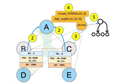
Figure 4. On-Demand SR Multicast Tree
A assigns Tree-ID 20 and invokes a Create an SR multicast tree request by sending the multicast router and tree ID information
(A, 20) towards SR-PCE.
A announces BGP AD Selective PMSI (or S-PMSI) route with PTA (A, 20). A sets the leaf-info-required to discover endpoint interest
set.
Selective PMSI - Traffic multicast by a PE on an S-PMSI is received by some PEs in the MVPN. S-PMSIs are generated by Selective P-tunnels.
E has a receiver behind it, and announces a BGP-AD leaf route towards A. A discovers service endpoint E for the on-demand
tree.
A invokes an Add SR multicast leaf router request (for E) to SR-PCE.
SR-PCE computes and generates the multicast tree information for all the routers that are part of the tree.
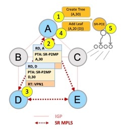
Figure 5. Optimal Multicast Tree
A decides to optimize a flow and assigns Tree-ID 30 and invokes a Create an SR multicast tree request by sending the multicast
router and tree ID information (A, 30) towards SR-PCE.
A announces BGP AD I-PMSI route with PTA (A,30). A sets the leaf-info-required to discover endpoint interest set.
D has a receiver behind it, and announces a BGP-AD leaf route towards A. A discovers service endpoint D for optimized flow.
A invokes an Add SR multicast leaf router request (for D) to SR-PCE.
SR-PCE computes and generates the multicast tree information for all the routers that are part of the tree.
Configurations
Head End Router Configuration (Router A) - The following configuration is specific to the head end router.
Configure TE Constraints and Optimization Parameters
An affinity bit-map is created so that it can be applied to a link or interface.
Router(config-sr-te)# affinity-map name 10 bit-position 24
Router(config-sr-te)# commit
An affinity (or relationship) is created between the SR policy path and the link color so that SR-TE computes a path that
includes or excludes links, as specified. The head-end router automatically follows the actions defined in the ODN template
(for color 10) upon the arrival of VPN routes with a BGP color extended community that matches color 10.
Router(config)# segment-routing traffic-engineering
Router(config-sr-te)# on-demand color 10 dynamic
Router(config-sr-te-color-dyn)# affinity include-all name red
Router(config-sr-te-color-dyn)# affinity include-any name blue
Router(config-sr-te-color-dyn)# affinity exclude-any name green
Router(config-sr-te-color-dyn)# metric type te
Router(config-sr-te-color-dyn)# commit
The SR policy configuration on the head-end router A will be sent to the SR-PCE server, after a connection is established
between A and SR-PCE.
Multicast Router Configuration
Configure PCEP Client on Multicast Routers
Associate each multicast router as a client of the SR-PCE server. The pce address ipv4 command specifies the SR-PCE server’s IP address.
Alternatively, you can configure FRR for each individual tree using the following configuration. The lfa keyword under a specific multicast policy (tree1 in this example) enables LFA FRR function for the specified SR multicast P2MP tree.
For dynamic trees, L-flag in LSP Attributes PCEP object controls FRR on a tree.
You can create FRR node sets using the frr-node-set from ipv4address and frr-node-set to ipv4address commands to specify the from and to paths on a multicast router that requires FRR protection. In this configuration, the PCE server is configured to manage the
FRR function for traffic from 192.168.0.3 sent towards 192.168.0.4 and 192.168.0.5.
Router(config)# pce
Router(config-pce)# address ipv4 192.168.0.5
Router(config-pce)# segment-routing traffic-eng
Router(config-pce-sr-te)# p2mp
Router(config-pce-sr-te-p2mp)# frr-node-set from ipv4 192.168.0.3
Router(config-pce-sr-te-p2mp)# frr-node-set to ipv4 192.168.0.4
Router(config-pce-sr-te-p2mp)# frr-node-set to ipv4 192.168.0.5
Router(config-pce-sr-te-p2mp)# commit
Disable ECMP load splitting
To disable ECMP load splitting of different trees on the SR-PCE server, configure the multipath-disable command.
The following MVPN configurations are required for VPN end-points, the 3 PE routers.
Configure Default MDT SR P2MP MVPN Profile
In this configuration, an MDT profile of the type default is created, and the SR multicast policy with color 10 will be used to send IP multicast traffic, as per the constraints and
optimizations of the policy, through the multicast tree.
You can also specify the FRR LFA function with the mdt default segment-routing mpls fast-reroute lfa command.
In this configuration, an MDT profile of the type partitioned is created, and the SR multicast policy with color 10 will be used to send IP multicast traffic, as per the constraints and
optimizations of the policy, through the multicast tree.
You can also specify the FRR LFA function with the mdt partitioned segment-routing mpls fast-reroute lfa command.
The following Data MVPN configuration is required at the Ingress PE (router A) where the multicast flows need to be steered
onto the data MDT for SR multicast traffic flow.
Note - Data MDT can be configured for Default and Partitioned profiles.
Configure Data MDT for SR P2MP MVPN
In this configuration, an MDT profile of the type data is created, and the SR multicast policy with color 10 will be used to send IP multicast traffic, as per the constraints and
optimizations of the policy, through the multicast tree.
You can enable the FRR LFA function with the mdt data segment-routing mpls fast-reroute lfa command. This enables LFA FRR for SR multicast trees created for all data MDT profiles.
As an alternative to the color keyword, you can specify a route policy in the route-policy command, and define the route policy separately (as mentioned in the next configuration).
The threshold command specifies the threshold above which a multicast flow is switched onto the data MDT. The immediate-switch keyword enables an immediate switch of a multicast flow to the data MDT, without waiting for threshold limit to be crossed.
The customer-route-acl keyword specifies an ACL to enable specific multicast flows to be put on to the data MDT.
color and fast-reroute lfa keywords are mutually exclusive with the route-policy configuration. The objective is to apply constraints (through color) or FRR (through LFA protection) to either all data MDTs, or apply them selectively per data MDT, using the set on-demand-color and set fast-reroute lfa options in the route policy (configured in the mdt data configuration).
Router(config)# multicast-routing vrf cust1
Router(config-mcast-cust1)# address-family ipv4
Router(config-mcast-cust1-ipv4)# mdt data segment-routing mpls 2 color 10
Router(config-mcast-cust1-ipv4)# commit
Route Policy Example
The route policy designates multicast flow-to-SR multicast policy mapping, with different colors.
With this configuration, IP multicast flows for the 232.0.0.1 multicast group are steered into the SR multicast policy created
with the on-demand color 10, while flows for 232.0.0.2 are steered into the policy created with color 20.
The data MDT SR multicast tree created for the 232.0.0.2 multicast group is enabled with FRR LFA protection.
Route policies can also be used to match other parameters, such as source address.
Router(config)# route-policy TSID-DATA
Router(config-rpl)# if destination in (232.0.0.1) then
Router(config-rpl-if)# set on-demand-color 10
Router(config-rpl-if)# pass
Router(config-rpl-if)# elseif destination in (232.0.0.2) then
Router(config-rpl-elseif)# set on-demand-color 20
Router(config-rpl-elseif)# set fast-reroute lfa
Router(config-rpl-elseif)# pass
Router(config-rpl-elseif)# endif
Router(config-rpl)# end-policy
Router(config)# commit
Configure MVPN BGP Auto-Discovery for SR P2MP
The following configuration is required on all PE routers, and is mandatory for default MDT, partitioned MDT, and data MDT.
Configure the BGP Auto-Discovery function for transporting IP multicast traffic.
View MVPN Context Information - You can view MVPN VRF context information with these commands.
View Default MDT Configuration
This command displays SR multicast tree information, including the MDT details (of default type, etc), and customer VRF information (route target, route distinguisher, etc).
This command displays SR multicast tree information, including the MDT details (of partitioned type, etc), and customer VRF information (route target, route distinguisher, etc).
This command displays SR multicast tree information on the PE router that receives the multicast traffic on the SP network.
The information includes PE router details, MDT details, Tree-SID details, and the specified customer VRF information.
Router# show mvpn vrf vpn1 pe

MVPN Provider Edge Router information

VRF : vpn1

PE Address : 192.168.0.3 (0x9570240)
  RD: 0:0:0 (null), RIB_HLI 0, RPF-ID 13, Remote RPF-ID 0, State: 0, S-PMSI: 2
  PPMP_LABEL: 0, MS_PMSI_HLI: 0x00000, Bidir_PMSI_HLI: 0x00000, MLDP-added: [RD 0, ID 0, Bidir ID 0, Remote Bidir ID 0], Counts(SHR/SRC/DM/DEF-MD): 0, 0, 0, 0, Bidir: GRE RP Count 0, MPLS RP Count 0RSVP-TE added: [Leg 0, Ctrl Leg 0, Part tail 0 Def Tail 0, IR added: [Def Leg 0, Ctrl Leg 0, Part Leg 0, Part tail 0, Part IR Tail Label 0
  Tree-SID Added: [Def/Part Leaf 1, Def Egress 0, Part Egress 0, Ctrl Leaf 0]
  bgp_i_pmsi: 1,0/0 , bgp_ms_pmsi/Leaf-ad: 1/1, bgp_bidir_pmsi: 0, remote_bgp_bidir_pmsi: 0, PMSIs: I 0x9570378, 0x0, MS 0x94e29d0, Bidir Local: 0x0, Remote: 0x0, BSR/Leaf-ad 0x0/0, Autorp-disc/Leaf-ad 0x0/0, Autorp-ann/Leaf-ad 0x0/0
 IIDs: I/6: 0x1/0x0, B/R: 0x0/0x0, MS: 0x1, B/A/A: 0x0/0x0/0x0

  Bidir RPF-ID: 14, Remote Bidir RPF-ID: 0
  I-PMSI:   Unknown/None (0x9570378)
  I-PMSI rem:  (0x0)
  MS-PMSI:   Tree-SID [524290, 192.168.0.3] (0x94e29d0)
  Bidir-PMSI:  (0x0)
  Remote Bidir-PMSI:  (0x0)
  BSR-PMSI:  (0x0)
  A-Disc-PMSI:  (0x0)
  A-Ann-PMSI:  (0x0)
  RIB Dependency List: 0x0
  Bidir RIB Dependency List: 0x0
    Sources: 0, RPs: 0, Bidir RPs: 0
View Partitioned MDT Egress PE Configuration
This command displays SR multicast tree information on the MVPN egress PE router that sends multicast traffic from the SP
network towards multicast receivers in the destination sites. The information includes PE router, Tree-SID, MDT, and the specified
customer VRF details.
Router# show mvpn vrf vpn1 pe

MVPN Provider Edge Router information

PE Address : 192.168.0.4 (0x9fa38f8)
  RD: 1:10 (valid), RIB_HLI 0, RPF-ID 15, Remote RPF-ID 0, State: 1, S-PMSI: 2
  PPMP_LABEL: 0, MS_PMSI_HLI: 0x00000, Bidir_PMSI_HLI: 0x00000, MLDP-added: [RD 0, ID 0, Bidir ID 0, Remote Bidir ID 0], Counts(SHR/SRC/DM/DEF-MD): 1, 1, 0, 0, Bidir: GRE RP Count 0, MPLS RP Count 0RSVP-TE added: [Leg 0, Ctrl Leg 0, Part tail 0 Def Tail 0, IR added: [Def Leg 0, Ctrl Leg 0, Part Leg 0, Part tail 0, Part IR Tail Label 0
  Tree-SID Added: [Def/Part Leaf 0, Def Egress 0, Part Egress 1, Ctrl Leaf 0]
  bgp_i_pmsi: 1,0/0 , bgp_ms_pmsi/Leaf-ad: 1/0, bgp_bidir_pmsi: 0, remote_bgp_bidir_pmsi: 0, PMSIs: I 0x9f77388, 0x0, MS 0x9fa2f98, Bidir Local: 0x0, Remote: 0x0, BSR/Leaf-ad 0x0/0, Autorp-disc/Leaf-ad 0x0/0, Autorp-ann/Leaf-ad 0x0/0
 IIDs: I/6: 0x1/0x0, B/R: 0x0/0x0, MS: 0x1, B/A/A: 0x0/0x0/0x0

  Bidir RPF-ID: 16, Remote Bidir RPF-ID: 0
  I-PMSI:   Unknown/None (0x9f77388)
  I-PMSI rem:  (0x0)
  MS-PMSI:   Tree-SID [524292, 192.168.0.4] (0x9fa2f98)
  Bidir-PMSI:  (0x0)
  Remote Bidir-PMSI:  (0x0)
  BSR-PMSI:  (0x0)
  A-Disc-PMSI:  (0x0)
  A-Ann-PMSI:  (0x0)
  RIB Dependency List: 0x9f81370
  Bidir RIB Dependency List: 0x0
    Sources: 1, RPs: 1, Bidir RPs: 0
View Data MDT Information
The commands in this section displays SR multicast tree information for data MDTs. The information includes cache, router-local, and remote MDT information.
View Data MDT Cache Information
Router# show pim vrf vpn1 mdt cache
Core Source      Cust (Source, Group)                Core Data        Expires
192.168.0.3      (26.3.233.1, 232.0.0.1)             [tree-id 524292]  never

192.168.0.4      (27.3.233.6, 232.0.0.1)             [tree-id 524290]  never

   Leaf AD:  192.168.0.3
View Local MDTs Information
Router# show pim vrf vpn1 mdt sr-p2mp local

Tree                           MDT             Cache DIP Local VRF Routes  On-demand
Identifier                     Source          Count     Entry Using Cache Color
[tree-id 524290 (0x80002)]     192.168.0.4     1     N   Y     1           10
   Tree-SID Leaf:  192.168.0.3
View Remote MDTs Information
Router # show pim vrf vpn1 mdt sr-p2mp remote

Tree                           MDT             Cache DIP Local VRF Routes  On-demand
Identifier                     Source          Count     Entry Using Cache Color
[tree-id 524290 (0x80002)]     192.168.0.4     1     N   N     1           0
View MRIB MPLS Forwarding Information
This command displays labels used for transporting IP multicast traffic, on a specified router.
Router# show mrib mpls forwarding

LSP information (XTC) :
  LSM-ID: 0x00000, Role: Head, Head LSM-ID: 0x80002
    Incoming Label       : (18000)
    Transported Protocol : <unknown>
    Explicit Null        : None
    IP lookup            : disabled

    Outsegment Info #1 [H/Push, Recursive]:
      OutLabel: 18000, NH: 192.168.0.3, Sel IF: GigabitEthernet0/2/0/0

LSP information (XTC) :
  LSM-ID: 0x00000, Role: Tail, Peek
  RPF-ID: 0x00011, Assoc-TIDs: 0xe0000011/0x0, MDT: TRmdtvpn1
    Incoming Label       : 18001
    Transported Protocol : <unknown>
    Explicit Null        : None
    IP lookup            : enabled

    Outsegment Info #1 [T/Pop]:
      No info.
SR-PCE Show Commands
View Tree Information On PCE Server
This command displays SR multicast tree information on the SR-PCE server.
For dynamic SR multicast trees created for MVPN, the show command has filters to view root multicast router and Tree-ID information. When the root router is specified, all multicast
trees from that root are displayed. When root and Tree-ID are specified, only the specified tree information is displayed.
The following output shows that LFA FRR is enabled on the hop from rtrR to rtrM. Unlike typical multicast replication where
the address displayed is the remote address on the link to a downstream router, the IP address 192.168.0.3 (displayed with
an exclamation mark) is the router-ID of the downstream router rtrM. The output also displays the LFA FRR state for the multicast
tree.
For SR multicast policies originated locally on the router (root router of a dynamic MVPN multicast policy) additional policy
information is displayed. The information includes color, end points, and whether LFA FRR is requested by the local application.
When the SR-PCE server enables LFA FRR on a specific hop, the outgoing information shows the address of the next router with
an exclamation mark and None is displayed for the outgoing interface.
For dynamic SR multicast trees created for MVPN, the show command has filters for displaying root multicast router and Tree-ID information. When the root router is specified, all
multicast trees for that root are displayed. When root and Tree-ID are specified, only the specified tree information is displayed.
This feature allows Dynamic Tree Segment Identifier (Tree-SID) deployment where IPv6 Multicast payload is used for optimally
transporting IP VPN multicast traffic over the provider network, using SR-PCE as a controller. This implementation supports
IPv6 only for the Dynamic Tree-SID. Currently, the Static Tree-SID supports IPV4 payloads only, not the IPv6 payloads.
Overview of Multicast VPN: Tree-SID Multicast VPN
Typically, a customer’s IP VPN is spread across VPN sites. IP VPN customer traffic is sent from one site to another over a
VPN Service Provider (SP) network.
When IP Multicast traffic within a (BGP/MPLS) IP VPN is transported over a provider network (say, from VPN1-Site-A to VPN1-Site-B, as shown in the image), the provider network requires protocols and procedures to optimally transport multicast traffic
from a multicast sender in Site-A to multicast receivers in Site-B.
This use case explains how to enable SR multicast for a provider network, and efficiently transport IP VPN multicast traffic
(sent from VPN1-Site-A and) received at PE router A, through to PE routers D and E, toward receivers in sites VPN1-Site-B and VPN1-Site-C.
Figure 6. IP VPN Multicast Traffic Flow Over A Provider Network
To enable the Multicast VPN: Tree-SID multicast VPN feature, the following protocols and software applications are used:
OSPF/IS-IS - The underlay network is created with OSPF/IS-IS routing protocol, and reachability is established across the network. See
Configure Segment Routing for IS-IS Protocol or Configure Segment Routing for OSPF Protocol chapter for details, within this Guide.
BGP Multicast VPN (multicast VPN) – The PE routers (A, D, and E) are IP VPN endpoints for IP Multicast traffic arriving at the provider network (at PE router
A) and exiting the provider network (at PE routers D and E). So, BGP multicast VPN is enabled on the PE routers. NSO is used
to configure BGP multicast VPN on the PE routers. See, Configure Segment Routing for BGP chapter for details, within this guide
BGP Auto-Discovery (AD) - To enable distributed VPN endpoint discovery and C-multicast flow mapping and signaling, BGP AD function is configured on
the PE routers. A BGP Auto-Discovery route contains multicast router (loopback IP address) and tree identity (segment ID)
information. It carries the information in the Provider Multicast Service Interface (PMSI) Tunnel Attribute (PTA). See, Configure Segment Routing for BGP chapter for details, within this guide
C-multicast states are signaled using BGP. See, Configure Segment Routing for BGP chapter for details, within this guide
SR - To transport IP Multicast traffic between the VPN endpoints (PE routers A, D, and E), Provider (or P-) tunnels are used.
In a P-tunnel, the PE devices are the tunnel endpoints. P-tunnels can be generated using different technologies (RSVP-TE,
point-to-multipoint LSPs, PIM trees, mLDP point-to-multipoint LSPs, and mLDP MP2MP LSPs). In this use case, Segment Routing
(SR) is used for its benefits that were noted earlier.
With SR and SR-PCE, a Tree-SID point-to-multipoint (P2MP) segment is used to create P-Tunnels for multicast VPN. You can specify
SR policy optimization objectives (such as metrics) and constraints (such as affinity) in an SR policy and send it to the SR-PCE controller, so that it can dynamically create SR multicast trees for traffic flow.
SR-PCE - This is a controller which, based on the provided SR policy information, computes optimal paths for a multicast tree, and
deploys the tree forwarding state on the multicast routers. When a topology change occurs, SR-PCE automatically computes a
new, optimal multicast tree, and deploys the new tree forwarding state on the multicast routers.
Tree-SID multicast VPN
The topology remains the same, with PE routers A, D, and E acting as VPN endpoints for carrying IP VPN multicast traffic.
For SR, A is designated as the SR headend router, and D and E are designated as the SR endpoints.
For multicast traffic, A is the root of the SR multicast tree, and D and E are leaf routers of the tree. B and C are the other
multicast routers. The objective is to send the IP Multicast traffic arriving at A to D and E, as needed.
Figure 7. Multicast Tree
A discovers leaf routers’ information through BGP multicast VPN.
Path Computation Element Protocol (PCEP) is used for the SR multicast policy communication between A and the SR-PCE server,
and communication between PE routers and the SR-PCE server.
When the headend router SR policy is created on A, and PCEP configurations are enabled on the SR-PCE server and all multicast
routers, SR-PCE receives the SR policy and leaf router identity information from A.
Based on the policy information it receives, including traffic engineering objectives and constraints, SR-PCE builds multicast
distribution trees in the underlay for efficient VPN traffic delivery.
SR-PCE assigns an SID for the SR multicast tree policy, and deploys the multicast tree forwarding state on the multicast routers.
When IP Multicast traffic is sent from VPN1-SiteA to PE router A, it steers it into the SR policy, and sends it toward D and
E, which forward it to multicast traffic receivers in the sites VPN1-SiteB and VPN1-SiteC.
When a leaf or multicast router is added or removed, PE router A updates the SR multicast policy and sends it to SR-PCE. SR-PCE
computes new multicast routes, and deploys the multicast tree forwarding state information on the multicast routers.
SR Multicast Tree Types
This is an overview of the types of SR multicast trees that you can configure, depending on your requirement. You can create
the following tree types for IP VPN multicast flow in the provider network:
Full Mesh Multicast Tree
Figure 8. Full Mesh Multicast Tree
A assigns Tree-ID 10 and invokes a Create an SR multicast tree request by sending the multicast router and tree ID information
(A, 10) toward SR-PCE.
A announces BGP AD Inclusive PMSI (I-PMSI) route with the PTA (A, 10). Inclusive PMSI - Traffic that is multicast by a PE
router on an I-PMSI is received by all other PEs in the multicast VPN. I-PMSIs are generated by Inclusive P-tunnels.
A discovers VPN endpoints D and E from their BGP AD Type I-PMSI route messages.
A invokes an Add SR multicast leaf router request (for D and E) to SR-PCE.
SR-PCE computes and generates the multicast tree forwarding state information on all the routers that are part of the tree.
On-Demand SR Multicast Tree
Figure 9. On-Demand SR Multicast Tree
A assigns Tree-ID 20 and invokes a Create an SR multicast tree request by sending the multicast router and tree ID information
(A, 20) toward SR-PCE.
A announces BGP AD Selective PMSI (or S-PMSI) route with PTA (A, 20). A sets the leaf-info-required to discover endpoint interest
set.
Selective PMSI - Traffic multicast by a PE on an S-PMSI is received by some PEs in the multicast VPN. S-PMSIs are generated by Selective
P-tunnels.
E has a receiver behind it, and announces a BGP-AD leaf route toward A. A discovers service endpoint E for the on-demand tree.
A invokes an Add SR multicast leaf router request (for E) to SR-PCE.
SR-PCE computes and generates the multicast tree information for all the routers that are part of the tree.
Optimal Multicast Tree
Figure 10. Optimal Multicast Tree
A decides to optimize a flow and assigns Tree-ID 30 and invokes a Create an SR multicast tree request by sending the multicast
router and tree ID information (A, 30) toward SR-PCE.
A announces BGP AD I-PMSI route with PTA (A, 30). A sets the leaf-info-required to discover endpoint interest set.
D has a receiver behind it, and announces a BGP-AD leaf route toward A. A discovers service endpoint D for optimized flow.
A invokes an Add SR multicast leaf router request (for D) to SR-PCE.
SR-PCE computes and generates the multicast tree information for all the routers that are part of the tree.
Multicast: Cisco Nonstop Forwarding for Tree-SID
Table 3. Feature History Table
Feature Name
Release Information
Feature Description
Multicast: Cisco Nonstop Forwarding for Tree-SID
Release 7.10.1
Starting from this release, Multicast Nonstop Forwarding supports Tree-SID (Tree Segment Identifier). This ensures that traffic
forwarding continues without interruptions whenever the active RSP fails over to the standby RSP.
This feature prevents hardware or software failures on the control plane from disrupting the forwarding of existing packet
flows through the router for Tree-SID. Thus, ensuring improved network availability, network stability, preventing routing
flaps, and no loss of user sessions while the routing protocol information is being restored.
This section captures only the Cisco Nonstop Forwarding feature in relation with Tree-SID. For more information on the Cisco
Nonstop Forwarding feature, see Multicast Nonstop Forwarding.
Multicast now supports hitless Route Processor Fail Over (RPFO). During RPFO, the software deletes IP routes from the Static
Tree-SID profile in the headend router. The Dynamic Tree-SID does not have this issue, because in this case, the BGP advertises
the states that supports Nonstop Routing (NSR). To overcome this problem for static Tree-SID, there are checkpoints to check
the feature in Protocol Independent Multicast (PIM). On switchover, the checkpoint reads to check if the feature is there
or not and push Protocol Independent Multicast (PIM) to Cisco Nonstop Forwarding state.
Verification Steps
The show mrib nsf private command is enhanced to display the XTC info as well.
Router#show mrib nsf private
Mon Jul 31 13:27:05.056 UTC
IP MRIB Non-Stop Forwarding Status:
Multicast routing state: Normal
   NSF Lifetime:       00:03:00
   Respawn Count: 6
   Last NSF On triggered: Tue Jul 25 13:20:49 2023, 6d00h
   Last NSF Off triggered: Tue Jul 25 13:22:49 2023, 6d00h
   Last NSF ICD Notification sent: Tue Jul 25 13:22:49 2023, 6d00h
   Last Remote NSF On triggered: Tue Jul 25 13:10:18 2023, 6d00h
   Last Remote NSF Off triggered: Tue Jul 25 13:10:27 2023, 6d00h
   Last Label TE NSF On triggered: Tue Jul 25 13:10:18 2023, 6d00h
   Last Label TE NSF Off triggered: Tue Jul 25 13:10:27 2023, 6d00h
   Last Label mLDP NSF On triggered: Tue Jul 25 13:10:18 2023, 6d00h
   Last Label mLDP NSF Off triggered: Tue Jul 25 13:10:27 2023, 6d00h
   Last Label PIM NSF On triggered: Tue Jul 25 13:20:49 2023, 6d00h
   Last Label PIM NSF Off triggered: Tue Jul 25 13:22:49 2023, 6d00h
   Last Label PIM6 NSF On triggered: Tue Jul 25 13:31:22 2023, 5d23h
   Last Label PIM6 NSF Off triggered: Tue Jul 25 13:33:22 2023, 5d23h
   Last Label XTC NSF On triggered: Tue Jul 25 13:41:51 2023, 5d23h
   Last Label XTC NSF Off triggered: Tue Jul 25 13:41:52 2023, 5d23h

IP NSF :- Active: N, Assume N
MRIB connect timer: Inactive
NSF statistics:
   Enabled Cnt - 4, Disabled Cnt - 4
   Last Enabled: 6d00h, Last Disabled: 6d00h
Multicast COFO routing state: Normal
Current LMRIB clients: LDP RSVP_TE PIM PIM6 XTC
LMRIB NSF clients: LDP RSVP_TE PIM PIM6 XTC
Converged LMRIB clients: LDP RSVP_TE PIM PIM6 XTC


 Feedback