Segment Routing Configuration Guide for Cisco 8000 Series Routers, IOS XR Release 24.1.x, 24.2.x, 24.3.x
Bias-Free Language
The documentation set for this product strives to use bias-free language. For the purposes of this documentation set, bias-free is defined as language that does not imply discrimination based on age, disability, gender, racial identity, ethnic identity, sexual orientation, socioeconomic status, and intersectionality. Exceptions may be present in the documentation due to language that is hardcoded in the user interfaces of the product software, language used based on RFP documentation, or language that is used by a referenced third-party product. Learn more about how Cisco is using Inclusive Language.
Configure Segment Routing over IPv6 (SRv6) with Micro-SIDs
Table 1. Feature History Table
Feature Name
Release
Description
SRv6 with Micro-Segment (uSID)
Release 7.5.2
This release introduces support for Segment Routing over IPv6 data plane using Micro SIDs (uSIDs).
This feature allows the source router to encode multiple SRv6 uSID instructions within a single 128-bit SID address. Such
functionality allows for efficient and compact SRv6 SID representation with a low MTU overhead
Segment Routing for IPv6 (SRv6) is the implementation of Segment Routing over the IPv6 dataplane.
In a Segment Routing over IPv6 (SRv6) network, an IPv6 address serves as the segment identifier (SID). The source router can
encode multiple SRv6 uSID instructions within a single 128-bit SID address. Such a SID address is called a uSID Carrier.
SRv6 uSIDs provides low MTU overhead; for example, 6 uSIDs per uSID carrier results in 18 source-routing waypoints in only
40 bytes of overhead (in SRH).
Segment Routing over IPv6 Overview
Segment Routing (SR) can be applied on both MPLS and IPv6 data planes. Segment Routing over IPv6 (SRv6) extends Segment Routing
support with IPv6 data plane.
In an SR-MPLS enabled network, an MPLS label represents an instruction. The source nodes programs the path to a destination
in the packet header as a stack of labels.
SRv6 introduces the Network Programming framework that enables a network operator or an application to specify a packet processing
program by encoding a sequence of instructions in the IPv6 packet header. Each instruction is implemented on one or several
nodes in the network and identified by an SRv6 Segment Identifier (SID) in the packet. The SRv6 Network Programming framework
is defined in IETF RFC 8986 SRv6 Network Programming.
In SRv6, an IPv6 address represents an instruction. SRv6 uses a new type of IPv6 Routing Extension Header, called the Segment
Routing Header (SRH), in order to encode an ordered list of instructions. The active segment is indicated by the destination
address of the packet, and the next segment is indicated by a pointer in the SRH.
Next header—Identifies the type of header immediately following the SRH.
Hdr Ext Len (header extension length)—The length of the SRH in 8-octet units, not including the first 8 octets.
Segments left—Specifies the number of route segments remaining. That means, the number of explicitly listed intermediate nodes
still to be visited before reaching the final destination.
Last Entry—Contains the index (zero based) of the last element of the segment list.
Flags— Contains 8 bits of flags.
Tag—Tag a packet as part of a class or group of packets like packets sharing the same set of properties.
Segment list—128-bit IPv6 addresses representing the nth segment in the segment list. The segment list encoding starts from the last segment of the SR policy (path). That means
the first element of the segment list (Segment list [0]) contains the last segment of the SR policy, the second element contains
the penultimate segment of the SR policy and so on.
In SRv6, a SID represents a 128-bit value, consisting of the following three parts:
Locator: This is the first part of the SID with most significant bits and represents an address of a specific SRv6 node.
Function: This is the portion of the SID that is local to the owner node and designates a specific SRv6 function (network
instruction) that is executed locally on a particular node, specified by the locator bits.
Args: This field is optional and represents optional arguments to the function.
The locator part can be further divided into two parts:
SID Block: This field is the SRv6 network designator and is a fixed or known address space for an SRv6 domain. This is the
most significant bit (MSB) portion of a locator subnet.
Node Id: This field is the node designator in an SRv6 network and is the least significant bit (LSB) portion of a locator
subnet.
SRv6 Node Roles
Each node along the SRv6 packet path has a different functionality:
Source node—A node that can generate an IPv6 packet with an SRH (an SRv6 packet), or an ingress node that can impose an SRH
on an IPv6 packet.
Transit node—A node along the path of the SRv6 packet (IPv6 packet and SRH). The transit node does not inspect the SRH. The
destination address of the IPv6 packet does not correspond to the transit node.
Endpoint node—A node in the SRv6 domain where the SRv6 segment is terminated. The destination address of the IPv6 packet with
an SRH corresponds to the end point node. The segment endpoint node executes the function bound to the SID
SRv6 Micro-Segment (uSID)
The SRv6 micro-segment (uSID) is an extension of the SRv6 architecture. It leverages the SRv6 Network Programming architecture
to encode several SRv6 Micro-SID (uSID) instructions within a single 128-bit SID address. Such a SID address is called a uSID
Carrier.
Throughout this chapter, we will refer to SRv6 micro-segment as “uSID”.
The SRv6 uSID provides the following benefits:
Leverages the SRv6 Network Programming with no change. SRv6 uSID is a new pseudo code in the existing SRv6 network programming
framework.
Leverages the SRv6 data plane (SRH) with no change. Any SID in the destination address or SRH can be an SRv6 uSID carrier.
Leverages the SRv6 control plane with no change.
Ultra-Scale—Scalable number of globally unique nodes in the domain, for example:
16-bit uSID ID size: 65k uSIDs per domain block
32-bit uSID ID size: 4.3M uSIDs per domain block
Lowest MTU overhead
6 uSIDs per uSID carrier
For example, 18 source-routing waypoints in only 40 bytes of overhead
+ H.Encaps.Red with an SRH of 40 bytes (8 fixed + 2 * 16 bytes)
+ 6 uSIDs in DA and 12 in SRH
Hardware-friendliness:
Leverages mature hardware capabilities (inline IP Destination Address edit, IP Destination Address longest match).
Avoids any extra lookup in indexed mapping tables.
A micro-program with 6 or fewer uSIDs requires only legacy IP-in-IP encapsulation behavior.
Scalable Control Plane:
Summarization at area/domain boundary provides massive scaling advantage.
No routing extension is required, a simple prefix advertisement suffices.
Seamless Deployment:
A uSID may be used as a SID (the carrier holds a single uSID).
The inner structure of an SR Policy can stay opaque to the source. A carrier with uSIDs is just seen as a SID by the policy
headend Security.
Leverages SRv6's native SR domain security.
SRv6 Head-End Behaviors
Table 2. Feature History Table
Feature Name
Release Information
Feature Description
H.Insert.Red Headend Behavior for SRv6 on Cisco Silicon One P100-based Line Cards
Release 24.3.1
Introduced in this release on: Modular Systems (8800 [LC ASIC: P100])(select variants only*)
With H.Insert.Red head-end behavior, you can effectively steer traffic into an SR policy, allowing for fast rerouting, traffic
optimization, and simplified path management without additional encapsulation.
The H.Insert.Red head-end behavior enables the router to insert a Segment Routing Header (SRH) directly into an existing IPv6
packet.
The feature is supported only on Cisco Silicon One P100-based line cards in Cisco 8800 modular routers operating in P100
compatibility mode.
* This feature is supported on:
88-LC1-36EH
88-LC1-12TH24FH-E
88-LC1-52Y8H-EM
SR policies define the behavior of headend routers in managing and directing traffic through a network. The headend router
is responsible for initiating and enforcing these policies. SR supports these headend behaviors.
Starting from Cisco IOS XR Release 24.3.1, the H.Insert.Red headend behavior is supported only on routers with P100 based line cards. Based on the available line cards,
the default headend behavior varies. The table summarizes the default behavior.
If the router has ….
Then the default headend behavior is...
Cisco Silicon One P100-based line cards
H.Insert.Red
Cisco Silicon One Q200-based line cards
H.Encap.Red
a mix of Cisco Silicon One P100- and Q200- based line cards
H.Encap.Red
Use the hw-module profile npu-compatibility command to switch the NPU operating mode to Q200. You need to manually reload the router to activate the NPU compatibility
mode.
Comparision between H.Encaps.Red and H.Insert.Red Headend Behaviors
This table describes the difference between the H.Encaps and H.Insert.Red head-end behaviors.
Headend Behaviors
H.Encaps.Red
H.Insert.Red
Definition
The H.Encap.Red is a headend behavior that encapsulates the original packet into a new IPv6 packet with an Segment Routing Header (SRH).
The H.insert.Red is a headend behavior that inserts an SRH into the original IPv6 packet without encapsulating it into a new IPv6 packet.
Header Manipulation
A new IPv6 header with an SRH is added to the packet, encapsulating the original packet.
The SRH is inserted into the packet by modifying the existing IPv6 header.
Packet Size
The packet size increases as it includes both the SRH and an additional IPv6 header.
The packet size is smaller compared to H.encaps headend behavior. There is no extra IPv6 header and that helps maintain the
packet size.
Processing at Intermediate Nodes
Intermediate nodes process the packet by examining the outer IPv6 header's destination address and the SRH.
Intermediate nodes process the packet by examining the inserted SRH and forwarding the packet based on the active segment.
Termination Process
Ultimate Segment Pop
The termination process involves decapsulation, where the outer IPv6 header and SRH are removed to reveal the original packet.
Penultimate Segment Pop (PSP)
The termination process involves the removal of the SRH when the packet reaches the end of the SR Policy.
The following is a subset of defined SRv6 endpoint behaviors that can be associated with a SID.
End—Endpoint function. The SRv6 instantiation of a Prefix SID [RFC8402].
End.X—Endpoint with Layer-3 cross-connect. The SRv6 instantiation of an Adj SID [RFC8402].
End.DX6—Endpoint with decapsulation and IPv6 cross-connect (IPv6-L3VPN - equivalent to per-CE VPN label).
End.DX4—Endpoint with decapsulation and IPv4 cross-connect (IPv4-L3VPN - equivalent to per-CE VPN label).
End.DT6—Endpoint with decapsulation and IPv6 table lookup (IPv6-L3VPN - equivalent to per-VRF VPN label).
End.DT4—Endpoint with decapsulation and IPv4 table lookup (IPv4-L3VPN - equivalent to per-VRF VPN label).
End.DT46—Endpoint with decapsulation and specific IP table lookup (IP-L3VPN - equivalent to per-VRF VPN label).
End.DX2—Endpoint with decapsulation and L2 cross-connect (L2VPN use-case).
End.B6.Encaps—Endpoint bound to an SRv6 policy with encapsulation. SRv6 instantiation of a Binding SID.
End.B6.Encaps.RED—End.B6.Encaps with reduced SRH. SRv6 instantiation of a Binding SID.
SRv6 Endpoint Behavior Variants
Depending on how the SRH is handled, different behavior variants are defined for the End and End.X behaviors. The End and
End.X behaviors can support these variants, either individually or in combinations.
Penultimate Segment Pop (PSP) of the SRH variant—An SR Segment Endpoint Nodes receive the IPv6 packet with the Destination Address field of the IPv6 Header equal to its SID
address.
A penultimate SR Segment Endpoint Node is one that, as part of the SID processing, copies the last SID from the SRH into the
IPv6 Destination Address and decrements the Segments Left value from one to zero.
The PSP operation takes place only at a penultimate SR Segment Endpoint Node and does not happen at non-penultimate endpoint
nodes. When a SID of PSP-flavor is processed at a non-penultimate SR Segment Endpoint Node, the PSP behavior is not performed
since Segments Left would not be zero.
The SR Segment Endpoint Nodes advertise the SIDs instantiated on them via control plane protocols. A PSP-flavored SID is used
by the Source SR Node when it needs to instruct the penultimate SR Segment Endpoint Node listed in the SRH to remove the SRH
from the IPv6 header.
Ultimate Segment Pop (USP) of the SRH variant—The SRH processing of the End and End.X behaviors are modified as follows:
If Segments Left is 0, then:
Update the Next Header field in the preceding header to the Next Header value of the SRH
Decrease the IPv6 header Payload Length by 8*(Hdr Ext Len+1)
Remove the SRH from the IPv6 extension header chain
Proceed to process the next header in the packet
One of the applications of the USP flavor is when a packet with an SRH is destined to an application on hosts with smartNICs
implementing SRv6. The USP flavor is used to remove the consumed SRH from the extension header chain before sending the packet
to the host.
Ultimate Segment Decapsulation (USD) variant—The Upper-layer header processing of the End and End.X behaviors are modified as follows:
End behavior: If the Upper-layer Header type is 41 (IPv6), then:
Remove the outer IPv6 Header with all its extension headers
Submit the packet to the egress IPv6 FIB lookup and transmission to the new destination
Else, if the Upper-layer Header type is 4 (IPv4)
Remove the outer IPv6 Header with all its extension headers
Submit the packet to the egress IPv4 FIB lookup and transmission to the new destination
One of the applications of the USD flavor is the case of TI-LFA in P routers with encapsulation with H.Encaps. The USD flavor
allows the last Segment Endpoint Node in the repair path list to decapsulate the IPv6 header added at the TI-LFA Point of
Local Repair and forward the inner packet.
SRv6 uSID Terminology
The SRv6 Network Programming is extended with the following terms:
uSID—An identifier that specifies a micro-segment.
A uSID has an associated behavior that is the SRv6 function (for example, a node SID or Adjacency SID) associated with the
given ID. The node at which an uSID is instantiated is called the “Parent” node.
uSID Carrier—A 128-bit IPv6 address (carried in either in the packet destination address or in the SRH) in the following format:
uSID Block—An IPv6 prefix that defines a block of SRv6 uSIDs.
Active uSID—The first uSID that follows the uSID block.
Next uSID—The next uSID after the Active uSID.
Last uSID—The last uSID in the carrier before the End-of-Carrier uSID.
End-of-Carrier —A globally reserved uSID that marks the end of a uSID carrier. The End-of-Carrier ID is 0000. All empty uSID carrier positions must be filled with the End-of-Carrier ID; therefore, a uSID carrier can have more than
one End-of-Carrier.
The following is an example of an SRH with 3 Micro-SID carriers for a total of up to 18 micro-instructions:
The uSID carrier format specifies the type of uSID carrier supported in an SRv6 network. The format specification includes
Block size and ID size.
uSID Block
The uSID block is an IPv6 prefix that defines a block of SRv6 uSIDs. This can be an IPv6 prefix allocated to the provider
(for example, /22, /24, and so on.), or it can be any well-known IPv6 address block generally available for private use, such
as the ULA space FC/8, as defined in IETF draft RFC4193.
An SRv6 network may support more than a single uSID block.
The length of block [prefix] is defined in bits. From a hardware-friendliness perspective, it is expected to use sizes on
byte boundaries (16, 24, 32, and so on).
uSID ID
The length of uSID ID is defined in bits. From a hardware-friendliness perspective, it is expected to use sizes on byte boundaries
(8, 16, 24, 32, and so on).
The uSID carrier format is specified using the notation "Fbbuu" , where “bb” is size of block and “uu” is size of ID. For example, "F3216" is a format with a 32-bit uSID block and 16-bit uSID IDs.
SRv6 uSID Allocation Within a uSID Block
Table 3. Feature History Table
Feature Name
Release
Description
Wide LIB uSID Allocation for End.DT46 SRv6 SIDs
Release 7.5.3
This feature introduces support for Wide Local ID block (W-LIB).
W-LIB provides an extended set of IDs available for local uSID allocation that can be used when a PE with large-scale Pseudowire
termination requires more local uSIDs than provided from the LIB.
W-LIB uSID allocation is supported for End.DT46 SRv6 SIDs.
Key Concepts and Terminologies
The architecture for uSID specifies both globally scoped and locally scoped uSIDs.
Global ID block (GIB): The set of IDs available for globally scoped uSID allocation.
A globally scoped uSID is the type of uSID that provides reachability to a node. A globally scoped uSID typically identifies
a shortest path to a node in the SR domain. An IP route (for example, /48) is advertised by the parent node to each of its
globally scoped uSIDs, under the associated uSID block. The parent node executes a variant of the END behavior.
The “nodal” uSID (uN) is an example of a globally scoped behavior defined in uSID architecture.
A node can have multiple globally scoped uSIDs under the same uSID blocks (for example, one uSID per IGP flex-algorithm).
Multiple nodes may share the same globally scoped uSID (Anycast).
Local ID block (LIB): The set of IDs available for locally scoped uSID allocation.
A locally scoped uSID is associated to a local (end-point) behavior, and therefore must be preceded by a globally scoped uSID of the parent node when relying on routing to forward the packet.
A locally scoped uSID identifies a local micro-instruction on the parent node; for example, it may identify a cross-connect
to a direct neighbor over a specific interface or a VPN context. Locally scoped uSIDs are not routeable.
For example, if N1 and N2 are two different physical nodes of the uSID domain and L is a locally scoped uSID value, then N1 and N2 may bind two different behaviors to L.
Wide LIB (W-LIB): The extended set of IDs available for local uSID allocation.
The extended set of IDs is useful when a PE with large-scale Pseudowire termination requires more local uSIDs than provided
from the LIB.
Example: uSID Allocation
The request to allocate locally scoped uSIDs comes from SRv6 clients (such as IS-IS or BGP). The request can be to allocate
any available ID (dynamic allocation) or to allocate a specific ID (explicit allocation).
Consider the following example:
uSID Locator Block length: 32 bits
uSID Locator Block: FCBB:BB00::/32 (with B being a nibble value picked by operator)
uSID length (Locator Node ID / Function ID): 16 bits
uSID: FCBB:BB00:XYWZ::/48 (with XYWZ being variable nibbles)
A uSID FCBB:BB00:XYWZ::/48 is said to be allocated from its block (FCBB:BB00::/32).
A uSID is allocated from the GIB or LIB of block FCBB:BB00::/32 depending on the value of the "X" nibble:
GIB: nibble X from hex(0) to hex(D)
LIB: nibble X hex(E) or hex(F)
With this allocation scheme, the uSID Block FCBB:BB00::/32 supports up to 57343 global uSIDs (routers) with each router supporting up to 8192 local uSIDs.
For example, the following picture depicts the global uSIDs allocated for 3 nodes within the SRv6 domain.
Looking further into R1, this node also has Local uSIDs associated with uA end-point behaviors:
Function ID 0xE000 – cross-connect to L3 neighbor R2
Function ID 0xE001 – cross-connect to L3 neighbor R3
The underlay uSIDs present on R1 are:
FCBB:BB00:0001::/48
FCBB:BB00:0001:E000::/64
FCBB:BB00:0001:E001::/64
GIB and LIB – IOS-XR Implementation
In Cisco IOS XR Release 7.5.2 and earlier, the following functionality is supported:
GIB for user-assigned IDs of global segments (uNs)
LIB for dynamically assigned IDs of local segments
uA end-point behavior
Service de-multiplexing end-point behaviors (for example, End.DT, End.DX, End.DX2)
A uSID FCBB:BB00:XYWZ::/48 is said to be allocated from its block FCBB:BB00::/32.
The range of IDs supported by the Cisco IOS XR 7.5.2 and earlier implementation are as follows:
The range of IDs in the GIB is 0x000 to 0xDFFF.
The range of IDs by default in the LIB is divided as follows:
Dynamic: 0xE000 to 0xFDFF
Reserved: 0xFE00 to 0xFFFF
Figure 2. GIB/LIB
Starting with Cisco IOS XR Release 7.5.3, the following functionality is added:
Configurable explicit LIB range
Explicit LIB for user-assigned IDs of local segments
Manual uDT46 from explicit LIB
Wide LIB (W-LIB)
Configurable explicit W-LIB range
Explicit W-LIB for user-assigned IDs of local segments
Manual uDT46 from explicit W-LIB
The range of IDs supported by the IOS XR implementation are as follows:
The range of IDs in the GIB is 0x000 to 0xDFFF.
The range of IDs by default in the LIB is divided as follows:
Dynamic: 0xE000 to 0xFDFF
Explicit: 0xFE00 to 0xFEFF
Reserved: 0xFF00 to 0xFFEF and 0xFFF8 to 0xFFFF
The range of IDs by default in the W-LIB is divided as follows:
Reserved: 0xFFF0 to 0xFFF6
Explicit: 0xFFF7
Figure 3. GIB/LIB/W-LIB
SRv6 Endpoint Behaviors Associated with uSID
The SRv6 Network Programming is extended with new types of SRv6 SID endpoint behaviors:
uN—A short notation for the NEXT-CSID (Compressed SID) End behavior with a pseudocode of shift-and-lookup, and PSP/USD flavors
uA—A short notation for the NEXT-CSID End.X behavior with a pseudocode of shift-and-xconnect, and PSP/USD flavors
uDT—A short notation for the NEXT-CSID End.DT behavior with the same pseudocode as End.DT4/End.DT6/End.DT46/End.DT2U/End.DT2M
uDX—A short notation for the NEXT-CSID End.DX behavior with the same pseudocode as End.DX4/End.DX6/End.DX2
SRv6 uSID in Action - Example
This example highlights an integrated VPN and Traffic Engineering use-case leveraging SRv6 uSID.
VPNv4 site A connected to Node 1 sends packets to VPNv4 site B connected to Node 2 alongside a traffic engineered path via
Node 8 and Node 7 using a single 128-bit SRv6 SID.
Node 1 is the ingress PE; Node 2 is the egress PE.
Nodes 3, 4, 5, and 6 are classic IPv6 nodes. Traffic received on these nodes use classic IP forwarding without changing the
outer DA.
Nodes 1, 8, 7 and 2 are SRv6 capable configured with:
32-bit SRv6 block = fcbb:bb01
16-bit SRv6 ID
For example:
Node 7 uN = fcbb:bb01:0700::/48
Node 8 uN = fcbb:bb01:0800::/48
The following IGP routes are advertised:
Node 8 advertises the IGP route fcbb:bb01:0800::/48
Node 7 advertises the IGP route fcbb:bb01:0700::/48
Node 2 advertises the IGP route fcbb:bb01:0200::/48
Figure 4. Integrated VPN and Traffic Engineering SRv6 uSID Use-case
Node 1 encapsulates an IPv4 packet from VPN Site A and sends an IPv6 packet with destination address fcbb:bb01:0800:0700:0200:f001:0000:0000. This is a uSID carrier, with a list of micro-instructions (uSIDs) (0800, 0700, 0200, f001, and 0000 – indicating
the end of the instruction).
uSIDs (uNs) 0800, 0700, 0200 are used to realize the traffic engineering path to Node 2 with way points at Nodes 8 and 7.
uSID f001 is the BGP-signalled instruction (uDT4) advertized by Node 2 for the VPNv4 service
Figure 5. Node 1: End.B6.Encaps Behavior
Nodes 4 and 5 simply forward the packet along the shortest path to Node 8, providing seamless deployment through classic IPv6
nodes.
Figure 6. Node 4 and Node 5: Classic IPv6 Nodes
When Node 8 receives the packet, it performs SRv6 uN behavior (shift-and-lookup with PSP/USD). It removes its outer DA (0800)
and advances the micro program to the next micro instruction by doing the following:
Pops its own uSID (0800)
Shifts the remaining DA by 16-bits to the left
Fills the remaining bits with 0000 (End-of-Carrier)
Performs a lookup for the shortest path to the next DA (fcbb:bb01:0700::/48)
Forwards it using the new DA fcbb:bb01:0700:0200:f001:0000:0000:0000
Figure 7. Node 8: SRv6 uN Behavior (Shift and Forward)
When Node 7 receives the packet, it performs the same SRv6 uN behavior (shift-and-lookup with PSP/USD), forwarding it using
the new DA fcbb:bb01:0200:f001:0000:0000:0000:0000
Figure 8. Node 7: SRv6 uN Behavior (Shift and Forward)
Nodes 6 and 3 simply forward the packet along the shortest path to Node 2, providing seamless deployment through classic IPv6
nodes.
Figure 9. Node 6 and Node 3: Classic IPv6 Nodes
When Node 2 receives the packet, it performs an SRv6 uDT4 behavior (End.DT4—Endpoint with decapsulation and IPv4 table lookup)
to VPNv4 Site B.
Figure 10. Node 2: SRv6 uDT4 Behavior
To recap, this example showed an integrated VPN and Traffic Engineering use-case, where VPNv4 site A connected to Node 1 sent
packets to VPNv4 site B connected to Node 2 alongside a traffic engineered path via Node 8 and Node 7 using a single 128-bit
SRv6 SID:
@1: inner packet P encapsulated with outer DA fcbb:bb01:0800:0700:0200:f001:0000:0000
@4 & @5: classic IP forwarding, outer DA unchanged
@8: SRv6 uN behavior: shift and lookup, outer DA becomes fcbb:bb01:0700:0200:f001:0000:0000:0000
@7: SRv6 uN behavior: shift and lookup, outer DA becomes fcbb:bb01:0200:f001:0000:0000:0000:0000
@6 & @3: classic IP forwarding, outer DA unchanged
@2: SRv6 End.DT4: Decapsulate and IPv4 table lookup
Usage Guidelines and Limitations
General Guidelines and Limitations
Cisco IOS XR supports uSIDs with 32-bit uSID block and 16-bit uSID IDs (3216).
A single UCF format must be used for uSID locators in a SRv6 uSID domain.
Cisco IOS XR supports up to 16 uSID locator prefixes.
Multiple locator prefixes are used when configuring Anycast locators or SRv6 Flexible Algorithm instances, for example.
Cisco IOS XR supports uSID locator prefixes from different uSID blocks.
Up to 256 uSID blocks can be used across all uSID locators in the network.
SRv6 Underlay support includes:
IGP redistribution/leaking between levels
Prefix Summarization on ABR routers
IS-IS TI-LFA
Microloop Avoidance
Flex-algo
SRv6 over GRE interface is not supported
SRv6 over BVI interface is not supported
uSID Allocation Recommendation
We recommend allocating uSIDs from the private IPv6 space (IPv6 Unique Local Address [ULA] range). These addresses are not
routable outside the domain and are therefore secure.
Allocation from the public IPv6 space (Global Unicast Addresses [GUA] range) is also possible but not recommended.
For example:
Using /24 from FC::/8 ULA
SRv6 Base Block = FCBB:BB::/24, with B indicating a nibble value picked by operator.
SRv6 uSID Block = FCBB:BBVV/32, with VV indicating a nibble value picked by the operator.
256 /32 uSID blocks possible from this allocation, from block 0 (FCBB:BB00/32) to block 255(FCBB:BBFF/32)
A network slice is assigned a /32 uSID block:
FCBB:BB00/32 for min-cost slice (shortest path based on minimum IS-IS cost)
FCBB:BB08/32 for min-delay slice (shortest path based on minimum latency using Flex Algo instance 128)
Platform-Specific Guidelines and Limitations
SRv6 is supported on the following Cisco 8000 series Q200-based line cards and fixed-port routers:
Cisco 8800 with 88-LC0-36FH-M, 88-LC0-36FH, 88-LC0-34H14FH line cards
Cisco 8201-32FH
Cisco 8102-64H, 8101-32-FH
SRv6 is not supported on Q100-based line cards and fixed-port routers.
Egress marking on the outer header during SRv6 encapsulation operations (TI-LFA) is not supported.
OAM: Ping and traceroute are supported.
Cisco 8000 series routers support the following SRv6 uSID behaviors and variants:
Endpoint behaviors:
uN with PSP/USD
uA with PSP/USD
uDT4
uDT6
uDT46
Head-end behaviors:
H.Encap.Red (1 uSID carrier with up to 6 uSIDs)
H.Insert.Red is supported only on Cisco Silicon One P100-based routers.
Encapsulation Capabilities and Parameters
The following describes the Cisco 8000 series router capabilities for setting or propagating certain fields in the outer IPv6
header for SRv6 encapsulated packets:
Source address: Cisco 8000 series routers support a single source address (SA) for SRv6 encapsulated packets. The SA is derived from the
SRv6 global configuration; if not configured, it is derived from the IPv6 Loopback address.
Hop limit:
Overlay encapsulation
Default: propagate=No
The hop-limit propagate command enables propagation from inner header to outer header.
Underlay encapsulation (TI-LFA) behavior is always in propagate mode, regardless of the CLI.
Cisco 8000 series routers use the flow-label from the incoming IPv6 header. In case of USD operations, flow-label is used
from the inner IPv6 header.
During H.Encap.Red operations, if the inner packet has a flow label (non-zero value), the Cisco 8000 series routers propagate
it to the outer IPv6 header. If the flow label is not present (zero), it is computed.
P role:
Underlay H-Encap: 6 sids (1 carrier with 6 sids per carrier)
PE role:
Underlay H-Insert: 3 sids (1 carrier with 3 sids per carrier)
Overlay H-Encaps: 3 sids (1 carrier with 3 sids per carrier)
Configuring SRv6
Enabling SRv6 involves the following high-level configuration steps:
Configure SRv6 locator(s)
Enable SRv6 under IS-IS
Enable SRv6 Services under BGP
Configure SRv6 Locator Name, Prefix, and uSID-Related Parameters
This section shows how to globally enable SRv6 and configure locator.
segment-routing srv6 locators locatorlocator—Globally enable SRv6 and configure the locator.
segment-routing srv6 locators locatorlocatorprefixipv6_prefix/length—Configure the locator prefix value.
segment-routing srv6 locators locatorlocatormicro-segment behavior unode psp-usd—Specifies the locator as a micro-segment (uSID) locator as well as specifies that IGP underlay uSID (uN/uA) variant is PSP-USD
for this locator.
(Optional) Configure Algorithm Associated with Locator
segment-routing srv6 locators locator locatoralgorithmalgo—(Optional) Configure Algorithm associated with the locator. Valid values for algo are from 128 to 255.
An SRv6 Anycast locator is a type of locator that identifies a set of nodes (uN SIDs). SRv6 Anycast Locators and their associated
uN SIDs may be provisioned at multiple places in a topology.
The set of nodes (Anycast group) is configured to advertise a shared Anycast locator and uN SID. Anycast routing enables the
steering of traffic toward multiple advertising nodes. Packets addressed to an Anycast address are forwarded to the topologically
nearest nodes.
One use case is to advertise Anycast uN SIDs at exit points from an SRv6 network. Any of the nodes that advertise the common
uN SID could be used to forward traffic out of the SRv6 portion of the network to the topologically nearest node.
The following behaviors apply to Anycast Locator:
Unlike a normal locator, IS-IS does not program or advertise uA SIDs associated with an Anycast locator.
uN SIDs allocated from Anycast locators will not be used in constructing TI-LFA backup paths or Microloop Avoidance primary
paths. TI-LFA backup and Microloop Avoidance paths for an Anycast locator prefix may terminate on any node advertising that
locator, which may be different from the node terminating the original primary path.
SRv6 anycast locators may have non-zero algorithm (Flexible Algorithm) values.
Use the following commands to configure the Anycast locator and advertise Anycast prefixes associated with an interface.
segment-routing srv6 locators locatorlocatoranycast—Configure the Anycast locator
router isisinstance-idinterface Loopbackinstanceprefix-attributes anycast levellevel—Advertise the Anycast prefixes associated with an interface.
Example 1:
The following example shows how to globally enable SRv6 and configure a locator.
This example shows how to verify the overall SRv6 state from SRv6 Manager point of view. The output displays parameters in
use, summary information, and platform specific capabilities.
This example shows how to verify the locator configuration and its operational status.
Router# show segment-routing srv6 locator myLoc1 detail

Name                  ID       Algo  Prefix                    Status   Flags
--------------------  -------  ----  ------------------------  -------  --------
myLoc1                3        0     2001:0:8::/48             Up       U
  (U): Micro-segment (behavior: uN (PSP/USD))
  Interface:
    Name: srv6-myLoc1
    IFH : 0x02000120
    IPv6 address: 2001:0:8::/48
  Number of SIDs: 1
  Created: Dec 10 21:26:54.407 (02:52:26 ago)
Verifying SRv6 SIDs
This example shows how to verify the allocation of SRv6 local SIDs off locator(s).
Router# show segment-routing srv6 locator myLoc1 sid
SID                         Behavior          Context                           Owner               State  RW
--------------------------  ----------------  ------------------------------    ------------------  -----  --
2001:0:8::                  uN (PSP/USD)      'default':1                       sidmgr              InUse  Y
The following example shows how to display detail information regarding an allocated SRv6 local SID.
Router# show segment-routing srv6 locator myLoc1 sid 2001:0:8:: detail
SID                         Behavior          Context                           Owner               State  RW
--------------------------  ----------------  ------------------------------    ------------------  -----  --
2001:0:8::                  uN (PSP/USD)      'default':8                       sidmgr              InUse  Y
  SID Function: 0x8
  SID context: { table-id=0xe0800000 ('default':IPv6/Unicast), opaque-id=8 }
  Locator: 'myLoc1'
  Allocation type: Dynamic
  Created: Dec 10 22:10:51.596 (02:10:05 ago)
Similarly, you can display SID information across locators by using the show segment-routing srv6 sid command.
Configuring SRv6 under IS-IS
Intermediate System-to-Intermediate System (IS-IS) protocol already supports segment routing with MPLS dataplane (SR-MPLS).
This feature enables extensions in IS-IS to support Segment Routing with IPv6 data plane (SRv6). The extensions include advertising
the SRv6 capabilities of nodes and node and adjacency segments as SRv6 SIDs.
SRv6 IS-IS performs the following functionalities:
Interacts with SID Manager to learn local locator prefixes and announces the locator prefixes in the IGP domain.
Learns remote locator prefixes from other ISIS neighbor routers and installs the learned remote locator IPv6 prefix in RIB
or FIB.
Allocate or learn prefix SID and adjacency SIDs, create local SID entries, and advertise them in the IGP domain.
Usage Guidelines and Restrictions
The following usage guidelines and restrictions apply for SRv6 IS-IS:
An IS-IS address-family can support either SR-MPLS or SRv6, but both at the same time is not supported.
Configuring SRv6 IS-IS
To configure SRv6 IS-IS, you should enable SRv6 under the IS-IS IPv6 address-family. The following example shows how to configure
SRv6 IS-IS.
This feature introduces support for implementing Flexible Algorithm using IS-IS SRv6.
SRv6 Flexible Algorithm allows operators to customize IGP shortest path computation according to their own needs. An operator
can assign custom SR prefix-SIDs to realize forwarding beyond link-cost-based SPF. As a result, Flexible Algorithm provides
a traffic engineered path automatically computed by the IGP to any destination reachable by the IGP.
Observe the following usage guidelines and restrictions:
You can configure up to 8 locators to support SRv6 Flexible Algorithm.
The Flexible Algorithm locator prefix follows the same usage guidelines and restrictions of algo-0 locator prefixes. See Usage Guidelines and Limitations.
The Locator Algorithm value range is 128 to 255.
Configuring SRv6 Flexible Algorithm under IS-IS
The following sections show you the steps to enable SRv6 Flexible Algorithm. The example highlights a delay-based Flexible
Algorithm instance.
Configure SRv6 locators
Assign SRv6 locators under IS-IS
Configure Flexible Algorithm definition and associated metric (for example, delay)
Configure the delay probe under the interface. For more information on SR performance measurement, see Configure Performance Measurement.
The following section shows how to configure two SRv6 locators: one associated with Algo 0, and the other associated with
Algo 128.
Router# show segment-routing srv6 locator

Name                  ID       Algo  Prefix                    Status   Flags
--------------------  -------  ----  ------------------------  -------  --------
myLoc1                3        0     2001:0:8::/48             Up       U
myLocBestEffort       5        0     2001:0:1::/48             Up       U
myLocLowLat           4        128   2001:0:2::/48             Up       U


Router# show isis flex-algo 128

IS-IS core Flex-Algo Database

Flex-Algo 128:

Level-2:
        Definition Priority: 128
        Definition Source: Router.00, (Local)
        Definition Equal to Local: Yes
        Disabled: No


Level-1:
        Definition Priority: 128
        Definition Source: Router.00, (Local)
        Definition Equal to Local: Yes
        Disabled: No


    Local Priority: 128
    FRR Disabled: No
    Microloop Avoidance Disabled: No
Configuring SRv6 Locator Prefix Summarization
SRv6 leverages longest-prefix-match IP forwarding. Massive-scale reachability can be achieved by summarizing locators at ABRs
and ASBRs.
Use the summary-prefixlocator
[algorithmalgo] [explicit] command in IS-IS address-family configuration mode to specify that only locators from the specified algorithm contribute
to the summary. The explicit keyword limits the contributing prefixes to only those belonging to the same algorithm.
The following example shows how to configure SRv6 IS-IS Algorithm Summarization for regular algorithm and Flexible Algorithm (128).
This feature introduces support for implementing Topology-Independent Loop-Free Alternate (TI-LFA) using SRv6 IS-IS.
TI-LFA provides link protection in topologies where other fast reroute techniques cannot provide protection. The goal of TI-LFA
is to reduce the packet loss that results while routers converge after a topology change due to a link failure. TI-LFA leverages
the post-convergence path which is planned to carry the traffic and ensures link and node protection within 50 milliseconds.
TI-LFA with IS-IS SR-MPLS is already supported.
TI-LFA provides link, node, and Shared Risk Link Groups (SRLG) protection in any topology.
The following usage guidelines and limitations apply:
TI-LFA provides link protection by default. Additional tiebreaker configuration is required to enable node or SRLG protection.
Usage guidelines for node and SRLG protection:
TI-LFA node protection functionality provides protection from node failures. The neighbor node is excluded during the post
convergence backup path calculation.
Shared Risk Link Groups (SRLG) refer to situations in which links in a network share a common fiber (or a common physical
attribute). These links have a shared risk: when one link fails, other links in the group might also fail. TI-LFA SRLG protection
attempts to find the post-convergence backup path that excludes the SRLG of the protected link. All local links that share
any SRLG with the protecting link are excluded.
When you enable link protection, you can also enable node protection, SRLG protection, or both, and specify a tiebreaker priority
in case there are multiple LFAs.
Valid priority values are from 1 to 255. The lower the priority value, the higher the priority of the rule. Link protection
always has a lower priority than node or SRLG protection.
Configuring SRv6 IS-IS TI-LFA
The following example shows how to configure different types of TI-LFA protection for SRv6 IS-IS.
Configuring SRv6 IS-IS TI-LFA with Flexible Algorithm
TI-LFA backup paths for particular Flexible Algorithm are computed using the same constraints as the calculation of the primary
paths for such Flexible Algorithm. These paths use the locator prefix advertised specifically for such Flexible Algorithm
in order to enforce a backup path.
By default, LFA/TI-LFA for SRv6 Flexible Algorithm uses the LFA/TI-LFA configuration of Algo 0.
Use the fast-reroute disable command to disable the LFA/TI-LFA calculation on a per-algorithm basis:
This example shows how to verify the SRv6 IS-IS TI-LFA configuration using the show isis ipv6 fast-rerouteipv6-prefixdetail command.
Router# show isis ipv6 fast-reroute cafe:0:2::2/128 detail

L2 cafe:0:2::2/128 [20/115] Label: None, medium priority
     via fe80::e00:ff:fe3a:c700, HundredGigE0/0/0/0, Node2, Weight: 0
       Backup path: TI-LFA (link), via fe80::1600:ff:feec:fe00, HundredGigE0/0/0/1 Node3, Weight: 0, Metric: 40
         P node: Node4.00 [cafe:0:4::4], SRv6 SID: cafe:0:4:: uN (PSP/USD)
         Backup-src: Node2.00
       P: No, TM: 40, LC: No, NP: No, D: No, SRLG: Yes
     src Node2.00-00, cafe:0:2::2
This example shows how to verify the SRv6 IS-IS TI-LFA configuration using the show route ipv6ipv6-prefixdetail command.
Router# show route ipv6 cafe:0:2::2/128 detail
Tue Feb 23 23:08:48.151 UTC

Routing entry for cafe:0:2::2/128
  Known via "isis 1", distance 115, metric 20, type level-2
  Installed Feb 23 22:57:38.900 for 00:11:09
  Routing Descriptor Blocks
    fe80::1600:ff:feec:fe00, from cafe:0:2::2, via HundredGigE0/0/0/1, Backup (TI-LFA)
      Repair Node(s): cafe:0:4::4
      Route metric is 40
      Label: None
      Tunnel ID: None
      Binding Label: None
      Extended communities count: 0
      Path id:65              Path ref count:1
      NHID:0x20002(Ref:19)
      SRv6 Headend: H.Encaps.Red, SID-list {cafe:0:4::}
    fe80::e00:ff:fe3a:c700, from cafe:0:2::2, via HundredGigE0/0/0/0, Protected
      Route metric is 20
      Label: None
      Tunnel ID: None
      Binding Label: None
      Extended communities count: 0
      Path id:1       Path ref count:0
      NHID:0x20001(Ref:19)
      Backup path id:65
  Route version is 0x4 (4)
  No local label
  IP Precedence: Not Set
  QoS Group ID: Not Set
  Flow-tag: Not Set
  Fwd-class: Not Set
  Route Priority: RIB_PRIORITY_NON_RECURSIVE_MEDIUM (7) SVD Type RIB_SVD_TYPE_LOCAL
  Download Priority 1, Download Version 66
  No advertising protos.
This example shows how to verify the SRv6 IS-IS TI-LFA configuration using the show cef ipv6ipv6-prefixdetaillocationlocation command.
Router# show cef ipv6 cafe:0:2::2/128 detail location 0/0/cpu0
Tue Feb 23 23:09:07.719 UTC
cafe:0:2::2/128, version 66, SRv6 Headend, internal 0x1000001 0x210 (ptr 0x8e96fd2c) [1], 0x0 (0x8e93fae0), 0x0 (0x8f7510a8)
 Updated Feb 23 22:57:38.904
 local adjacency to HundredGigE0/0/0/0

 Prefix Len 128, traffic index 0, precedence n/a, priority 1
  gateway array (0x8e7b5c78) reference count 1, flags 0x500000, source rib (7), 0 backups
                [2 type 3 flags 0x8401 (0x8e86ea40) ext 0x0 (0x0)]
  LW-LDI[type=3, refc=1, ptr=0x8e93fae0, sh-ldi=0x8e86ea40]
  gateway array update type-time 1 Feb 23 22:57:38.904
 LDI Update time Feb 23 22:57:38.913
 LW-LDI-TS Feb 23 22:57:38.913
   via fe80::1600:ff:feec:fe00/128, HundredGigE0/0/0/1, 9 dependencies, weight 0, class 0, backup (TI-LFA) [flags 0xb00]
    path-idx 0 NHID 0x20002 [0x8f5850b0 0x0]
    next hop fe80::1600:ff:feec:fe00/128, Repair Node(s): cafe:0:4::4
    local adjacency
    SRv6 H.Encaps.Red SID-list {cafe:0:4::}
   via fe80::e00:ff:fe3a:c700/128, HundredGigE0/0/0/0, 6 dependencies, weight 0, class 0, protected [flags 0x400]
    path-idx 1 bkup-idx 0 NHID 0x20001 [0x8f8420b0 0x0]
    next hop fe80::e00:ff:fe3a:c700/128

    Load distribution: 0 (refcount 2)

    Hash  OK  Interface                 Address
    0     Y   HundredGigE0/0/0/0        fe80::e00:ff:fe3a:c700
Configuring SRv6 IS-IS Microloop Avoidance
This feature introduces support for implementing microloop avoidance using IS-IS SRv6.
Microloops are brief packet loops that occur in the network following a topology change (link down, link up, or metric change
events). Microloops are caused by the non-simultaneous convergence of different nodes in the network. If nodes converge and
send traffic to a neighbor node that has not converged yet, traffic may be looped between these two nodes, resulting in packet
loss, jitter, and out-of-order packets.
The SRv6 Microloop Avoidance feature detects if microloops are possible following a topology change. If a node computes that
a microloop could occur on the new topology, the node creates a loop-free SR-TE policy path to the destination using a list
of segments. After the RIB update delay timer expires, the SR-TE policy is replaced with regular forwarding paths.
Usage Guidelines and Limitations
The following usage guidelines and limitations apply:
The Routing Information Base (RIB) update delay value specifies the amount of time the node uses the microloop avoidance policy
before updating its forwarding table. The delay-time range is from 1 to 60000 milliseconds; the default value is 5000.
Configuring SRv6 IS-IS Microloop Avoidance
The following example shows how to configure SRv6 IS-IS Microloop Avoidance and set the Routing Information Base (RIB) update
delay value.
This feature adds support for the “Endpoint with decapsulation and specific IP table lookup” SRv6 end-point behavior (uDT46).
The End.DT46 behavior is used for dual-stack L3VPNs. This behavior is equivalent to the single per-VRF VPN label (for IPv4
and IPv6) in MPLS.
VRF Allocation Mode for uDT46 Endpoint Behavior
Release 7.11.1
This feature introduces a new VRF allocation mode for uDT46 SIDs for the following BGP-based services:
IPv4 Layer-3 VPNs
IPv6 Layer-3 VPNs
IPv4 BGP global
IPv6 BGP global
L3 EVPN
This allocation mode allows for both IPv4/IPv6 address families, and VPNv4/v6 address families, to use a single SID.
When this allocation mode is configured under an address family, CE-learned routes, redistributed routes, aggregated routes,
local routes, and imported routes will use uDT46 SID when advertised to remote peers.
The feature introduces these changes:
CLI:
The per-vrf-46 allocation mode is introduced in the following commands:
Building on the messages and procedures defined in IETF draft "BGP/MPLS IP Virtual Private Networks (VPNs)", BGP has been extended to provide services over an SRv6 network, such as:
IPv4 Layer-3 VPNs
IPv6 Layer-3 VPNs
IPv4 BGP global
IPv6 BGP global
Layer-2 VPNs - Ethernet VPNs (EVPN)
For more information about BGP, refer to the "Implementing BGP" chapter in the Routing Configuration Guide for Cisco 8000 Series Routers.
In SRv6-based services, the egress PE signals an SRv6 Service SID with the BGP service route. The ingress PE encapsulates
the payload in an outer IPv6 header where the destination address is the SRv6 Service SID advertised by the egress PE. BGP
messages between PEs carry SRv6 Service SIDs as a means to interconnect PEs and form VPNs. SRv6 Service SID refers to a segment
identifier associated with one of the SRv6 service-specific behaviors advertised by the egress PE router, such as:
uDT4 (Endpoint with decapsulation and IPv4 table lookup)
uDT6 (Endpoint with decapsulation and IPv6 table lookup)
uDT46 (Endpoint with decapsulation and specific IP table lookup)
uDX4 (Endpoint with decapsulation and IPv4 cross-connect)
uDX6 (Endpoint with decapsulation and IPv6 cross-connect)
Based on the messages and procedures defined in IETF draft "SRv6 BGP based Overlay services", BGP encodes the SRv6 Service SID in the prefix-SID attribute of the corresponding BGP Network Layer Reachability Information
(NLRI) and advertises it to its IPv6 BGP peers.
Usage Guidelines and Restrictions
The following SRv6 BGP-based services are supported:
IPv4 Layer-3 VPNs
IPv6 Layer-3 VPNs
IPv4 BGP global
IPv6 BGP global
uDT4, uDT6, and uDT46 for L3VPN and BGP global are supported.
SRv6 locators can be assigned at different levels inside the BGP routing process. BGP allocates SRv6 Service SIDs from configured
locator spaces according to the following inheritance rules:
Use the locator as defined under the service.
If not defined under the specific service, then:
Use the locator as defined under the corresponding address-family.
If not defined under the corresponding address-family, then:
Use the locator as defined globally under BGP.
Enabling SRv6 Globally under BGP
Use the router bgpas-numbersegment-routing srv6 command to enable SRv6 globally under the BGP routing process. The as-number is from 1-65535.
Use the router bgpas-numbersegment-routing srv6 locatorWORD command to assign an SRv6 locator globally under the BGP routing process. The as-number is from 1-65535.
This feature introduces support for Dual-stack (VPNv4/VPNv6) VRFs.
VPNv4/VPNv6 Dual-stack supports both IPv4 (uDT4) and IPv6 (uDT6) based SRv6 L3VPN service on the same interface, sub-interface,
or VRF.
Dual stacking allows operators to access both IPv4 and IPv6 simultaneously and independent of each other. It avoids the need
to translate between two protocol stacks. This results in high processing efficiency and zero information loss.
Per-Prefix SRv6 Locator Assignment
Release 7.8.1
This feature allows you to assign a specific SRv6 locator for a given prefix or a set of prefixes (IPv4/IPv6 GRT, IPv4/IPv6
VPN).
The egress PE advertises the prefix with the specified locator. This allows for per-prefix steering into desired transport
behaviors, such as Flex Algo.
Support for iBGP as PE-CE protocol
Release 7.8.1
This feature introduces support for iBGP as PE-CE protocol.
SRv6 VPN BGP Route Leaking
Release 7.8.1
This feature supports SRv6 VPN Route-leaking between Global Routing Table (GRT) and Virtual Routing and Forwarding (VRF).
This enables Enterprise IPv4 internet connectivity.
This feature provides IPv4 L3VPNs (VPNv4) over an SRv6 network.
Usage Guidelines and Limitations
SRv6 locator can be assigned globally, for all VRFs, for an individual VRF or per-prefix.
Per-VRF allocation mode is supported (uDT4 behavior)
Per-VRF-46 allocation mode is supported (uDT46 behavior)
Dual-Stack L3VPN Services (IPv4, IPv6) are supported
Equal-Cost Multi-path (ECMP) and Unequal Cost Multipath (UCMP) are supported.
eBGP, OSPF, Static are supported as PE-CE protocol.
BGP (iBGP, eBGP), OSPF, Static are supported as PE-CE protocol.
BGP route leaking between BGP Global and L3VPN is supported. Refer to the Implementing BGP chapter in the BGP Configuration Guide for Cisco 8000 Series Routers.
MPLS L3VPN and SRv6 L3VPN interworking gateway is supported.
Per-CE allocation mode is not supported (uDX4 behavior)
Per-VRF-46 Allocation Mode
In traditional routing protocols, each route is typically identified by its unique IP address. This means that routers must
maintain separate entries in their routing tables for each route. As the number of routes increases, the routing tables become
larger and more complex, which can impact the efficiency and scalability of the network.
Starting Cisco IOS XR 7.11.1, when the "per-vrf-46" allocation mode is configured under an address family, or both address
families, in BGP, several types of routes (CE learned route, redistributed route, aggregated route, Local route, and imported
route) use the specific identifier "uDT46 SID" when they are advertised to remote peers.
By using the same uDT46 SID for multiple routes, these routes can be aggregated and treated as a single entity during forwarding
decisions. This aggregation is based on common characteristics or attributes shared by those routes, such as the same VRF
or the same address family.
When BGP requests the SID, the SID manager provides information such as Locator, behavior (uDT46), WLIB/LIB indication, and
VRF name. The SID manager also determines whether to return an explicitly configured SID or a dynamic SID.
If all the provided information (Locator/behavior/WLIB/LIB/VRF name) matches with a configured explicit SID, that explicit
SID is returned. However, if there is no match, a dynamic SID is returned instead.
Configuring SRv6 based IPv4 L3VPN
To enable SRv6-based L3VPN, you need to enable SRv6 under BGP, specify the locator, and configure the SID allocation mode.
The assignment of the locator can be done in different places under the router bgp configuration. See #concept_f11_rmx_lvb_8k.
Use Case 1: Assigning SRv6 Locator Globally
This example shows how to enable SRv6 and configure the SRv6 locator name under BGP Global:
To configure the SRv6 locator for all VRFs under VPNv4 Address Family and specify the allocation mode, use the following commands:
router bgpas-numberaddress-family vpnv4 unicast vrf all segment-routing srv6: Enable SRv6
router bgpas-numberaddress-family vpnv4 unicast vrf all segment-routing srv6alloc mode {per-vrf | per-vrf-46}: Specify the SID behavior (allocation mode)
Use the per-vrf keyword to specify that the same service SID (uDT4 behavior) be used for all the routes advertised from a unique VRF.
Use the per-vrf-46 keyword to specify that the same service SID (uDT46 behavior) be used for all the routes advertised from a unique VRF. BGP
will program two paths for this SID route: one for VPNv4 table and one for VPNv6 table.
router bgpas-numberaddress-family vpnv4 unicast vrf all segment-routing srv6 locatorWORD: Specify the locator
This example shows how to enable SRv6 and configure the SRv6 locator for all VRFs under VPNv4 Address Family, with per-VRF
label allocation mode:
This example shows how to enable SRv6 and configure the SRv6 locator for all VRFs under VPNv4/v6 Address Family, with per-VRF-46
label allocation mode:
Use the per-vrf keyword to specify that the same service SID (uDT4 behavior) be used for all the routes advertised from a unique VRF.
Use the per-vrf-46 keyword to specify that the same service SID (uDT46 behavior) be used for all the routes advertised from a unique VRF. BGP
will program two paths for this SID route: one for VPNv4 table and one for VPNv6 table.
router bgpas-numbervrfWORDaddress-family ipv4 unicast segment-routing srv6 locatorWORD: Specify the locator
This example shows how to configure the SRv6 locator for an individual VRF, with per-VRF label allocation mode:
This example shows how to configure the SRv6 locator for an individual VRF, for both IPv4 and IPv6 address families, with per-VRF-46 label allocation mode:
The following figure shows a VPNv4 scenario. The sequence of commands included correspond to router Node1 acting as Ingress
PE, and routers Node4 and Node5 acting as Egress PEs.
The following example shows how to verify the SRv6 based L3VPN configuration using the show segment-routing srv6 sid command.
In this example, we can observe the uDT4 SIDs associated with the IPv4 L3VPN; where uDT4 behavior represents Endpoint with
decapsulation and IPv4 table lookup.
Node1# show segment-routing srv6 sid

*** Locator: 'Node1-locator' ***

SID                         Behavior          Context                           Owner               State  RW
--------------------------  ----------------  ------------------------------    ------------------  -----  --
cafe:0:1::                  uN (PSP/USD)      'default':1                       sidmgr              InUse  Y
cafe:0:1:e000::             uA (PSP/USD)      [Hu0/0/0/0, Link-Local]:0         isis-1              InUse  Y
cafe:0:1:e001::             uA (PSP/USD)      [Hu0/0/0/1, Link-Local]:0         isis-1              InUse  Y
cafe:0:1:e002::             uDT4              'vrf_cust1'                       bgp-100             InUse  Y
cafe:0:1:e003::             uDT4              'vrf_cust2'                       bgp-100             InUse  Y
cafe:0:1:e004::             uDT4              'vrf_cust3'                       bgp-100             InUse  Y
cafe:0:1:e005::             uDT4              'vrf_cust4'                       bgp-100             InUse  Y
cafe:0:1:e006::             uDT4              'vrf_cust5'                       bgp-100             InUse  Y
The following example shows how to verify the SRv6 based L3VPN configuration using the show segment-routing srv6SID-prefixdetail command.
Node1# show segment-routing srv6 sid cafe:0:1:e002:: detail
Tue Feb  9 17:50:40.621 UTC

*** Locator: 'Node1-locator' ***

SID                         Behavior          Context                                 Owner               State  RW
--------------------------  ----------------  ------------------------------          ------------------  -----  --
cafe:0:1:e002::             uDT4              'vrf_cust1'                             bgp-100             InUse  Y
  SID Function: 0xe002
  SID context: { table-id=0xe0000011 ('vrf_cust1':IPv4/Unicast) }
  Locator: 'Node1-locator'
  Allocation type: Dynamic
  Created: Feb  9 17:41:07.475 (00:09:33 ago)
The following example shows how to verify the SRv6 based L3VPN configuration using the show bgp vpnv4 unicast commands on Egress PE.
Node1# show bgp vpnv4 unicast summary

BGP router identifier 1.1.1.1, local AS number 100
BGP generic scan interval 60 secs
Non-stop routing is enabled
BGP table state: Active
Table ID: 0x0   RD version: 0
BGP main routing table version 36
BGP NSR Initial initsync version 16 (Reached)
BGP NSR/ISSU Sync-Group versions 0/0
BGP scan interval 60 secs

BGP is operating in STANDALONE mode.


Process       RcvTblVer   bRIB/RIB   LabelVer  ImportVer  SendTblVer  StandbyVer
Speaker              36         36         36         36          36           0

Neighbor        Spk    AS MsgRcvd MsgSent   TblVer  InQ OutQ  Up/Down  St/PfxRcd
cafe:0:4::4       0   100      47      48       36    0    0 00:40:05          5
cafe:0:5::5       0   100      47      47       36    0    0 00:39:56          5


Node1# show bgp vpnv4 unicast rd 100:1

BGP router identifier 1.1.1.1, local AS number 100
BGP generic scan interval 60 secs
Non-stop routing is enabled
BGP table state: Active
Table ID: 0x0   RD version: 0
BGP main routing table version 36
BGP NSR Initial initsync version 16 (Reached)
BGP NSR/ISSU Sync-Group versions 0/0
BGP scan interval 60 secs

Status codes: s suppressed, d damped, h history, * valid, > best
              i - internal, r RIB-failure, S stale, N Nexthop-discard
Origin codes: i - IGP, e - EGP, ? - incomplete
   Network            Next Hop            Metric LocPrf Weight Path
Route Distinguisher: 100:1 (default for vrf vrf_cust1)
*> 12.1.1.1/32        0.0.0.0                  0         32768 ?
*>i12.4.4.4/32        cafe:0:4::4              0    100      0 ?
*>i12.5.5.5/32        cafe:0:5::5              0    100      0 ?

Processed 3 prefixes, 3 paths


Node1# show bgp vpnv4 unicast rd 100:1 12.4.4.4/32

BGP routing table entry for 12.4.4.4/32, Route Distinguisher: 100:1
Versions:
  Process           bRIB/RIB  SendTblVer
  Speaker                 22          22
Last Modified: Feb 23 22:57:56.756 for 00:40:08
Paths: (1 available, best #1)
  Not advertised to any peer
  Path #1: Received by speaker 0
  Not advertised to any peer
  Local, (received & used)
    cafe:0:4::4 (metric 30) from cafe:0:4::4 (1.1.1.4)
      Received Label 0xe00400
      Origin incomplete, metric 0, localpref 100, valid, internal, best, group-best, import-candidate, imported
      Received Path ID 0, Local Path ID 1, version 22
      Extended community: RT:1:1 RT:100:1
      PSID-Type:L3, SubTLV Count:1
       SubTLV:
        T:1(Sid information), Sid:cafe:0:4::, Behavior:63, SS-TLV Count:1
         SubSubTLV:
          T:1(Sid structure):
      Source AFI: VPNv4 Unicast, Source VRF: vrf_cust1, Source Route Distinguisher: 100:1
The following examples show how to verify the BGP prefix information for VRF instances using the show bgp vrf commands:
Node1# show bgp vrf vrf_cust1 ipv4 unicast

BGP VRF vrf_cust1, state: Active
BGP Route Distinguisher: 100:1
VRF ID: 0x60000002
BGP router identifier 1.1.1.1, local AS number 100
Non-stop routing is enabled
BGP table state: Active
Table ID: 0xe0000011   RD version: 32
BGP main routing table version 36
BGP NSR Initial initsync version 16 (Reached)
BGP NSR/ISSU Sync-Group versions 0/0

Status codes: s suppressed, d damped, h history, * valid, > best
              i - internal, r RIB-failure, S stale, N Nexthop-discard
Origin codes: i - IGP, e - EGP, ? - incomplete
   Network            Next Hop            Metric LocPrf Weight Path
Route Distinguisher: 100:1 (default for vrf vrf_cust1)
*> 12.1.1.1/32        0.0.0.0                  0         32768 ?
*>i12.4.4.4/32        cafe:0:4::4              0    100      0 ?
*>i12.5.5.5/32        cafe:0:5::5              0    100      0 ?

Processed 3 prefixes, 3 paths


Node1# show bgp vrf vrf_cust1 ipv4 unicast 12.4.4.4/32
Tue Feb 23 23:39:57.499 UTC
BGP routing table entry for 12.4.4.4/32, Route Distinguisher: 100:1
Versions:
  Process           bRIB/RIB  SendTblVer
  Speaker                 22          22
Last Modified: Feb 23 22:57:56.756 for 00:42:01
Paths: (1 available, best #1)
  Not advertised to any peer
  Path #1: Received by speaker 0
  Not advertised to any peer
  Local, (received & used)
    cafe:0:4::4 (metric 30) from cafe:0:4::4 (1.1.1.4)
      Received Label 0xe00400
      Origin incomplete, metric 0, localpref 100, valid, internal, best, group-best, import-candidate, imported
      Received Path ID 0, Local Path ID 1, version 22
      Extended community: RT:1:1 RT:100:1
      PSID-Type:L3, SubTLV Count:1
       SubTLV:
        T:1(Sid information), Sid:cafe:0:4::, Behavior:63, SS-TLV Count:1
         SubSubTLV:
          T:1(Sid structure):
      Source AFI: VPNv4 Unicast, Source VRF: vrf_cust1, Source Route Distinguisher: 100:1
The following example shows how to verify the SRv6 based L3VPN configuration using the show route vrf commands.
Node1# show route vrf vrf_cust1

Codes: C - connected, S - static, R - RIP, B - BGP, (>) - Diversion path
       D - EIGRP, EX - EIGRP external, O - OSPF, IA - OSPF inter area
       N1 - OSPF NSSA external type 1, N2 - OSPF NSSA external type 2
       E1 - OSPF external type 1, E2 - OSPF external type 2, E - EGP
       i - ISIS, L1 - IS-IS level-1, L2 - IS-IS level-2
       ia - IS-IS inter area, su - IS-IS summary null, * - candidate default
       U - per-user static route, o - ODR, L - local, G  - DAGR, l - LISP
       A - access/subscriber, a - Application route
       M - mobile route, r - RPL, t - Traffic Engineering, (!) - FRR Backup path

Gateway of last resort is not set

L    12.1.1.1/32 is directly connected, 00:44:43, Loopback100
B    12.4.4.4/32 [200/0] via cafe:0:4::4 (nexthop in vrf default), 00:42:45
B    12.5.5.5/32 [200/0] via cafe:0:5::5 (nexthop in vrf default), 00:42:45


Node1# show route vrf vrf_cust1 12.4.4.4/32

Routing entry for 12.4.4.4/32
  Known via "bgp 100", distance 200, metric 0, type internal
  Installed Feb 23 22:57:56.746 for 00:43:12
  Routing Descriptor Blocks
    cafe:0:4::4, from cafe:0:4::4
      Nexthop in Vrf: "default", Table: "default", IPv6 Unicast, Table Id: 0xe0800000
      Route metric is 0
  No advertising protos.


Node1# show route vrf vrf_cust1 12.4.4.4/32 detail

Routing entry for 12.4.4.4/32
  Known via "bgp 100", distance 200, metric 0, type internal
  Installed Feb 23 22:57:56.746 for 00:43:37
  Routing Descriptor Blocks
    cafe:0:4::4, from cafe:0:4::4
      Nexthop in Vrf: "default", Table: "default", IPv6 Unicast, Table Id: 0xe0800000
      Route metric is 0
      Label: None
      Tunnel ID: None
      Binding Label: None
      Extended communities count: 0
      Source RD attributes: 0x0000:100:1
      NHID:0x0(Ref:0)
      SRv6 Headend: H.Encaps.Red [f3216], SID-list {cafe:0:4:e004::}
  Route version is 0x1 (1)
  No local label
  IP Precedence: Not Set
  QoS Group ID: Not Set
  Flow-tag: Not Set
  Fwd-class: Not Set
  Route Priority: RIB_PRIORITY_RECURSIVE (12) SVD Type RIB_SVD_TYPE_REMOTE
  Download Priority 3, Download Version 3
  No advertising protos.
The following example shows how to verify the SRv6 based L3VPN configuration using the show cef vrf commands.
Node1# show cef vrf vrf_cust1

Prefix              Next Hop            Interface
------------------- ------------------- ------------------
0.0.0.0/0           drop                default handler
0.0.0.0/32          broadcast
12.1.1.1/32         receive             Loopback100
12.4.4.4/32         cafe:0:4::/128      <recursive>
12.5.5.5/32         cafe:0:5::/128      <recursive>
224.0.0.0/4         0.0.0.0/32
224.0.0.0/24        receive
255.255.255.255/32  broadcast


Node1# show cef vrf vrf_cust1 12.4.4.4/32

12.4.4.4/32, version 3, SRv6 Headend, internal 0x5000001 0x30 (ptr 0x78b9a61c) [1], 0x0 (0x0), 0x0 (0x88873720)
 Updated Feb 23 22:57:56.749
 Prefix Len 32, traffic index 0, precedence n/a, priority 3
   via cafe:0:4::/128, 3 dependencies, recursive [flags 0x6000]
    path-idx 0 NHID 0x0 [0x78e2da14 0x0]
    next hop VRF - 'default', table - 0xe0800000
    next hop cafe:0:4::/128 via cafe:0:4::/48
    SRv6 H.Encaps.Red SID-list {cafe:0:4:e004::}


Node1# show cef vrf vrf_cust1 12.4.4.4/32 detail

12.4.4.4/32, version 3, SRv6 Headend, internal 0x5000001 0x30 (ptr 0x78b9a61c) [1], 0x0 (0x0), 0x0 (0x88873720)
 Updated Feb 23 22:57:56.749
 Prefix Len 32, traffic index 0, precedence n/a, priority 3
  gateway array (0x88a740a8) reference count 5, flags 0x2010, source rib (7), 0 backups
                [1 type 3 flags 0x48441 (0x789cbcc8) ext 0x0 (0x0)]
  LW-LDI[type=0, refc=0, ptr=0x0, sh-ldi=0x0]
  gateway array update type-time 1 Feb 23 22:57:56.749
 LDI Update time Feb 23 22:57:56.754

  Level 1 - Load distribution: 0
  [0] via cafe:0:4::/128, recursive

   via cafe:0:4::/128, 3 dependencies, recursive [flags 0x6000]
    path-idx 0 NHID 0x0 [0x78e2da14 0x0]
    next hop VRF - 'default', table - 0xe0800000
    next hop cafe:0:4::/128 via cafe:0:4::/48
    SRv6 H.Encaps.Red SID-list {cafe:0:4:e004::}

    Load distribution: 0 1 (refcount 1)

    Hash  OK  Interface                 Address
    0     Y   HundredGigE0/0/0/1        remote
    1     Y   HundredGigE0/0/0/0        remote
SRv6 Services: IPv6 L3VPN
Table 6. Feature History Table
Feature Name
Release Information
Feature Description
SRv6 Services: IPv6 L3VPN
Release 7.8.1
With this feature, the egress PE can signal an SRv6 Service SID with the BGP overlay service route. The ingress PE encapsulates
the IPv4/IPv6 payload in an outer IPv6 header where the destination address is the SRv6 Service SID provided by the egress
PE. BGP messages between PEs carry SRv6 Service SIDs to interconnect PEs and form VPNs.
This feature provides IPv6 L3VPNs (VPNv6) over an SRv6 network.
Usage Guidelines and Limitations
SRv6 locator can be assigned globally, for all VRFs, for an individual VRF, or per-prefix.
Per-VRF allocation mode is supported (uDT6 behavior)
Dual-Stack L3VPN Services (IPv4, IPv6) are supported
Equal-Cost Multi-path (ECMP) and Unequal Cost Multipath (UCMP) are supported.
BGP (iBGP, eBGP), OSPF, Static are supported as PE-CE protocol.
BGP route leaking between BGP Global and L3VPN is supported. Refer to the Implementing BGP chapter in the Routing Configuration Guide for Cisco 8000 Series Routers .
MPLS L3VPN and SRv6 L3VPN interworking gateway is supported.
Per-CE allocation mode is not supported (uDX6 behavior)
Configuring SRv6-based IPv6 L3VPN
To enable SRv6-based L3VPN, you need to enable SRv6 under BGP, specify the locator, and configure the SID allocation mode.
The assignment of the locator can be done in different places under the router bgp configuration. See SRv6 Locator Inheritance Rules.
Use Case 1: Assigning SRv6 Locator Globally
This example shows how to configure the SRv6 locator name under BGP Global:
To configure the SRv6 locator for all VRFs under VPNv6 Address Family and specify the allocation mode, use the following commands:
router bgpas-numberaddress-family vpnv6 unicast vrf all segment-routing srv6: Enable SRv6
router bgpas-numberaddress-family vpnv6 unicast vrf all segment-routing srv6alloc mode {per-vrf | per-vrf-46}: Specify the SID behavior (allocation mode)
Use the per-vrf keyword to specify that the same service SID (uDT6 behavior) be used for all the routes advertised from a unique VRF.
Use the per-vrf-46 keyword to specify that the same service SID (uDT46 behavior) be used for all the routes advertised from a unique VRF. BGP
will program two paths for this SID route: one for VPNv4 table and one for VPNv6 table.
router bgpas-numberaddress-family vpnv6 unicast vrf all segment-routing srv6 locatorWORD: Specify the locator
This example shows how to configure the SRv6 locator for all VRFs under VPNv6 Address Family, with per-VRF label allocation
mode:
Use the per-vrf keyword to specify that the same service SID (uDT6 behavior) be used for all the routes advertised from a unique VRF.
Use the per-vrf-46 keyword to specify that the same service SID (uDT46 behavior) be used for all the routes advertised from a unique VRF. BGP
will program two paths for this SID route: one for VPNv4 table and one for VPNv6 table.
router bgpas-numbervrfWORDaddress-family ipv6 unicast segment-routing srv6 locatorWORD: Specify the locator
This example shows how to configure the SRv6 locator for an individual VRF, with per-VRF label allocation mode:
This example shows how to configure the SRv6 locator for an individual VRF, for both IPv4 and IPv6 address families, with per-VRF-46 label allocation mode:
The following figure shows a VPNv6 scenario. The sequence of commands included correspond to router Node1 acting as Ingress
PE, and routers Node4 and Node5 acting as Egress PEs.
The following examples shows how to verify the SRv6 based L3VPN configurations for an Individual VRF with per VRF label allocation
mode.
In this example, we can observe the uDT6 SID associated with the IPv6 L3VPN, where uDT6 behavior represents Endpoint with
decapsulation and IPv6 table lookup.
Node1# show segment-routing srv6 sid
Fri Jan 29 19:31:53.293 UTC
*** Locator: 'Node1-locator' ***
SID Behavior Context Owner State RW
-------------------------- ---------------- ------------------------------ ------------------ ----- --
cafe:0:1:: uN (PSP/USD) 'default':1 sidmgr InUse Y
cafe:0:1:e000:: uA (PSP/USD) [Hu0/0/0/0, Link-Local]:0 isis-1 InUse Y
cafe:0:1:e001:: uA (PSP/USD) [Hu0/0/0/1, Link-Local]:0 isis-1 InUse Y
cafe:0:1:e002:: uDT4 'vrf_cust1' bgp-100 InUse Y
cafe:0:1:e003:: uDT4 'vrf_cust2' bgp-100 InUse Y
cafe:0:1:e004:: uDT4 'vrf_cust3' bgp-100 InUse Y
cafe:0:1:e005:: uDT4 'vrf_cust4' bgp-100 InUse Y
cafe:0:1:e006:: uDT4 'vrf_cust5' bgp-100 InUse Y
cafe:0:1:e007:: uA (PSP/USD) [Hu0/0/0/0, Link-Local]:0:P isis-1 InUse Y
cafe:0:1:e008:: uA (PSP/USD) [Hu0/0/0/1, Link-Local]:0:P isis-1 InUse Y
cafe:0:1:e009:: uDT6 'default' bgp-100 InUse Y
cafe:0:1:e00a::uDT6 'vrf_cust6' bgp-100 InUse Y
The following examples show how to verify the SRv6 based L3VPN configuration using the show bgp vpnv6 unicast commands on the Ingress PE.
Node1# show bgp vpnv6 unicast summary
Fri Jan 29 19:33:01.177 UTC
BGP router identifier 1.1.1.1, local AS number 100
BGP generic scan interval 60 secs
Non-stop routing is enabled
BGP table state: Active
Table ID: 0x0 RD version: 0
BGP main routing table version 6
BGP NSR Initial initsync version 4 (Reached)
BGP NSR/ISSU Sync-Group versions 0/0
BGP scan interval 60 secs
BGP is operating in STANDALONE mode.
Process RcvTblVer bRIB/RIB LabelVer ImportVer SendTblVer StandbyVer
Speaker 6 6 6 6 6 0
Neighbor Spk AS MsgRcvd MsgSent TblVer InQ OutQ Up/Down St/PfxRcd
cafe:0:4::4 0 100 122 123 6 0 0 00:20:05 1
cafe:0:5::5 0 100 111 111 0 0 0 00:49:46 1
Node1# show bgp vpnv6 unicast rd 100:6
Fri Jan 29 19:41:01.334 UTC
BGP router identifier 1.1.1.1, local AS number 100
BGP generic scan interval 60 secs
Non-stop routing is enabled
BGP table state: Active
Table ID: 0x0 RD version: 0
BGP main routing table version 8
BGP NSR Initial initsync version 4 (Reached)
BGP NSR/ISSU Sync-Group versions 0/0
BGP scan interval 60 secs
Status codes: s suppressed, d damped, h history, * valid, > best
i - internal, r RIB-failure, S stale, N Nexthop-discard
Origin codes: i - IGP, e - EGP, ? - incomplete
Network Next Hop Metric LocPrf Weight Path
Route Distinguisher: 100:6 (default for vrf vrf_cust6)
*> 3001::12:1:1:1/128 :: 0 32768 ?
*>i3001::12:1:1:4/128 cafe:0:4::4 0 100 0 ?
*>i3001::12:1:1:5/128 cafe:0:5::5 0 100 0 ?
Processed 3 prefixes, 3 paths
Node1# show bgp vpnv6 unicast rd 100:6 3001::12:1:1:4/128
Fri Jan 29 19:41:42.008 UTC
BGP routing table entry for 3001::12:1:1:4/128, Route Distinguisher: 100:6
Versions:
Process bRIB/RIB SendTblVer
Speaker 6 6
Last Modified: Jan 29 19:29:35.858 for 00:12:06
Paths: (1 available, best #1)
Not advertised to any peer
Path #1: Received by speaker 0
Not advertised to any peer
Local, (received & used)
cafe:0:4::4 (metric 30) from cafe:0:4::4 (1.1.1.4)
Received Label 0xe00a00
Origin incomplete, metric 0, localpref 100, valid, internal, best, group-best, import-candidate, imported
Received Path ID 0, Local Path ID 1, version 6
Extended community: RT:100:6
PSID-Type:L3, SubTLV Count:1SubTLV: T:1(Sid information), Sid:cafe:0:4::, Behavior:62, SS-TLV Count:1SubSubTLV: T:1(Sid structure):
Source AFI: VPNv6 Unicast, Source VRF: vrf_cust6, Source Route Distinguisher: 100:6
The following examples show how to verify the BGP prefix information for VRF instances:
Node1# show bgp vrf vrf_cust6 ipv6 unicast
Fri Jan 29 19:42:05.675 UTC
BGP VRF vrf_cust6, state: Active
BGP Route Distinguisher: 100:6
VRF ID: 0x60000007
BGP router identifier 1.1.1.1, local AS number 100
Non-stop routing is enabled
BGP table state: Active
Table ID: 0xe0800016   RD version: 8
BGP main routing table version 8
BGP NSR Initial initsync version 4 (Reached)
BGP NSR/ISSU Sync-Group versions 0/0

Status codes: s suppressed, d damped, h history, * valid, > best
              i - internal, r RIB-failure, S stale, N Nexthop-discard
Origin codes: i - IGP, e - EGP, ? - incomplete
   Network            Next Hop            Metric LocPrf Weight Path
Route Distinguisher: 100:6 (default for vrf vrf_cust6)
*> 3001::12:1:1:1/128 ::                       0         32768 ?
*>i3001::12:1:1:4/128 cafe:0:4::4              0    100      0 ?
*>i3001::12:1:1:5/128 cafe:0:5::5              0    100      0 ?

Processed 3 prefixes, 3 paths

Node1# show bgp vrf vrf_cust6 ipv6 unicast 3001::12:1:1:4/128

BGP routing table entry for 3001::12:1:1:4/128, Route Distinguisher: 100:6
Versions:
  Process           bRIB/RIB  SendTblVer
  Speaker                 17          17
Last Modified: Jan 15 16:50:44.032 for 01:48:21
Paths: (1 available, best #1)
  Not advertised to any peer
  Path #1: Received by speaker 0
  Not advertised to any peer
  Local, (received & used)
    cafe:0:4::4 (metric 30) from cafe:0:4::4 (1.1.1.4)
      Received Label 0xe00a00
      Origin incomplete, metric 0, localpref 100, valid, internal, best, group-best, import-candidate, imported
      Received Path ID 0, Local Path ID 1, version 17
      Extended community: RT:100:6
      PSID-Type:L3, SubTLV Count:1
       SubTLV:
        T:1(Sid information), Sid:cafe:0:4::, Behavior:62, SS-TLV Count:1
         SubSubTLV:
          T:1(Sid structure):
      Source AFI: VPNv6 Unicast, Source VRF: vrf_cust6, Source Route Distinguisher: 100:6
The following examples show how to verify the current routes in the Routing Information Base (RIB):
Node1# show route vrf vrf_cust6 ipv6 unicast
Fri Jan 29 19:43:28.067 UTC
Codes: C - connected, S - static, R - RIP, B - BGP, (>) - Diversion path
D - EIGRP, EX - EIGRP external, O - OSPF, IA - OSPF inter area
N1 - OSPF NSSA external type 1, N2 - OSPF NSSA external type 2
E1 - OSPF external type 1, E2 - OSPF external type 2, E - EGP
i - ISIS, L1 - IS-IS level-1, L2 - IS-IS level-2
ia - IS-IS inter area, su - IS-IS summary null, * - candidate default
U - per-user static route, o - ODR, L - local, G - DAGR, l - LISP
A - access/subscriber, a - Application route
M - mobile route, r - RPL, t - Traffic Engineering, (!) - FRR Backup path
Gateway of last resort is not set
L 3001::12:1:1:1/128 is directly connected,
01:01:23, Loopback105
B 3001::12:1:1:4/128[200/0] via cafe:0:4::4 (nexthop in vrf default), 00:13:52
B 3001::12:1:1:5/128
[200/0] via cafe:0:5::5 (nexthop in vrf default), 00:05:53
Node1# show route vrf vrf_cust6 ipv6 unicast 3001::12:1:1:4/128
Fri Jan 29 19:43:55.645 UTC
Routing entry for 3001::12:1:1:4/128
Known via "bgp 100", distance 200, metric 0, type internal
Installed Jan 29 19:29:35.696 for 00:14:20
Routing Descriptor Blocks
cafe:0:4::4, from cafe:0:4::4
Nexthop in Vrf: "default", Table: "default", IPv6 Unicast, Table Id: 0xe0800000
Route metric is 0
No advertising protos.
Node1# show route vrf vrf_cust6 ipv6 unicast 3001::12:1:1:4/128 detail
Fri Jan 29 19:44:17.914 UTC
Routing entry for 3001::12:1:1:4/128
Known via "bgp 100", distance 200, metric 0, type internal
Installed Jan 29 19:29:35.696 for 00:14:42
Routing Descriptor Blocks
cafe:0:4::4, from cafe:0:4::4
Nexthop in Vrf: "default", Table: "default", IPv6 Unicast, Table Id: 0xe0800000
Route metric is 0
Label: None
Tunnel ID: None
Binding Label: None
Extended communities count: 0
Source RD attributes: 0x0000:100:6
NHID:0x0(Ref:0)
SRv6 Headend: H.Encaps.Red [f3216], SID-list {cafe:0:4:e00a::}
Route version is 0x1 (1)
No local label
IP Precedence: Not Set
QoS Group ID: Not Set
Flow-tag: Not Set
Fwd-class: Not Set
Route Priority: RIB_PRIORITY_RECURSIVE (12) SVD Type RIB_SVD_TYPE_REMOTE
Download Priority 3, Download Version 3
No advertising protos.
The following examples show how to verify the current IPv6 Cisco Express Forwarding (CEF) table:
Node1# show cef vrf vrf_cust6 ipv6
Fri Jan 29 19:44:56.888 UTC

::/0
  drop       default handler
3001::12:1:1:1/128
  receive    Loopback105
3001::12:1:1:4/128
  recursive    cafe:0:4::/128
3001::12:1:1:5/128
  recursive    cafe:0:5::/128
fe80::/10
  receive
ff02::/16
  receive
ff02::2/128
  receive
ff02::1:ff00:0/104
  receive
ff05::/16
  receive
ff12::/16
  receive

Node1# show cef vrf vrf_cust6 ipv6 3001::12:1:1:4/128
Fri Jan 29 19:45:23.607 UTC
3001::12:1:1:4/128, version 3, SRv6 Headend, internal 0x5000001 0x30 (ptr 0x78f2e0e0) [1], 0x0 (0x0), 0x0 (0x888a3ac8)
 Updated Jan 29 19:29:35.700
 Prefix Len 128, traffic index 0, precedence n/a, priority 3
   via cafe:0:4::/128, 7 dependencies, recursive [flags 0x6000]
    path-idx 0 NHID 0x0 [0x78cd2a14 0x0]
    next hop VRF - 'default', table - 0xe0800000
    next hop cafe:0:4::/128 via cafe:0:4::/48
    SRv6 H.Encaps.Red SID-list {cafe:0:4:e00a::}

Node1# show cef vrf vrf_cust6 ipv6 3001::12:1:1:4/128 detail
Fri Jan 29 19:45:55.847 UTC
3001::12:1:1:4/128, version 3, SRv6 Headend, internal 0x5000001 0x30 (ptr 0x78f2e0e0) [1], 0x0 (0x0), 0x0 (0x888a3ac8)
 Updated Jan 29 19:29:35.700
 Prefix Len 128, traffic index 0, precedence n/a, priority 3
  gateway array (0x78afe238) reference count 1, flags 0x2010, source rib (7), 0 backups
                [1 type 3 flags 0x48441 (0x78ba9a60) ext 0x0 (0x0)]
  LW-LDI[type=0, refc=0, ptr=0x0, sh-ldi=0x0]
  gateway array update type-time 1 Jan 29 19:29:35.699
 LDI Update time Jan 29 19:29:35.701

  Level 1 - Load distribution: 0
  [0] via cafe:0:4::/128, recursive

   via cafe:0:4::/128, 7 dependencies, recursive [flags 0x6000]
    path-idx 0 NHID 0x0 [0x78cd2a14 0x0]
    next hop VRF - 'default', table - 0xe0800000
    next hop cafe:0:4::/128 via cafe:0:4::/48
    SRv6 H.Encaps.Red SID-list {cafe:0:4:e00a::}

    Load distribution: 0 1 (refcount 1)

    Hash  OK  Interface                 Address
    0     Y   HundredGigE0/0/0/0        remote
    1     Y   HundredGigE0/0/0/1        remote
SRv6 Services: IPv4 BGP Global
This feature extends support of SRv6-based BGP services to include IPv4 global BGP by implementing uDX4, uDT4, and uDT46 SRv6 functions at the PE node (draft-ietf-bess-srv6-services).
Usage Guidelines and Limitations
SRv6 locator can be assigned globally or under IPv4 unicast address family
Equal-Cost Multi-path (ECMP) and Unequal Cost Multipath (UCMP) are supported.
BGP, OSPF, Static are supported as PE-CE protocol.
BGP route leaking between BGP Global and L3VPN is supported. Refer to theImplementing BGP chapter in the Routing Configuration Guide for Cisco 8000 Series Routers
per-vrf: Specifies that the same label is be used for all the routes advertised from a unique VRF.
per-vrf-46: Specifies that the same service SID (uDT46 behavior) be used for all the routes advertised from a unique VRF. See Per-VRF-46 Allocation Mode.
route-policypolicy_name: Uses a route policy to determine the SID allocation mode and locator (if provided) for given prefix.
router bgpas-numberaddress-family ipv4 unicast segment-routing srv6 locatorWORD: Specify the locator
router bgpas-number {af-groupWORD| neighbor-groupWORD | neighboripv6-addr} address-family ipv4 unicast encapsulation-type srv6: Specify the encapuslation type for SRv6.
Use af-groupWORD to apply the SRv6 encapsulation type to the address family group for BGP neighbors.
Use neighbor-groupWORDto apply the SRv6 encapsulation type to the neighbor group for BGP neighbors.
Use neighboripv6-addr to apply the SRv6 encapsulation type to the specific BGP neighbor.
Use Case 1: BGP Global IPv4 over SRv6 with Per-AFI SID Allocation
The following example shows how to configure BGP global IPv4 over SRv6 with per-AFI SID allocation.
The following example shows how to configure BGP global IPv4/IPv6 over SRv6 with uDT46 SID allocation using per-VRF-46 alloction
mode (uDT46 behavior).
Use Case 2: BGP Global IPv4 over SRv6 with Per-Prefix SID Allocation
This use case provides the ability to assign a specific SRv6 locator for a given prefix or a set of prefixes. The egress PE
advertises the prefix with the specified locator. This allows for per-prefix steering into desired transport behaviors, such
as Flex Algo.
To assign an SRv6 locator for a specific prefix, configure a route policy to specify the SID allocation mode based on match
criteria. Examples of match criteria are destination-based match or community-based match.
Supported SID allocation modes are per-VRF and per-CE.
For per-VRF allocation mode, you can also specify the SRv6 locator.
If an SRv6 locator is specified in the route policy, BGP will use that to allocate per-VRF SID. If the specified locator is
invalid, the SID will not be allocated.
If an SRv6 locator is not specified in the route policy, the default locator is used to allocate the SID. If the default locator
is not configured in BGP, then the SID will not be allocated.
Per-CE allocation mode always uses the default locator to allocate the SID.
For more information on configuring routing policies, refer to the "Implementing Routing Policy" chapter in the Routing Configuration Guide for Cisco 8000 Series Routers.
The following example shows a route policy specifying the SID allocation mode with destination-based match:
Node1(config)# route-policy set_per_prefix_locator_rpl
Node1(config-rpl)# if destination in (1.1.1.0/24) then
Node1(config-rpl-if)# set srv6-alloc-mode per-vrf locator locator1
Node1(config-rpl-if)# elseif destination in (2.2.2.0/24) then
Node1(config-rpl-elseif)# set srv6-alloc-mode per-vrf locator locator2
Node1(config-rpl-elseif)# elseif destination in (3.3.3.0/24) then
Node1(config-rpl-elseif)# set srv6-alloc-mode per-vrfNode1(config-rpl-elseif)# elseif destination in (4.4.4.0/24) then
Node1(config-rpl-elseif)# set srv6-alloc-mode per-ceNode1(config-rpl-elseif)# else
Node1(config-rpl-else)# drop
Node1(config-rpl-else)# endif
Node1(config-rpl)# end-policy
Node1(config)#
The following example shows how to configure BGP global IPv4 over SRv6 with a route policy to determine the SID allocation
mode for given prefix.
route-policy set_per_prefix_locator_rpl
if destination in (1.1.1.0/24) then
set srv6-alloc-mode per-vrf locator locator1
elseif destination in (2.2.2.0/24) then
set srv6-alloc-mode per-vrf locator locator2
elseif destination in (3.3.3.0/24) then
set srv6-alloc-mode per-vrf elseif destination in (4.4.4.0/24) then
set srv6-alloc-mode per-ce else
drop
endif
end-policy
!
router bgp 100
address-family ipv4 unicastsegment-routing srv6alloc mode route-policy set_per_prefix_locator_rpl
!
!
!
Verify that the local and received SIDs have been correctly allocated under BGP IPv4 address family:
Node1# show bgp ipv4 unicast local-sids
…
Status codes: s suppressed, d damped, h history, * valid, > best
              i - internal, r RIB-failure, S stale, N Nexthop-discard
Origin codes: i - IGP, e - EGP, ? - incomplete
   Network            Local Sid                                   Alloc mode   Locator
*> 1.1.1.0/24         fc00:8:1:41::                               per-vrf      locator2
*> 2.2.2.0/24         fc00:0:1:41::                               per-vrf      locator1
*> 3.3.3.0/24         fc00:9:1:42::                               per-vrf      locator4
*> 4.4.4.0/24         fc00:9:1:43::                               per-ce       locator4
*> 1.1.1.5/32         NO SRv6 Sid                                 -            -
* i8.8.8.8/32         NO SRv6 Sid                                 -            -
Node1# show bgp ipv4 unicast received-sids
…
Status codes: s suppressed, d damped, h history, * valid, > best
              i - internal, r RIB-failure, S stale, N Nexthop-discard
Origin codes: i - IGP, e - EGP, ? - incomplete
   Network            Next Hop                            Received Sid
*> 1.1.1.0/24         66.2.2.2                            NO SRv6 Sid
*> 2.2.2.0/24         66.2.2.2                            NO SRv6 Sid
*> 3.3.3.0/24         66.2.2.2                            NO SRv6 Sid
*> 4.4.4.0/24         66.2.2.2                            NO SRv6 Sid
*> 1.1.1.5/32         66.2.2.2                            NO SRv6 Sid
* i8.8.8.8/32         77.1.1.2                            fc00:0:2:41::
SRv6 Services: IPv6 BGP Global
Table 7. Feature History Table
Feature Name
Release Information
Feature Description
SRv6 Services: BGP Global IPv6
Release 7.8.1
With this feature, the egress PE can signal an SRv6 Service SID with the BGP global route. The ingress PE encapsulates the
IPv4/IPv6 payload in an outer IPv6 header where the destination address is the SRv6 Service SID provided by the egress PE.
BGP messages between PEs carry SRv6 Service SIDs to interconnect PEs.
This feature extends support of SRv6-based BGP services to include IPv6 global BGP by implementing uDT6 and uDT46 SRv6 functions at the PE node (draft-ietf-bess-srv6-services).
Usage Guidelines and Limitations
SRv6 locator can be assigned globally or under IPv6 unicast address family
Equal-Cost Multi-path (ECMP) and Unequal Cost Multipath (UCMP) are supported.
BGP, OSPF, Static are supported as PE-CE protocol.
per-vrf: Specifies that the same label is be used for all the routes advertised from a unique VRF.
per-vrf-46: Specifies that the same service SID (uDT46 behavior) be used for all the routes advertised from a unique VRF. See Per-VRF-46 Allocation Mode.
route-policypolicy_name: Uses a route policy to determine the SID allocation mode and locator (if provided) for given prefix.
router bgpas-numberaddress-family ipv6 unicast segment-routing srv6 locatorWORD: Specify the locator
router bgpas-number {af-groupWORD| neighbor-groupWORD | neighboripv6-addr} address-family ipv6 unicast encapsulation-type srv6: Specify the encapuslation type for SRv6.
Use af-groupWORD to apply the SRv6 encapsulation type to the address family group for BGP neighbors.
Use neighbor-groupWORDto apply the SRv6 encapsulation type to the neighbor group for Border Gateway Protocol (BGP) neighbors.
Use neighboripv6-addr to apply the SRv6 encapsulation type to the specific BGP neighbor.
Use Case 1: BGP Global IPv6 over SRv6 with Per-AFI SID Allocation
The following example shows how to configure BGP global IPv6 over SRv6 with per-AFI SID allocation.
The following example shows how to configure BGP global IPv4/IPv6 over SRv6 with uDT46 SID allocation using per-VRF-46 allocation
mode (uDT46 behavior).
The following figure shows a IPv6 BGP global scenario. The sequence of commands included correspond to router Node1 acting
as Ingress PE, and routers Node4 and Node5 acting as Egress PEs.
The following examples show how to verify the BGP global IPv6 configuration using the show bgp ipv6 unicast commands.
Node1# show bgp ipv6 unicast summary
Fri Jan 29 19:48:23.255 UTC
BGP router identifier 1.1.1.1, local AS number 100
BGP generic scan interval 60 secs
Non-stop routing is enabled
BGP table state: Active
Table ID: 0xe0800000 RD version: 4
BGP main routing table version 4
BGP NSR Initial initsync version 2 (Reached)
BGP NSR/ISSU Sync-Group versions 0/0
BGP scan interval 60 secs
BGP is operating in STANDALONE mode.
Process RcvTblVer bRIB/RIB LabelVer ImportVer SendTblVer StandbyVer
Speaker 4 4 4 4 4 0
Neighbor Spk AS MsgRcvd MsgSent TblVer InQ OutQ Up/Down St/PfxRcd
cafe:0:4::4 0 100 137 138 4 0 0 00:35:27 1
cafe:0:5::5 0 100 138 137 4 0 0 00:10:54 1
Node1# show bgp ipv6 unicast
Fri Jan 29 19:49:05.688 UTC
BGP router identifier 1.1.1.1, local AS number 100
BGP generic scan interval 60 secs
Non-stop routing is enabled
BGP table state: Active
Table ID: 0xe0800000 RD version: 4
BGP main routing table version 4
BGP NSR Initial initsync version 2 (Reached)
BGP NSR/ISSU Sync-Group versions 0/0
BGP scan interval 60 secs
Status codes: s suppressed, d damped, h history, * valid, > best
i - internal, r RIB-failure, S stale, N Nexthop-discard
Origin codes: i - IGP, e - EGP, ? - incomplete
Network Next Hop Metric LocPrf Weight Path
*> 3001::13:1:1:1/128 :: 0 32768 i
*>i3001::13:1:1:4/128 cafe:0:4::4 0 100 0 i
*>i3001::13:1:1:5/128 cafe:0:5::5 0 100 0 i
Processed 3 prefixes, 3 paths
Node1# show bgp ipv6 unicast 3001::13:1:1:4/128
Fri Jan 29 19:49:22.067 UTC
BGP routing table entry for 3001::13:1:1:4/128
Versions:
Process bRIB/RIB SendTblVer
Speaker 3 3
Last Modified: Jan 29 19:14:13.858 for 00:35:08
Paths: (1 available, best #1)
Not advertised to any peer
Path #1: Received by speaker 0
Not advertised to any peer
Local
cafe:0:4::4 (metric 30) from cafe:0:4::4 (1.1.1.4)
Origin IGP, metric 0, localpref 100, valid, internal, best, group-best
Received Path ID 0, Local Path ID 1, version 3
PSID-Type:L3, SubTLV Count:1SubTLV:T:1(Sid information), Sid:cafe:0:4:e009::, Behavior:62, SS-TLV Count:1 SubSubTLV:T:1(Sid structure):
The following examples show how to verify the current routes in the Routing Information Base (RIB):
Node1# show route ipv6 3001::13:1:1:4/128
Fri Jan 29 19:53:26.839 UTC

Routing entry for 3001::13:1:1:4/128
  Known via "bgp 100", distance 200, metric 0, type internal
  Installed Jan 29 19:14:13.397 for 00:35:28
  Routing Descriptor Blocks
    cafe:0:4::4, from cafe:0:4::4
      Route metric is 0
  No advertising protos.

Node1# show route ipv6 3001::13:1:1:4/128 detail
Fri Jan 29 19:50:08.601 UTC

Routing entry for 3001::13:1:1:4/128
  Known via "bgp 100", distance 200, metric 0, type internal
  Installed Jan 29 19:14:13.397 for 00:35:55
  Routing Descriptor Blocks
    cafe:0:4::4, from cafe:0:4::4
      Route metric is 0
      Label: None
      Tunnel ID: None
      Binding Label: None
      Extended communities count: 0
      NHID:0x0(Ref:0)
      SRv6 Headend: H.Encaps.Red [f3216], SID-list {cafe:0:4:e009::}
  Route version is 0x1 (1)
  No local label
  IP Precedence: Not Set
  QoS Group ID: Not Set
  Flow-tag: Not Set
  Fwd-class: Not Set
  Route Priority: RIB_PRIORITY_RECURSIVE (12) SVD Type RIB_SVD_TYPE_LOCAL
  Download Priority 4, Download Version 106
  No advertising protos.
The following examples show how to verify the current IPv6 Cisco Express Forwarding (CEF) table:
Node1# show cef ipv6 3001::13:1:1:4/128
Fri Jan 29 19:50:29.149 UTC
3001::13:1:1:4/128, version 106, SRv6 Headend, internal 0x5000001 0x40 (ptr 0x78    cd3944) [1], 0x0 (0x0), 0x0 (0x888a3a80)
 Updated Jan 29 19:14:13.401
 Prefix Len 128, traffic index 0, precedence n/a, priority 4
   via cafe:0:4::/128, 7 dependencies, recursive [flags 0x6000]
    path-idx 0 NHID 0x0 [0x78cd2a14 0x0]
    next hop cafe:0:4::/128 via cafe:0:4::/48
    SRv6 H.Encaps.Red SID-list {cafe:0:4:e009::}

Node1# show cef ipv6 3001::13:1:1:4/128 detail
Fri Jan 29 19:51:00.920 UTC
3001::13:1:1:4/128, version 106, SRv6 Headend, internal 0x5000001 0x40 (ptr 0x78cd3944) [1], 0x0 (0x0), 0x0 (0x888a3a80)
 Updated Jan 29 19:14:13.401
 Prefix Len 128, traffic index 0, precedence n/a, priority 4
  gateway array (0x78afe150) reference count 1, flags 0x2010, source rib (7), 0 backups
                [1 type 3 flags 0x48441 (0x78ba99e8) ext 0x0 (0x0)]
  LW-LDI[type=0, refc=0, ptr=0x0, sh-ldi=0x0]
  gateway array update type-time 1 Jan 29 19:14:13.401
 LDI Update time Jan 29 19:14:13.401

  Level 1 - Load distribution: 0
  [0] via cafe:0:4::/128, recursive

   via cafe:0:4::/128, 7 dependencies, recursive [flags 0x6000]
    path-idx 0 NHID 0x0 [0x78cd2a14 0x0]
    next hop cafe:0:4::/128 via cafe:0:4::/48
    SRv6 H.Encaps.Red SID-list {cafe:0:4:e009::}

    Load distribution: 0 1 (refcount 1)

    Hash  OK  Interface                 Address
    0     Y   HundredGigE0/0/0/0        remote
    1     Y   HundredGigE0/0/0/1        remote
BGP Signaling for co-existence of IP routes with or without SRv6 SID
Table 8. Feature History Table
Feature Name
Release Information
Feature Description
BGP Signaling for co-existence of IP routes
Release 24.3.1
Introduced in this release on: Fixed Systems (8100, 8200); Modular Systems (8800 [LC ASIC: Q100, Q200])
SRv6 with BGP supports the coexistence of IP routes with or without SRv6 SID over an SRv6-enabled core network. This support
enables integrating SRv6 capabilities into existing network infrastructures without replacing IP routing completely.
This feature enables flexibility and scalability, transition to new technologies, and enhanced network efficiency, making
it easier to migrate from MPLS to SRV6.
BGP now supports sending internet service over an SRv6 core, assuming that all Global Routing Table (GRT) routes are advertised
with an SRv6-SID.
To differentiate between the SRv6 core and non-SRv6 core sides, an "encapsulation-type SRv6" was introduced under the IPv6
BGP peer for the IPv4 unicast address-family. When the "encapsulation-type srv6" is enabled, routes without an SRv6-SID are
not sent to the neighbor sessions during update generation. For more information, see Configuring SRv6 BGP-Based Services and https://datatracker.ietf.org/doc/rfc9252/.
However, in some networks, there may be a mix of GRT routes with SRv6 SID encapsulation and without SRv6 encapsulation. Hence,
there is a need for BGP to allow SRv6-enabled GRT to support the co-existence and signaling of IP routes with or without an
SRv6-SID on the same IPv6 neighbor session.
Co-existence of IP routes with or without SRv6 SID
This feature adds a new BGP encapsulation type called SRv6 relax-SID, which allows the advertisement of prefixes with or without SRv6 SID over the same BGP session. This is in contrast to the
existing encapsulation type "srv6", which did not advertise prefixes without an SRv6 SID. The configuration allows for the
specification of route policies that set the SRv6 allocation mode based on the destination prefix, enabling the coexistence
of IP routes with or without SRv6 SID.
Benefits
The benefits of the co-existence of IP routes with or without SRv6 SID over an SRv6 core are numerous and significant for
network operations as listed.
Enhanced Network Efficiency: Allows seamless integration of SRv6 capabilities into existing network infrastructures, which can lead to more efficient
routing and resource utilization.
Simplified Operations: By supporting the coexistence of IP routes with or without SRv6 SID, network operators can manage their networks better
without maintaining separate BGP peer sessions to support advertising both type of routes.
Future-Proofing the Network: As networks evolve, the ability to support IP routes with or without SRv6 SID ensures that the network is prepared to enable
customer to support use cases such as overlay and underlay route separation in a GRT table.
Cost Savings: Reduce operations cost by streamlining network efficiency by optimizing BGP session management.
Flexibility and Scalability: The feature provides the flexibility to apply SRv6 where it is needed while maintaining IP routing, allowing the network
to scale efficiently.
Transition to New Technologies: It facilitates a smoother transition to newer routing technologies like SRv6, which is designed to meet the demands of modern
network applications and services.
These benefits contribute to a more robust, agile, and cost-effective network that can adapt to the changing needs of service
providers and their customers.
Configure BGP Signaling over SRv6 Core
The purpose of this task is to enable SRv6 with BGP to support the co-existence of IP routes with or without SRv6 SID.
Follow these steps to configure BGP signaling over SRv6 Core.
Procedure
Step 1
Execute the encapsulation-type srv6 relax-sid command on neighbor to configure the neighbor.
Summary of this configuration: Set up BGP to use SRv6 for IPv4 unicast routes, with specific rules for SID allocation based on the destination prefixes.
It also configures a BGP neighbor and specifies how SRv6 encapsulation should be handled for that neighbor.
Example:
Router(config)# route-policy alloc-sid-policy
Router(config-rpl)# if destination in prefix-set-1 then
Router(config-rpl-if)# set srv6-alloc-mode per-vrf locator LOC2
Router(config-rpl-if)# else if destination is prefix-set-2 then
Router(config-rpl-else)# drop
Router(config-rpl-if)# else
Router(config-rpl-else)# set srv6-alloc-mode per-vrf
Router(config-rpl-else)# endif
Router(config-rpl)# end-policy

Router(config)# router bgp 2
Router(config-bgp)# address-family ipv4 unicast
Router(config-bgp-af)# segment-routing srv6
Router(config-bgp-af-srv6)# locator LOC1
Router(config-bgp-af-srv6)# alloc mode route-policy alloc-sid-policy
Router(config-bgp-af-srv6)# exit
Router(config-bgp-af)# exit
Router(config-bgp)# neighbor 12:100::1
Router(config-bgp-nbr)# address-family ipv4 unicast
Router(config-bgp-nbr-af)# encapsulation-type srv6 relax-sid
Router(config-bgp-nbr-af)# exit
Router(config-bgp-nbr)# exit
Step 2
Execute the encapsulation-type srv6 relax-sid command on the neighbor group to configure the neighbor-group.
Run the show commands to verify the encapsulation type is updated to SRv6 Relax-SID in all neighbor sessions.
You can see that 192::4 has encapsulation-type srv6 relax-sid configured.
Example:
Router#show bgp neighbor 192::4
For Address Family: IPv4 Unicast
  BGP neighbor version 155
  Update group: 0.1 Filter-group: 0.3  No Refresh request being processed
  Encapsulation type SRv6 Relax-SID
  NEXT_HOP is always this router
  Default information originate: default sent
  AF-dependent capabilities:
    Graceful Restart capability advertised
      Local restart time is 120, RIB purge time is 600 seconds
      Maximum stalepath time is 360 seconds
    Graceful Restart capability received
      Remote Restart time is 120 seconds
      Neighbor preserved the forwarding state during latest restart
    Extended Nexthop Encoding: advertised and received
  Route refresh request: received 0, sent 0
  3 accepted prefixes, 3 are bestpaths
….

Router#show bgp update-group neighbor 192::4
Update group for IPv4 Unicast, index 0.1:
  Attributes:
    Neighbor sessions are IPv6
    Internal
    Common admin
    First neighbor AS: 100
    Send communities
    Send GSHUT community if originated
    Send extended communities
    Next-hop-self enabled
    4-byte AS capable
    Advertise routes with local-label via Unicast SAFI
    Send AIGP
    Encapsulation type SRv6 Relax-SID
    Send multicast attributes
    Extended Nexthop Encoding
    Minimum advertisement interval: 0 secs
  Update group desynchronized: 0
  Sub-groups merged: 0
  Number of refresh subgroups: 0
  Messages formatted: 7, replicated: 7
  All neighbor are assigned to sub-group(s)
    Neighbors in sub-group: 0.3, Filter-Groups num:1
     Neighbors in filter-group: 0.3(RT num: 0)
      192::4
In the following example, 158.158.58.1/32 is without SRv6 SID but advertised to 192::4 and 157.157.57.1/32 with SRv6 SID,
which is also advertised to 192::4. To allow IP route without SRv6 SID, you must include it in prefix-set-2.
Example:
Router#show bgp 158.158.58.1/32
BGP routing table entry for 158.158.58.1/32
Versions:
  Process           bRIB/RIB   SendTblVer
  Speaker                175          175
Last Modified: Dec 13 11:38:31.000 for 00:00:04
Paths: (2 available, best #1)
  Advertised IPv4 Unicast paths to update-groups (with more than one peer):
    0.2
  Advertised IPv4 Unicast paths to peers (in unique update groups):
    192::4
  Path #1: Received by speaker 0
  Advertised IPv4 Unicast paths to update-groups (with more than one peer):
    0.2
  Advertised IPv4 Unicast paths to peers (in unique update groups):
    192::4
  60
    16.16.16.3 from 16.16.16.3 (16.16.16.3)
      Origin IGP, localpref 100, valid, external, best, group-best, multipath
      Received Path ID 0, Local Path ID 1, version 175
      Origin-AS validity: (disabled)
  Path #2: Received by speaker 0
  Not advertised to any peer
  70
    17.17.17.3 from 17.17.17.3 (17.17.17.3)
      Origin IGP, localpref 100, valid, external, multipath
      Received Path ID 0, Local Path ID 0, version 0
      Origin-AS validity: (disabled)

Note that both Prefix 157 with SID and Prefix 158 without SID are advertised to neighbor 192::4.


Router#show bgp 157.157.57.1/32
BGP routing table entry for 157.157.57.1/32
Versions:
  Process           bRIB/RIB   SendTblVer
  Speaker                172          172
    SRv6-VPN SID: cafe:1:1:2:42::/128
    Format: base
Last Modified: Dec 13 11:38:31.000 for 00:02:09
Paths: (2 available, best #1)
  Advertised IPv4 Unicast paths to update-groups (with more than one peer):
    0.2
  Advertised IPv4 Unicast paths to peers (in unique update groups):
    192::4
  Path #1: Received by speaker 0
  Advertised IPv4 Unicast paths to update-groups (with more than one peer):
    0.2
  Advertised IPv4 Unicast paths to peers (in unique update groups):
    192::4
  50
    15.15.15.3 from 15.15.15.3 (15.15.15.3)
      Origin IGP, localpref 100, valid, external, best, group-best, multipath
      Received Path ID 0, Local Path ID 1, version 172
      Origin-AS validity: (disabled)
  Path #2: Received by speaker 0
  Not advertised to any peer
  60
    16.16.16.3 from 16.16.16.3 (16.16.16.3)
      Origin IGP, localpref 100, valid, external, multipath
      Received Path ID 0, Local Path ID 0, version 0
      Origin-AS validity: (disabled)
Step 5
Run these commands to view the flag details and path-elements, if needed.
Example:
Router#show bgp 157.157.57.1/32 detail
BGP routing table entry for 157.157.57.1/32
Versions:
  Process           bRIB/RIB   SendTblVer
  Speaker                172          172
    SRv6-VPN SID: cafe:1:1:2:42::/128
    Format: base
    Alloc Mode/Locator ID: per-vrf/2
    Flags: 0x00123201+0x61010000+0x00000000; multipath;
Last Modified: Dec 13 11:38:31.000 for 00:04:22
Paths: (2 available, best #1)
  Advertised IPv4 Unicast paths to update-groups (with more than one peer):
    0.2
  Advertised IPv4 Unicast paths to peers (in unique update groups):
    192::4
  Path #1: Received by speaker 0
  Flags: 0x3000000001050003+0x00, import: 0x020
  Advertised IPv4 Unicast paths to update-groups (with more than one peer):
    0.2
  Advertised IPv4 Unicast paths to peers (in unique update groups):
    192::4
  50
    15.15.15.3 from 15.15.15.3 (15.15.15.3), if-handle 0x00000000
      Origin IGP, localpref 100, valid, external, best, group-best, multipath
      Received Path ID 0, Local Path ID 1, version 172
      Origin-AS validity: (disabled)
  Path #2: Received by speaker 0
  Flags: 0x3000000000010003+0x00, import: 0x020
  Not advertised to any peer
  60
    16.16.16.3 from 16.16.16.3 (16.16.16.3), if-handle 0x00000000
      Origin IGP, localpref 100, valid, external, multipath
      Received Path ID 0, Local Path ID 0, version 0
      Origin-AS validity: (disabled)


Router#show bgp 158.158.58.1/32 path-elements
BGP routing table entry for 158.158.58.1/32
Versions:
  Process           bRIB/RIB   SendTblVer
  Speaker                175          175
    Flags: 0x00123201+0x20010000+0x00000002; multipath;
Last Modified: Dec 13 11:38:31.000 for 00:05:50
Paths: (2 available, best #1)
Path count: 2
Path-elements: 1
  Path ID: 1
    Gateway metric 0, Version 175
    Path: Nexthop 16.16.16.3, flags 0x3000000001050003
          Neighbor 16.16.16.3, Received Path ID 0
    Flags: 0x00000001
           status: valid
           path type: bestpath
           add-path action:
    Opaque: pelem=0x7f7948026d88
            net=0x7f794d2fd968,       tblattr=0x22cc208 (ver 177)
            path=0x7f794d2dd0c8, path-tblattr=0x22cc208 (ver 177)
                       nobestpath-tblattr=0x22cd6c0 (ver 0)
                        noaddpath-tblattr=0x22cd638 (ver 0)
            bitfields=0x7f79481ce538 (val=0xc, size=1)
            pe-bitfields=0x0 (val=0x0, size=0)
            orr-bitfields=0x0 (val=0x0, size=0)
            orr-ap-bitfields=0x0 (val=0x0, size=0)
            net-next=0x0, tblattr-prev=0x7f7948026d18, tblattr-next=0x0
    Radix: rn_parent=0x7f794d2fdd88, rn_left=0x7f794d2fdf98, rn_right=0x7f794d2fd758,
           rn_version=180, rn_bit=6, rn_flags=0x0
Active Paths: (0 available)
Active Path-elements: 0
SRv6 Services: IPv4 L3VPN Active-Standby Redundancy using Port-Active Mode
The Segment Routing IPv6 (SRv6) Services: IPv4 L3VPN Active-Standby Redundancy using Port-Active Mode feature provides all-active
per-port load balancing for multihoming. The forwarding of traffic is determined based on a specific interface rather than
per-flow across multiple Provider Edge routers. This feature enables efficient load-balancing and provides faster convergence.
In an active-standby scenario, the active PE router is detected using designated forwarder (DF) election by modulo calculation
and the interface of the standby PE router brought down. For Modulo calculation, byte 10 of the Ethernet Segment Identifier
(ESI) is used.
Usage Guidelines and Restrictions
This feature can only be configured for bundle interfaces.
When an EVPN Ethernet Segment (ES) is configured with port-active load-balancing mode, you cannot configure ACs of that bundle
on bridge-domains with a configured EVPN instance (EVI). EVPN Layer 2 bridging service is not compatible with port-active
load-balancing.
SRv6 Services for L3VPN Active-Standby Redundancy using Port-Active Mode: Operation
Under port-active operational mode, EVPN Ethernet Segment (ES) routes are exchanged across BGP for the routers servicing the
multihomed ES. Each PE router then builds an ordered list of the IP addresses of all PEs connected to the ES, including itself,
and assigns itself an ordinal for its position in the list. The ordinals are used with the modulo calculation to determine
which PE will be the Designated Forwarder (DF) for a given ES. All non-DF PEs will take the respective bundles out of service.
In the case of link or port failure, the active DF PE withdraws its ES route. This re-triggers DF election for all PEs that
service the ES and a new PE is elected as DF.
Configure SRv6 Services L3VPN Active-Standby Redundancy using Port-Active Mode
This section describes how you can configure SRv6 services L3VPN active-standby redundancy using port-active mode under an
Ethernet Segment (ES).
Verify the SRv6 services L3VPN active-standby redundancy using port-active mode configuration.
/* Verify ethernet-segment details on active DF router */
Router# show evpn ethernet-segment interface Bundle-Ether14 detail
Ethernet Segment Id      Interface                          Nexthops
------------------------ ---------------------------------- --------------------
0011.1111.1111.1111.1114 BE14                               192.168.0.2
                                                            192.168.0.3
    ES to BGP Gates   : Ready
  ES to L2FIB Gates : Ready
  Main port         :
     Interface name : Bundle-Ether14
     Interface MAC  : 0001.0002.0003
     IfHandle       : 0x000041d0
     State          : Up
     Redundancy     : Not Defined
  ESI type          : 0
     Value          : 11.1111.1111.1111.1114
  ES Import RT      : 1111.1111.1111 (from ESI)
  Source MAC        : 0000.0000.0000 (N/A)
  Topology          :
     Operational    : MH
     Configured     : Port-Active
  Service Carving   : Auto-selection
     Multicast      : Disabled
  Peering Details   :
     192.168.0.2 [MOD:P:00]
     192.168.0.3 [MOD:P:00]

  Service Carving Results:
     Forwarders     : 0
     Permanent      : 0
     Elected        : 0
     Not Elected    : 0
  MAC Flushing mode : STP-TCN
  Peering timer     : 3 sec [not running]
  Recovery timer    : 30 sec [not running]
  Carving timer     : 0 sec [not running]
  Local SHG label   : None
  Remote SHG labels : 0


/* Verify bundle Ethernet configuration on active DF router */
Router# show bundle bundle-ether 14
Bundle-Ether14
  Status:                                    Up
  Local links <active/standby/configured>:   1 / 0 / 1
  Local bandwidth <effective/available>:     1000000 (1000000) kbps
  MAC address (source):                      0001.0002.0003 (Configured)
  Inter-chassis link:                        No
  Minimum active links / bandwidth:          1 / 1 kbps
  Maximum active links:                      64
  Wait while timer:                          Off
  Load balancing:
    Link order signaling:                    Not configured
    Hash type:                               Default
    Locality threshold:                      None
  LACP:                                      Operational
    Flap suppression timer:                  Off
    Cisco extensions:                        Disabled
    Non-revertive:                           Disabled
  mLACP:                                     Not configured
  IPv4 BFD:                                  Not configured
  IPv6 BFD:                                  Not configured

  Port                  Device           State        Port ID         B/W, kbps
  --------------------  ---------------  -----------  --------------  ----------
  Gi0/2/0/5             Local            Active       0x8000, 0x0003     1000000
      Link is Active


/*  Verify ethernet-segment details on standby DF router */
Router# show evpn ethernet-segment interface bundle-ether 10 detail

Router# show evpn ethernet-segment interface Bundle-Ether24 detail
Ethernet Segment Id      Interface                          Nexthops
------------------------ ---------------------------------- --------------------
0011.1111.1111.1111.1114 BE24                               192.168.0.2
                                                            192.168.0.3
  ES to BGP Gates   : Ready
  ES to L2FIB Gates : Ready
  Main port         :
     Interface name : Bundle-Ether24
     Interface MAC  : 0001.0002.0003
     IfHandle       : 0x000041b0
     State          : Standby
     Redundancy     : Not Defined
  ESI type          : 0
     Value          : 11.1111.1111.1111.1114
  ES Import RT      : 1111.1111.1111 (from ESI)
  Source MAC        : 0000.0000.0000 (N/A)
  Topology          :
     Operational    : MH
     Configured     : Port-Active
  Service Carving   : Auto-selection
     Multicast      : Disabled
  Peering Details   :
     192.168.0.2 [MOD:P:00]
     192.168.0.3 [MOD:P:00]

  Service Carving Results:
     Forwarders     : 0
     Permanent      : 0
     Elected        : 0
     Not Elected    : 0
  MAC Flushing mode : STP-TCN
  Peering timer     : 3 sec [not running]
  Recovery timer    : 30 sec [not running]
  Carving timer     : 0 sec [not running]
  Local SHG label   : None
  Remote SHG labels : 0

/* Verify bundle configuration on standby DF router */
Router# show bundle bundle-ether 24

Bundle-Ether24
  Status:                                    LACP OOS (out of service)
  Local links <active/standby/configured>:   0 / 1 / 1
  Local bandwidth <effective/available>:     0 (0) kbps
  MAC address (source):                      0001.0002.0003 (Configured)
  Inter-chassis link:                        No
  Minimum active links / bandwidth:          1 / 1 kbps
  Maximum active links:                      64
  Wait while timer:                          Off
  Load balancing:
    Link order signaling:                    Not configured
    Hash type:                               Default
    Locality threshold:                      None
  LACP:                                      Operational
    Flap suppression timer:                  Off
    Cisco extensions:                        Disabled
    Non-revertive:                           Disabled
  mLACP:                                     Not configured
  IPv4 BFD:                                  Not configured
  IPv6 BFD:                                  Not configured

  Port                  Device           State        Port ID         B/W, kbps
  --------------------  ---------------  -----------  --------------  ----------
  Gi0/0/0/4             Local            Standby      0x8000, 0x0002     1000000
      Link is in standby due to bundle out of service state
This feature provides active-active connectivity to a CE device in a L3VPN deployment. The CE device can be Layer-2 or Layer-3
device connecting to the redundant PEs over a single LACP LAG port.
Depending on the bundle hashing, an ARP or IPv6 Network Discovery (ND) packet can be sent to any of the redundant routers.
As a result, not all entries will exist on a given PE. In order to provide complete awareness, Layer-3 local route learning
is augmented with remote route-synchronization programming.
Route synchronization between service PEs is required in order to provide minimum interruption to unicast and multicast services
after failure on a redundant service PE. The following EVPN route-types are used for Layer-3 route synchronization:
EVPN route-type 2 for synchronizing ARP tables
EVPN route-type 7/8 for synchronizing IGMP JOINS/LEAVES
In a Layer-3 CE scenario, the router that connects to the redundant PEs may establish an IGP adjacency on the bundle port.
In this case, the adjacency will be formed to one of the redundant PEs, and IGP customer routes will only be present on that
PE. To synchronize Layer-3 customer subnet routes (IP Prefixes), the EVPN route-type 5 is used to carry the ESI and ETAG as
well as the gateway address (prefix next-hop address).
Note
Gratuitous ARP (GARP) or IPv6 Network Advertisement (NA) replay is not needed for CEs connected to the redundant PEs over
a single LAG port.
The below configuration enables Layer-3 route synchronization for routes learned on the Ethernet-segment sub-interfaces.
evpn
 route-sync vrf default
!
vrf RED
 evi route-sync 10
!
vrf BLUE
 evi route-sync 20
!
This feature adds support for carrying L3VPN routes in L2VPN EVPN EVPN RT5 address family instead of VPNv4 unicast and/or
VPNv6 unicast address-family across SRv6 core (EVPN over SRv6 underlay).
BGP does not support dual VPNv4/v6 address family and EVPN RT5 address family on the same BGP session. For the route reflector
(RR) to receive both Type-5 EVPN route and VPNv4/v6 address family, we recommend that you configure two pairs of loopback
interfaces and configure two BGP loopback sessions between the RR and the PE: one session for VPNv4/v6 address family and
one session for EVPN address family.
BGP sends all VRF routes via either VPNv4/v6 or EVPN address family. We recommend that you mark the VRF route via export route-policy
and use neighbor out policy to either drop or pass the route for an address family to achieve the same net effect.
The following behaviors are supported:
IPv4, IPv6, and IPv4/IPv6 (dual stack) L3 EVPN over SRv6
uDT4
uDT6
uDT46
Automated Steering to Flex-Algo (BGP per-VRF locator Flex-Algo (per-prefix))
Automated Steering to SRv6 Policy (ODN/AS)
Configuring SRv6-based L3 EVPN
To enable SRv6-based L3 EVPN, you must enable SRv6 under BGP, specify the locator, and configure the SID allocation mode.
The assignment of the locator can be done in multiple ways under the router bgp configuration. See SRv6 Locator Inheritance Rules
Figure 11. Configuration Example: Dual Stack L3 EVPN over SRv6
SRv6 Services: L2 and L3 Services with Remote SIDs from W-LIB
Table 9. Feature History Table
Feature Name
Release Information
Feature Description
SRv6 Services: L2 and L3 Services with Remote SIDs from Wide Local ID Block
Release 7.9.1
This feature enables an SRv6 headend node to receive and install remote SIDs with Wide (32-bit) functions (Remote W-LIB).
The Remote W-LIB is supported for Layer 3 (VPN/BGP global) and Layer 2 EVPN services (ELINE/ELAN).
This capability is enabled by default.
This capability is enabled by default; there is no CLI to configure this capability at the ingress PE.
An SRv6 Service SID is used to identify a specific service function. This Service SID inserted into the packet header by the
source node is used to steer the packet along a specific path that includes the service function.
The Service SID signaled by transposing a variable part of the SRv6 SID value (function, argument, or both) and carrying them
in the existing label fields to achieve more efficient compression of those service prefix NLRIs in BGP update messages. The
SRv6 SID Structure Sub-Sub-TLV (SSTLV) contains appropriate length fields when the SRv6 Service SID is signaled in split parts
to enable the receiver to put together the SID accurately.
The Transposition Offset indicates the bit position. The Transposition Length indicates the number of bits that are being
taken out of the SRv6 SID value and put into high order bits of label field.
For example, a remote W-LIB uSID fcbb:bb00:0200:fff0:0001:: with a SRv6 SID SSTLV of BL=32; NL=16; FL=32; AL=0, TPOS len/offset=16/64 is defined as follows:
Block length (BL) of 32 bits = fcbb:bb00
Node length (NL) of 16 bits = 0200
Function length (FL) of 32 bits = fff0:0001
Argument length (AL) of 0
Transposition length (TPOS len) of 16 bits = 0001
Transposition offset (TPOS offset) of 64 bits = fcbb:bb00:0200:fff0:
This results in a SID value of fcbb:bb00:0200:fff0:: and Label value of 0x0001.
Example
The following example shows output of a BGP route table for a VPNv4 prefix learned from three egress PEs:
BGP Path 1 from next-hop 7::1 and a 32-bit uDT4 function (0xfff0 4002) allocated from W-LIB
BGP Path 2 from next-hop 9::1 and a 16-bit uDT4 function (0x4002) allocated from LIB
BGP Path 3 from next-hop 8::1 and a 16-bit uDT4 function (0x4002) allocated from LIB
Note the following fields in the output:
Function length of 16 bits for LIB and 32 bits for W-LIB
Transposition offset (Tpose-offset) value of 48 bits for LIB and 64 bits for W-LIB
Transposition length (Tpose-len) value of 16 bits for LIB/W-LIB
Router# show bgp vpnv4 unicast rd 100:2 2.2.0.1/32 detail

BGP routing table entry for 2.2.0.1/32, Route Distinguisher: 100:2
Versions:
  Process           bRIB/RIB  SendTblVer
  Speaker                5314         5314
    Flags: 0x20061292+0x00060000; multipath; backup available;
Last Modified: Jan 20 14:37:59.189 for 00:00:19
Paths: (3 available, best #1)
  Not advertised to any peer
 Path #1: Received by speaker 0
  Flags: 0x2000000085070005+0x00, import: 0x39f
  Not advertised to any peer
  Local
    7::1 (metric 20) from 2::1 (192.0.0.1), if-handle 0x00000000
      Received Label 0x40020
      Origin IGP, localpref 150, valid, internal, best, group-best, multipath, import-candidate, imported
      Received Path ID 1, Local Path ID 1, version 5314
      Extended community: RT:100:2
      Originator: 192.0.0.1, Cluster list: 2.0.0.1
      PSID-Type:L3, SubTLV Count:1, R:0x00,
       SubTLV:
        T:1(Sid information), Sid:fccc:cc00:7001:fff0::, F:0x00, R2:0x00, Behavior:63, R3:0x00, SS-TLV Count:1
         SubSubTLV:
          T:1(Sid structure):
           Length [Loc-blk,Loc-node,Func,Arg]:[32,16,32,0], Tpose-len:16, Tpose-offset:64
      Source AFI: VPNv4 Unicast, Source VRF: VRF_2, Source Route Distinguisher: 100:2
  Path #2: Received by speaker 0
  Flags: 0x2000000084060005+0x00, import: 0x096
  Not advertised to any peer
  Local
    9::1 (metric 20) from 2::1 (192.0.0.3), if-handle 0x00000000
      Received Label 0x40020
      Origin IGP, localpref 100, valid, internal, backup(protect multipath), add-path, import-candidate, imported
      Received Path ID 2, Local Path ID 5, version 5314
      Extended community: RT:100:2
      Originator: 192.0.0.3, Cluster list: 2.0.0.1
      PSID-Type:L3, SubTLV Count:1, R:0x00,
       SubTLV:
        T:1(Sid information), Sid:fccc:cc00:9001::, F:0x00, R2:0x00, Behavior:63, R3:0x00, SS-TLV Count:1
         SubSubTLV:
          T:1(Sid structure):
           Length [Loc-blk,Loc-node,Func,Arg]:[32,16,16,0], Tpose-len:16, Tpose-offset:48
      Source AFI: VPNv4 Unicast, Source VRF: VRF_2, Source Route Distinguisher: 100:2
  Path #3: Received by speaker 0
  Flags: 0x2000000084070005+0x00, import: 0x296
  Not advertised to any peer
  Local
    8::1 (metric 20) from 2::1 (192.0.0.2), if-handle 0x00000000
      Received Label 0x40020
      Origin IGP, localpref 150, valid, internal, multipath, backup, add-path, import-candidate, imported
      Received Path ID 3, Local Path ID 4, version 5314
      Extended community: RT:100:2
      Originator: 192.0.0.2, Cluster list: 2.0.0.1
      PSID-Type:L3, SubTLV Count:1, R:0x00,
       SubTLV:
        T:1(Sid information), Sid:fccc:cc00:8001::, F:0x00, R2:0x00, Behavior:63, R3:0x00, SS-TLV Count:1
         SubSubTLV:
          T:1(Sid structure):
           Length [Loc-blk,Loc-node,Func,Arg]:[32,16,16,0], Tpose-len:16, Tpose-offset:48
      Source AFI: VPNv4 Unicast, Source VRF: VRF_2, Source Route Distinguisher: 100:2
SRv6-Services: L3 Services with Local SIDs from W-LIB
Table 10. Feature History Table
Feature Name
Release
Description
SRv6-Services: L3 Services with Local SIDs from W-LIB
Release 7.11.1
This feature enables an SRv6 headend node to allocate and advertise local SIDs with Wide (32-bit) functions (Local W-LIB).
The headend router utilizes the local W-LIB functionality to define and implement SR policies using SRv6 SIDs.
The Local W-LIB is supported for Layer 3 (VPNv4/VPNv6/BGPv4/BGPv6 global) services.
This feature introduces the usid allocation wide-local-id-block command.
An SRv6 Service SID is used to identify a specific service function. This Service SID inserted into the packet header by the
source node is used to steer the packet along a specific path that includes the service function. This capability enhances
flexibility and control over how packets are processed and enables efficient delivery of services within the network.
By default, BGP specifies to SID-Manager that allocation of uSIDs is from LIB space only. With this feature enabled, BGP can
indicate to the SID-Manager that uSID allocation is to be enforced from W-LIB.
BGP performs transposition when encoding the service SID for VPN services to the label part of the NLRI, as described in IETF
RFC 9252. In the current LIB implementation, BGP transposes the 16-bit function to the label field in the NLRI.
For W-LIB, BGP transposes the last 16-bits of the W-LIB 32-bit function to the label part of the NLRI for VPNv4 and VPNv6
routes. For more information on transposition, see the SRv6 Services: L2 and L3 Services with Remote SIDs from W-LIB section.
Note
There is no transposition for BGPv4/BGPv6 global.
Usage Guidelines and Limitations
This feature is supported on Cisco 8000 Series Routers and Line Cards with Cisco Silicon One Q200 and P100 ASICs.
This feature is not supported on Cisco 8000 Series Routers and Line Cards with Cisco Silicon One Q100 ASICs.
Configuration
Use the usid allocation wide-local-id-block command to enable the allocation and advertisement of an SRv6 Service SID with wide function (W-LIB) for L3 services.
The precedence rules for the W-LIB allocation mode are applied at different levels:
The following ouput shows the W-LIB uSID allocation:
RP/0/0/CPU0:PE1# show bgp ipv4 unicast process

BGP Process Information:
BGP is operating in STANDALONE mode
Autonomous System number format: ASPLAIN
Autonomous System: 100
Router ID: 192.168.0.1
Default Cluster ID: 192.168.0.1
Active Cluster IDs:  192.168.0.1
Fast external fallover enabled
Platform Loadbalance paths max: 16
Platform RLIMIT max: 2147483648 bytes
Maximum limit for BMP buffer size: 409 MB
Default value for BMP buffer size: 307 MB
Current limit for BMP buffer size: 307 MB
Current utilization of BMP buffer limit: 0 B
Neighbor logging is enabled
Enforce first AS enabled
AS Path multipath-relax is enabled
Use SR-Policy admin/metric of color-extcomm Nexthop during path comparison: disabled
Default local preference: 100
Default keepalive: 60
Graceful restart enabled
Restart time: 120
Stale path timeout time: 360
RIB purge timeout time: 600
Non-stop routing is enabled
ExtComm Color Nexthop validation: RIB

Update delay: 120
Generic scan interval: 15
Configured Segment-routing Local Block: [0, 0]
In use Segment-routing Local Block: [15000, 15999]
Platform support mix of sr-policy and native nexthop: No
Segment Routing SRv6 Locator Name: LOC2
Segment Routing SRv6 uSID WLIB allocation: Enforced

Address family: IPv4 Unicast
Dampening is enabled
Client reflection is enabled in global config
Dynamic MED is Disabled
Dynamic MED interval : 10 minutes
Dynamic MED Timer : Running, will expire in 342 seconds
Dynamic MED Periodic Timer : Running, will expire in 42 seconds
Scan interval: 60
Total prefixes scanned: 42
Prefixes scanned per segment: 100000
Number of scan segments: 1
Nexthop resolution minimum prefix-length: 0 (not configured)
IPv6 Nexthop resolution minimum prefix-length: 0 (not configured)
Main Table Version: 44
Table version synced to RIB: 44
Table version acked by RIB: 44
IGP notification: IGPs notified
RIB has converged: version 0
RIB table prefix-limit reached ?  [No], version 0
Permanent Network Unconfigured
Segment Routing SRv6 Alloc Mode: 0
Segment Routing SRv6 uSID WLIB allocation: Enforced
RP/0/0/CPU0:PE1# show bgp vrf all ipv4 unicast processVRF: foo
-------
BGP Process Information: VRF foo
BGP Route Distinguisher: 23:1
BGP is operating in STANDALONE mode
Autonomous System number format: ASPLAIN
Autonomous System: 100
Router ID: 192.168.0.1
Default Cluster ID: 192.168.0.1
Active Cluster IDs: 192.168.0.1
Fast external fallover enabled
Platform Loadbalance paths max: 16
Platform RLIMIT max: 2147483648 bytes
Maximum limit for BMP buffer size: 409 MB
Default value for BMP buffer size: 307 MB
Current limit for BMP buffer size: 307 MB
Current utilization of BMP buffer limit: 0 B
Neighbor logging is enabled
Enforce first AS enabled
iBGP to IGP redistribution enabled
AS Path multipath-relax is enabled
Use SR-Policy admin/metric of color-extcomm Nexthop during path comparison: disabled
Default local preference: 100
Default keepalive: 60
Graceful restart enabled
Restart time: 120
Stale path timeout time: 360
RIB purge timeout time: 600
Non-stop routing is enabled
ExtComm Color Nexthop validation: RIB
Update delay: 120
Generic scan interval: 15
Configured Segment-routing Local Block: [0, 0]
In use Segment-routing Local Block: [15000, 15999]
Platform support mix of sr-policy and native nexthop: No
Segment Routing SRv6 Locator Name: LOC2 (WLIB allocation enforced)
Segment Routing SRv6 uSID WLIB allocation: Enforced
VRF foo Address family: IPv4 Unicast
Dampening is enabled
Client reflection is not enabled in global config
Dynamic MED is Disabled
Dynamic MED interval : 10 minutes
Dynamic MED Timer : Not Running
Dynamic MED Periodic Timer : Not Running
Scan interval: 60
Total prefixes scanned: 85
Prefixes scanned per segment: 100000
Number of scan segments: 1
Nexthop resolution minimum prefix-length: 0 (not configured)
IPv6 Nexthop resolution minimum prefix-length: 0 (not configured)
Main Table Version: 152
Table version synced to RIB: 152
Table version acked by RIB: 152
IGP notification: IGPs notified
RIB has converged: version 1
RIB table prefix-limit reached ? [No], version 0
Permanent Network Unconfigured
Segment Routing SRv6 uSID WLIB allocation: Enforced
The following output shows the advertized SRv6 W-LIB uSID for the default VRF:
RP/0/0/CPU0:PE1# show bgp ipv4 unicast 192.168.4.1/32

BGP routing table entry for 192.168.4.1/32
Versions:
  Process           bRIB/RIB  SendTblVer
  Speaker                 419          419
    SRv6-VPN SID: fccc:cccc:a:fff0:4::/80
Last Modified: Apr  3 10:35:41.000 for 136y10w
Paths: (1 available, best #1)
  Advertised IPv4 Unicast paths to peers (in unique update groups):
    192::4
  Path #1: Received by speaker 0
  Advertised IPv4 Unicast paths to peers (in unique update groups):
    192::4
  Local
    0.0.0.0 from 0.0.0.0 (192.168.0.1)
      Origin incomplete, metric 0, localpref 100, weight 32768, valid, redistributed, best, group-best
      Received Path ID 0, Local Path ID 1, version 419
The following output shows the advertized SRv6 W-LIB uSID for a specific VRF (foo):
RP/0/0/CPU0:PE1# show bgp vrf foo 192.168.7.1/32

BGP routing table entry for 192.168.7.1/32, Route Distinguisher: 23:1
Versions:
  Process           bRIB/RIB  SendTblVer
  Speaker                 439          439
    SRv6-VPN SID: fccc:cccc:a:fff0:4::/80
Last Modified: Apr  3 10:31:00.000 for 00:00:44
Paths: (1 available, best #1)
  Advertised to PE peers (in unique update groups):
    192::4
  Advertised to CE peers (in unique update groups):
    10.10.10.2
  Path #1: Received by speaker 0
  Advertised to PE peers (in unique update groups):
    192::4
  Advertised to CE peers (in unique update groups):
    10.10.10.2
  Local
    0.0.0.0 from 0.0.0.0 (192.168.0.1)
      Origin incomplete, metric 0, localpref 100, weight 32768, valid, redistributed, best, group-best, import-candidate
      Received Path ID 0, Local Path ID 1, version 439
      Extended community: RT:23:23
SRv6/MPLS L3 Service Interworking Gateway
Table 11. Feature History Table
Feature Name
Release
Description
Identical Route Distinguisher (RD) for Interworking Gateways between MPLS and SRv6 Domains
Release 24.1.1
You can now configure the same Route Distinguisher (RD) for interworking gateways catering to both MPLS and SRv6 domains that
help conserve hardware resources, reduce the BGP table scale and minimize the processing load on routers. At the same time,
it ensures seamless connectivity across SRv6 and MPLS L3 EVPN domains, thus promoting interoperability and efficiency in modern
network environments.
Previously, a unique RD was required to extend L3 services between MPLS and SRv6 domains resulting in higher router load and
resource consumption, which could have affected performance.
SRv6/MPLS L3 Service Interworking Gateway (SRv6 Micro-SID)
Release 7.8.1
This feature enables you to extend L3 services between MPLS and SRv6 domains by providing service continuity on the control
plane and data plane.
This feature allows for SRv6 L3VPN domains to interwork with existing MPLS L3VPN domains. The feature also allows migration
from MPLS L3VPN to SRv6 L3VPN.
SRv6/MPLS L3 Service Interworking Gateway enables you to extend L3 services between MPLS and SRv6 domains by providing service
continuity on the control plane and data plane.
This feature allows for SRv6 L3VPN domains to interwork with existing MPLS L3VPN domains. The feature also allows a way to
migrate from MPLS L3VPN to SRv6 L3VPN.
The SRv6/MPLS L3 Service Interworking Gateway provides both transport and service termination at the gateway node. The gateway
generates both SRv6 VPN SIDs and MPLS VPN labels for all prefixes under the VRF configured for re-origination. The gateway
supports traffic forwarding from MPLS domain to SRv6 domain by popping the MPLS VPN label, looking up the destination prefix,
and pushing the appropriate SRv6 encapsulation. From SRv6 domain to MPLS domain, the gateway removes the outer IPv6 header,
looks up the destination prefix, and pushes the VPN and next-hop MPLS labels.
VRFs on the gateway node are configured with 2 sets of route targets (RTs):
MPLS L3VPN RTs
SRv6 L3VPN RTs (called stitching RTs)
The gateway performs the following actions:
Imports service routes received from one domain (MPLS or SRv6)
Re-advertises exported service routes to the other domain (next-hop-self)
Stitches the service on the data plane (uDT4/H.Encaps.Red ↔ service label)
SRv6/MPLS L3 Service Interworking Gateway Scenarios
The following scenario is used to describe the gateway functionality:
Node 1 is an L3VPN PE in the MPLS domain with an SR prefix SID label of 16001 for its Loopback interface 1.1.1.1/32.
Node 2 is the SRv6/MPLS L3 Service Interworking Gateway. In the MPLS domain, it has an SR prefix SID label of 16002 for its
Loopback interface 1.1.1.2/32. In the SRv6 domain, it has an SRv6 locator of B:0:2::/48 and Loopback interface B:0:2::2/128.
Node 3 is an L3VPN PE in the SRv6 domain with SRv6 locator of B:0:3::/48 and Loopback interface B:0:3::3/128.
Scenario 1: SRv6-to-MPLS Control-Plane Direction/MPLS-to-SRv6 Data-Plane Direction
The figure below describes the associated control-plane behaviors in the SRv6-to-MPLS direction for traffic in the MPLS-to-SRv6
data-plane direction.
A. Node 3 advertises a BGP L3VPN update for prefix B.0.0.0/8 with RD corresponding to VRFA, including the SRv6 VPN SID (B:0:3:V9::)
assigned to this VRF, in the SRv6 domain.
Note
SRv6 uDT4 function value "V9" is not a valid hex number, however it is used for illustration purposes to remind you of its
connection to a VRF.
B. Node 2 (gateway) imports the BGP L3VPN update and programs its FIB:
MPLS label 24010 is allocated for VRFA
Prefix B.0.0.0/8 is programmed with an "SR Headend Behavior with Reduced Encapsulation in an SR Policy" function (H.Encaps.Red)
of B:0:3:V9::
Note
The gateway follows per-VRF label and per-VRF SID allocation methods.
C. Node 2 re-originates a BGP L3VPN update for the same prefix, including the MPLS VPN label (24010) allocated for the VRF,
in the MPLS domain.
D. Site A sends traffic to an IPv4 prefix (B.B.B.B) of Site B
E. Node 1 encapsulates incoming traffic with the MPLS VPN label (24010) and the prefix SID MPLS label (16002) of the BGP next-hop
(Node 2).
F. Node 2 performs the following actions:
Pops the MPLS VPN label and looks up the destination prefix
Encapsulates the payload in an outer IPv6 header with destination address (DA) equal to the H.Encaps.Red function (B:0:3:V9::)
G. Node 3 removes the outer IPv6 header, looks up the payload destination address (B.B.B.B), and forwards to Site B.
Scenario 2: MPLS-to-SRv6 Control-Plane Direction/SRv6-to-MPLS Data-Plane Direction
The figure below describes the associated control-plane behaviors in the MPLS-to-SRv6 direction for traffic in the SRv6-to-MPLS
data-plane direction.
A. Node 1 advertises a BGP L3VPN update for prefix A.0.0.0/8 with RD corresponding to VRFA, including the MPLS VPN label (24055)
assigned to this VRF, in the MPLS domain.
B. Node 2 (gateway) imports the BGP L3VPN update and programs its FIB:
Prefix A.0.0.0/8 is programmed to impose an MPLS VPN label (24055) and the prefix SID MPLS label (16001) of the BGP next-hop
(Node 1)
"Endpoint with decapsulation and IPv4 table lookup" function (uDT4) of B:0:2:V8:: is allocated to VRFA
Note
SRv6 uDT4 function value "V8" is not a valid hex number, however it is used for illustration purposes to remind you of its
connection to a VRF.
Note
The gateway follows per-VRF label and per-VRF SID allocation methods.
C. Node 2 re-originates a BGP L3VPN update for the same prefix, including the uDT4 function (B:0:2:V8::) allocated for the
VRF, in the SRv6 domain.
D. Site B sends traffic to an IPv4 prefix (A.A.A.A) of Site A.
E. Node 3 Encapsulates the payload in an outer IPv6 header with destination address (DA) equal to the uDT4 function (B:0:2:V8::).
F. Node 2 performs the following actions:
Removes the outer IPv6 header and looks up the destination prefix
Pushes the MPLS VPN label (24055) and the prefix SID MPLS label (16001) of the BGP next-hop (Node 1)
G. Node 1 pops the MPLS VPN label, looks up the payload destination address (A.A.A.A), and forwards to Site A.
Configuration
This example shows how to enable SRv6 with locator and configure encapsulation parameters:
Leveraging the topology described in the above use-case, this example shows the SRv6/MPLS L3 Service Interworking Gateway
configuration required at Node 2.
The following configuration shows how to enable SRv6 with locator and configure encapsulation parameters:
You can configure same route distinguisher (RD) on the Node 1, Node 2 and GW. This example shows how to configure same route
distinguisher (RD) on the Node 1, Node 2 and GW. In this example, rd 5000:2 is used on Node 1, Node 2 and GW.
L3 EVPN/SRv6 and L3 EVPN/MPLS Interworking Gateway
This feature adds support for L3 EVPN interworking between SRv6 and MPLS.
L3 EVPN/SRv6 and L3 EVPN/MPLS Interworking Gateway enables you to extend L3 EVPN services between MPLS and SRv6 domains by
providing service continuity on the control plane and data plane.
This feature allows for SRv6 L3 EVPN domains to interwork with existing MPLS L3 EVPN domains. The feature also allows a way
to migrate from MPLS L3 EVPN to SRv6 L3 EVPN.
The L3 EVPN/SRv6 and L3 EVPN/MPLS Interworking Gateway provides both transport and service termination at the gateway node.
VRFs on the gateway node are configured with 2 sets of route targets (RTs):
L3 EVPN/MPLS RTs
L3 EVPN/SRv6 RTs (called stitching RTs)
The gateway performs the following actions:
Imports service routes received from one domain (L3 EVPN/MPLS or L3 EVPN/SRv6)
Re-originates exported service routes to the other domain and setting next-hop-self
Stitches the service routes in the data plane (uDT4/H.Encaps.Red ↔ MPLS service label)
The gateway generates both L3 EVPN/SRv6 SIDs and L3 EVPN/MPLS labels for all prefixes under the VRF configured for re-origination:
MPLS-to-SRv6 Control Plane Direction
The gateway imports routes received from the MPLS side (via EVPN RT5) and re-originates them in L3VPN VRF with a per-VRF SRv6
SID.
SRv6-to-MPLS Control Plane Direction
The gateway imports routes received from the SRv6 side (via EVPN RT5) and re-originates them in L3VPN VRF with a per-VRF label.
In the data plane, the gateway forwards traffic from the MPLS domain to the SRv6 domain by popping the MPLS L3 EVPN label,
looking up the destination prefix, and pushing the appropriate SRv6 encapsulation. In the opposite direction, the gateway
removes the outer IPv6 header, looks up the destination prefix, and pushes the L3 EVPN and next-hop MPLS labels.
Usage Guidelines and Limitations
L3 EVPN/SRv6 and L3 EVPN/MPLS Interworking Gateway is supported for IPv4 and IPv6.
Configuration Example
Leveraging the topology described above, this example shows the SRv6/MPLS L3 EVPN Service Interworking Gateway configuration
required at Node 2.
The following configuration shows how to enable SRv6 with locator and configure encapsulation parameters.
The following configuration shows how to configure SRv6/SRv6 VPNs under BGP:
router bgp 100
segment-routing srv6
locator LOC1
!
address-family vpnv4 unicast
!
address-family vpnv6 unicast
!
address-family l2vpn evpn
!
neighbor 2222::2
remote-as 100
description SRv6 side peering
address-family l2vpn evpnimport reoriginate stitching-rt (Imports NLRIs that match normal route target identifier
and exports re-originated NLRIs assigned with the stitching route target identifier)
route-reflector-clientencapsulation-type srv6advertise vpnv4 unicast re-originated (Specifies advertisement of re-originated VPNv4
unicast routes)
advertise vpnv6 unicast re-originated (Specifies advertisement of re-originated VPNv6
unicast routes)
!
!
neighbor 3.3.3.3
remote-as 100
description MPLS side peering stitching side
address-family l2vpn evpnimport stitching-rt reoriginate (Imports NLRIs that match stitching route target identifier
and exports re-originated NLRIs assigned with the normal route target identifier)
advertise vpnv4 unicast re-originated stitching-rt (Advertise local VPNv4 unicast routes
assigned with stitching route target identifier)
advertise vpnv6 unicast re-originated stitching-rt (Advertise local VPNv6 unicast routes
assigned with stitching route target identifier)
!
!
vrf VPN1
rd 100:2
address-family ipv4 unicast
mpls alloc enable
!
address-family ipv6 unicast
mpls alloc enable
!
!
!
L3 EVPN/SRv6 and L3VPN/MPLS Interworking Gateway
This feature adds support for EVPN L3VPN interworking between SRv6 and MPLS.
L3 EVPN/SRv6 and L3VPN/MPLS Interworking Gateway enables you to extend L3 services between MPLS and SRv6 domains by providing
service continuity on the control plane and data plane.
This feature allows for SRv6 L3 EVPN domains to interwork with existing MPLS L3VPN domains. The feature also allows a way
to migrate from MPLS L3VPN to SRv6 L3 EVPN.
The L3 EVPN/SRv6 and L3VPN/MPLS Interworking Gateway provides both transport and service termination at the gateway node.
VRFs on the gateway node are configured with 2 sets of route targets (RTs):
L3VPN/MPLS RTs
L3 EVPN/SRv6 RTs (called stitching RTs)
The gateway performs the following actions:
Imports service routes received from one domain (L3VPN/MPLS or L3 EVPN/SRv6)
Re-originates exported service routes to the other domain and setting next-hop-self
Stitches the service routes in the data plane (uDT4/H.Encaps.Red ↔ MPLS service label)
The gateway generates both L3 EVPN/SRv6 SIDs and L3VPN/MPLS labels for all prefixes under the VRF configured for re-origination:
MPLS to SRv6 Control Plane Direction
The gateway imports routes received from the MPLS side (via EVPN RT5) and re-originates them in L3 EVPN VRF with a per-VRF
SRv6 SID.
SRv6 to MPLS Control Plane Direction
The gateway imports routes received from the SRv6 side (via EVPN RT5) and re-originates them in L3VPN VRF with a per-VRF label.
In the data plane, the gateway forwards traffic from the MPLS domain to the SRv6 domain by popping the MPLS L3VPN label, looking
up the destination prefix, and pushing the appropriate SRv6 encapsulation. In the opposite direction, the gateway removes
the outer IPv6 header, looks up the destination prefix, and pushes the L3VPN and next-hop MPLS labels.
Usage Guidelines and Limitations
L3 EVPN/SRv6 and L3 EVPN/MPLS Interworking Gateway is supported for IPv4 and IPv6.
Configuration Example
The following configuration shows how to enable SRv6 with locator and configure encapsulation parameters:
The following configuration shows how to configure SRv6/SRv6 VPNs under BGP:
router bgp 100
segment-routing srv6
locator LOC1
!
address-family vpnv4 unicast
!
address-family vpnv6 unicast
!
address-family l2vpn evpn
!
neighbor 2222::2
remote-as 100
description SRv6 side peering
address-family l2vpn evpnimport reoriginate stitching-rt (Imports NLRIs that match normal route target identifier
and exports re-originated NLRIs assigned with the stitching route target identifier)
route-reflector-clientencapsulation-type srv6advertise vpnv4 unicast re-originated (Specifies advertisement of re-originated VPNv4
unicast routes)
advertise vpnv6 unicast re-originated (Specifies advertisement of re-originated VPNv6
unicast routes)
!
!
neighbor 3.3.3.3
remote-as 100
description MPLS side peering stitching side
address-family vpnv4 unicastimport stitching-rt reoriginate (Imports NLRIs that match stitching route target identifier
and exports re-originated NLRIs assigned with the normal route target identifier)
route-reflector-clientadvertise vpnv4 unicast re-originated stitching-rt (Advertise local VPNv4 unicast routes
assigned with stitching route target identifier)
!
address-family vpnv6 unicastimport stitching-rt reoriginate (Imports NLRIs that match stitching route target identifier
and exports re-originated NLRIs assigned with the normal route target identifier)
route-reflector-clientadvertise vpnv4 unicast re-originated stitching-rt (Advertise local VPNv4 unicast routes
assigned with stitching route target identifier)
!
!
vrf VPN1
rd 100:2
address-family ipv4 unicast
mpls alloc enable
!
address-family ipv6 unicast
mpls alloc enable
!
!
!
SRv6/MPLS Dual-Connected PE
Table 12. Feature History Table
Feature Name
Release
Description
SRv6/MPLS Dual-Connected PE (SRv6 Micro SID)
Release 7.8.1
This feature allows a PE router to support IPv4 L3VPN services for a given VRF with both MPLS and SRv6. This is MPLS and SRv6
L3VPNv4 co-existence scenario and is sometimes referred to as dual-connected PE.
A PE router can support IPv4 or IPv6 L3VPN service for a given VRF with both MPLS and SRv6. This is MPLS and SRv6 L3VPNv4
co-existence scenario and is sometimes referred to as dual-connected PE.
In the figure below, node 2 is a dual-connected PE to Site C, providing:
MPLS/IPv4 L3VPN between Site A and Site C
SRv6/IPv4 L3VPN between Site B and Site C
Configure BGP to Support Dual-Mode
Enable MPLS Label Allocation
Use the router bgpas-numbervrfWORDaddress-family ipv4 unicastmpls alloc enable command under the VRF address-family to enable per-prefix mode for MPLS labels. Additionally, use the router bgpas-numbervrfWORDaddress-family ipv4 unicastlabel mode {per-ce | per-vrf} command to choose the type of label allocation.
Configure Encaps on Neighbor to Send the SRv6 SID Toward the SRv6 Dataplane
By default, if a VRF prefix has both an MPLS label and an SRv6 SID, the MPLS label is sent when advertising the prefix to
the PE. To advertise a VRF prefix with an SRv6 SID to an SRv6 session, use the encapsulation-type srv6 command under the neighbor VPN address-family.
This feature provides VPN de-multiplexing-only behaviors (End.DT4/DT6/DT46) at an SRv6 PE node. This allows for a lightweight-PE
implementation (no VPN encapsulation) that steers SRv6-encapsulated traffic across an SR-MPLS backbone after performing a
VPN lookup.
SRv6 Provider Edge (PE) Lite leverages SRv6 programmability (SRv6 SID as a service ID) to steer traffic across SR MPLS (non-SRv6)
backbone.
Service traffic is encapsulated with an explicit SRv6 End.DT46 SID in ingress PE for a VRF.
The backbone leverages MPLS L3VPN and SR-TE MPLS (with route coloring and Automated Steering) to transport the traffic to
the egress nodes in the backbone via different explicitly specified SLA paths using an SR-TE policy.
Use Case
The figure below shows a use case where inter-data-center traffic is encapsulated in SRv6 (IP-in-IPv6) and is carried over
IP-only metro domains and then over an SR-MPLS backbone.
Figure 12. Example Topology
Data center gateways (GW1 and GW2) perform IP-in-IPv6 encapsulation where the outer IPv6 destination address represents an
SRv6 network program that leads traffic to the SRv6 PE lite nodes (PE11 and PE12). This outer IPv6 destination address is
determined by the gateway controller to provide a desired transport SLA to an application over the backbone. The SRv6 PE lite
nodes remove the SRv6 encapsulation and perform a lookup of the original encapsulated packet's IP destination address in the
routing table of an MPLS VPN built over the backbone. The prefixes in the VPN table are associated with different transport
SLAs (for example, best-effort or minimum delay). These prefixes can be steered over the native SR LSP or an SR-TE policy
path, according to automated steering (AS) principles.
Figure 13. SRv6 Locator/Functions and SR-MPLS Prefix SIDs (Traffic Direction – DC1 to DC2)
The SRv6 PE lite nodes are configured with SRv6 locators and explicit (manually assigned) service de-multiplexing end-point
behaviors to perform decapsulation and VPN table lookup.
For high-availability, the SRv6 PE lite nodes are configured with an Anycast SRv6 locator (same locator in multiple nodes)
and explicit end-point behavior with a common value among them. As a result, failure of a given SRv6 PE lite node can be handled
by other nodes with the same Anycast locator and end-point behavior.
For example, SRv6 PE lite nodes (PE11 and PE12) are configured with the Anycast SRv6 locator (FCBB:BB00:100::/48) and a common
End.DT46 function (0xFE01) associated with MPLS VPN VRF 200. The SRv6 PE lite nodes, which are part of the SR MPLS backbone,
are configured with corresponding prefix SIDs.
Figure 14. BGP VPN Overlay Route Advertisement (Traffic Direction – DC1 to DC2)
Prefixes from the data center are advertised in the backbone via multiprotocol BGP as part of a VPN. These prefixes can include
a color extended community in order to indicate the desired transport SLA. For example, PE21 advertises BGP VPN overlay routes
for DC2, 20.0.0.0/24 and 30.0.0.0/24. Prefix 20.0.0.0/24 requires best-effort treatment. Prefix 30.0.0.0/24 requires a transport
SLA indicated by the presence of color extended community of value 1000.
Figure 15. Backbone Transport Paths (Traffic Direction – DC1 to DC2)
For traffic in the direction DC1 to DC2, the SRv6 PE lite node PE11 is an SR-TE headend of an SR policy associated with color
1000 and end-point of PE21. This SR policy will be used to steer traffic toward BGP service routes with color 1000 advertised
by PE21. As an example, this SR policy is associated with a segment list that includes the prefix SID of a transit router
in the backbone (PE50) and the prefix SID of the intended egress PE (PE21).
Figure 16. Best Effort Traffic (Traffic Direction – DC1 to DC2)
Traffic arriving at GW1 destined for 20.0.0.1 in DC2 is encapsulated into an outer IPv6 header with a destination address
of FCBB:BB00:100:FE01::. This address is composed of the Anycast locator at PE11 and the explicit End.DT46 function value
of VRF 200. Any transit nodes in the Metro1 domain simply perform a longest-prefix-match lookup for prefix FCBB:BB00:100::/48
and forward the packet along the shortest path to PE11.
PE11 removes the SRv6 encapsulation and looks up prefix 20.0.0.1 in VPN table of VRF 200. PE11 imposes the VPN label and the
prefix SID of PE21 in order to steer traffic over the native LSP path.
Figure 17. SLA Traffic (Traffic Direction – DC1 to DC2)
Traffic arriving at GW1 destined for 30.0.0.1 in DC2 is encapsulated into an outer IPv6 header with a destination address
of FCBB:BB00:100:FE01::. As in the previous case, this address is composed of the Anycast locator at PE11 and the explicit
End.DT46 function value of VRF 200. Any transit nodes in the Metro1 domain simply perform a longest-prefix-match lookup for
prefix FCBB:BB00:100::/48 and forward the packet along the shortest path to PE11.
PE11 removes the SRv6 encapsulation and looks up prefix 30.0.0.1 in VPN table of VRF 200. PE11 imposes the VPN label and transport
labels corresponding to the segment list of the SR policy (1000, PE21) in order to steer traffic over the path associated
with the SR policy.
This feature adds support for the “Endpoint with decapsulation and specific IP table lookup” SRv6 end-point behavior (End.DT46).
The End.DT46 behavior is used for dual-stack L3VPNs. This behavior is equivalent to the single per-VRF VPN label (for IPv4
and IPv6) in MPLS.
Support for Explicit End.DT46 SRv6 SIDs
Release 7.5.3
This feature allows you to configure explicit SIDs associated with SRv6-based L3VPN/Internet BGP services. In previous releases,
these SIDs were only allocated dynamically by BGP.
Explicit End.DT46 SRv6 SIDs are persistent over reloads and restarts.
The feature introduces these changes:
CLI:
The segment-routing srv6 static endpoint sidprefix behavior end-udt46 command mode is introduced.
Explicit End.DT46 SRv6 SIDs are persistent over reloads and restarts.
Multiple explicit uDT46 IDs allocated from the LIB or W-LIB range can be created under the same SRv6 locator. Each ID is uniquely
associated to a VRF.
fcbb:bb00:11:fff7:d::/80 — Explicit 32-bit DT46 function from W-LIB for VRF-D
fcbb:bb00:11:fff7:e::/80 — Explicit 32-bit DT46 function from W-LIB for VRF-E
fcbb:bb00:11:fff7:f::/80 — Explicit 32-bit DT46 function from W-LIB for VRF-F
An explicit uDT46 ID allocated from the LIB or W-LIB range can be associated to the same VRF under multiple SRv6 locators.
This association is useful when a look-up under a given VPN table is desired for a node with multiple locators (for example,
unicast and Anycast locators).
The locators can be from the same ID block or different ID blocks:
When the locators are from the same block, the manual uDT46 IDs for a given VRF must have the same value across locators.
When the locators are from different blocks, the manual uDT46 IDs for a given VRF could be either the same value or different
values.
We recommend using the same function ID across locators since it allows for simpler identification to the associated VRF table.
Example 1: Explicit uDT46 SIDs (LIB) with a common function ID under 2 locators of the same block-id
To configure explicit uDT46 IDs allocated from the LIB or W-LIB range, use the segment-routing srv6 static endpoint sidprefix behavior end-udt46 command.
Use the allocation-context vrfvrf-name command to associate an explicit uDT46 ID allocated from the LIB or W-LIB to a VRF. Use the forwarding keyword if VRF-Lite (the deployment of VRFs without BGP/MPLS) is enabled.
Configuring Explicit SRv6 uSID Allocation Start Range
You can modify the start of the range of IDs available in the explicit LIB and explicit W-LIB.
To modify the start value for the explicit LIB, use the following command:
segment-routing srv6 formats format usid-f3216 usid local-id-block explicit startlib-start-value, where lib-start-value is from 0xE064 to 0xFEFF
Note
When you increase the size of the explicit LIB range, you effectively decrease the number of available IDs in the dynamic
LIB range. For example, if you configure the explicit LIB starting value to 0xE064, the dynamic LIB range is 0xE000 to 0xE063
(100 IDs).
To modify the start value for the explicit W-LIB, use the following command:
segment-routing srv6 formats format usid-f3216 usid wide-local-id-block explicit startwlib -start-value, where wlib-start-value is from 0xFFF0 to 0xFFF7
Example
Use the show segment-routing srv6 manager command to display the default LIB and W-LIB start values:
Support for Cisco 8000 routers as Seamless BFD reflector
Release 7.5.3
This feature introduces support for Cisco 8000 series routers to act as a Seamless Bidirectional Forwarding Detection (SBFD)
reflector.
Seamless BFD (SBFD) eliminates many negotiation aspects and thereby provides a simplified approach to using BFD. Benefits
of SBFD include quick provisioning, improved control, and flexibility for network nodes that initiate path monitoring.
The SBFD reflector is an SBFD session on a network node that listens for incoming SBFD control packets to local entities and
generates response SBFD control packets. The reflector is stateless and only reflects the SBFD packets back to the initiator.
Bidirectional forwarding detection (BFD) provides low-overhead, short-duration detection of failures in the path between adjacent
forwarding engines. BFD allows a single mechanism to be used for failure detection over any media and at any protocol layer,
with a wide range of detection times and overhead. The fast detection of failures provides immediate reaction to failure in
the event of a failed link or neighbor.
In BFD, each end of the connection maintains a BFD state and transmits packets periodically over a forwarding path. Seamless
BFD (SBFD) is unidirectional, resulting in faster session activation than BFD. The BFD state and client context is maintained
on the head-end (initiator) only. The tail-end (reflector) validates the BFD packet and responds, so there is no need to maintain
the BFD state on the tail-end.
Initiators and Reflectors
SBFD runs in an asymmetric behavior, using initiators and reflectors.
The following figure represents the roles of the SBFD initiator and reflector.
Figure 18. SBFD Initiator and Reflector
The initiator is an SBFD session on a network node that performs a continuity test to a remote entity by sending SBFD packets.
The initiator injects the SBFD packets into the SR-TE policy. The initiator triggers the SBFD session and maintains the BFD
state and client context.
The reflector is an SBFD session on a network node that listens for incoming SBFD control packets to local entities and generates
response SBFD control packets. The reflector is stateless and only reflects the SBFD packets back to the initiator.
Note
Cisco 8000 series routers support reflector mode only.
Discriminators
The BFD control packet carries 32-bit discriminators (local and remote) to demultiplex BFD sessions. SBFD requires globally
unique SBFD discriminators that are known by the initiator.
The SBFD Discriminator must be unique within an administrative domain. If multiple network nodes allocate the same SBFD Discriminator
value, then SBFD Control packets falsely terminating on a wrong network node can result in a Reflector BFD session generating
a response back because of a matching Your Discriminator value.
The SBFD control packets contain the discriminator of the initiator, which is created dynamically, and the discriminator of
the reflector, which is configured as a local discriminator on the reflector.
Configuring the SBFD Reflector
To ensure the SBFD packet arrives on the intended reflector, each reflector has at least one globally unique discriminator.
Globally unique discriminators of the reflector are known by the initiator before the session starts. An SBFD reflector only
accepts BFD control packets where "Your Discriminator" is the reflector discriminator.
This task explains how to configure local discriminators on the reflector.
Enable MPLS OAM
Enable MPLS OAM on the reflector to install a routing information base (RIB) entry for 127.0.0.0/8.
Use the sbfdlocal-discriminator {ipv4-address | 32-bit-value | dynamic | interfaceinterface} command to configure a local discriminator for the reflector. The following example shows the different ways to configure
a local discriminator.
Router_5# show bfd target-identifier local

Local Target Identifier Table
-----------------------------
Discr       Discr Src   VRF       Status   Flags
                        Name
-----       ---------   -------   -------- --------
16843013    Local       default   enable   -----ia-
987654321   Local       default   enable   ----v---
2147483649  Local       default   enable   -------d

Legend: TID - Target Identifier
        a   - IP Address mode
        d   - Dynamic mode
        i   - Interface mode
        v   - Explicit Value mode


Router_5# show bfd reflector info detail location 0/0/CPU0

Local Discr     : 2147483649
Remote Discr    : 65576
Source Address  : 1.1.1.1
Last DOWN received Time : (NA)
Last Rx packets timestamps before DOWN
  [NA                 ] [NA                 ] [NA                 ] [NA                 ]
  [NA                 ] [NA                 ] [NA                 ] [NA                 ]
  [NA                 ] [NA                 ]
Last Tx packets timestamps before DOWN
  [NA                 ] [NA                 ] [NA                 ] [NA                 ]
  [NA                 ] [NA                 ] [NA                 ] [NA                 ]
  [NA                 ] [NA                 ]
Last UP sent Time : (Jun  7 14:59:34.763)
Last recent Rx packets timestamps:
  [Jun 7 15:00:18.653 ] [Jun 7 15:00:18.751 ] [Jun 7 15:00:18.837 ] [Jun 7 15:00:18.927 ]
  [Jun 7 15:00:18.085 ] [Jun 7 15:00:18.185 ] [Jun 7 15:00:18.274 ] [Jun 7 15:00:18.372 ]
  [Jun 7 15:00:18.464 ] [Jun 7 15:00:18.562 ]
Last recent Tx packets timestamps:
  [Jun 7 15:00:18.653 ] [Jun 7 15:00:18.751 ] [Jun 7 15:00:18.837 ] [Jun 7 15:00:18.927 ]
  [Jun 7 15:00:18.085 ] [Jun 7 15:00:18.185 ] [Jun 7 15:00:18.274 ] [Jun 7 15:00:18.372 ]
  [Jun 7 15:00:18.464 ] [Jun 7 15:00:18.563 ]
SRv6 SID Information in BGP-LS Reporting
BGP Link-State (BGP-LS) is used to report the topology of the domain using nodes, links, and prefixes. This feature adds the
capability to report SRv6 Segment Identifier (SID) Network Layer Reachability Information (NLRI).
The following NLRI has been added to the BGP-LS protocol to support SRv6:
Node NLRI: SRv6 Capabilities, SRv6 MSD types
Link NLRI: End.X, LAN End.X, and SRv6 MSD types
Prefix NLRI: SRv6 Locator
SRv6 SID NLRI (for SIDs associated with the node): Endpoint Function, BGP-EPE Peer Node/Set
This example shows how to distribute IS-IS SRv6 link-state data using BGP-LS:
It is possible to use a list of packed carriers to ping or trace a SID, to ping or trace route, use <destination SID> via
srv6-carriers <list of packed carriers>
Full-Replace Migration to SRv6 Micro-SID
Table 16. Feature History Table
Feature Name
Release
Description
Full-Replace Migration to SRv6 Micro-SID
Release 7.8.1
This feature enables migration of existing SRv6 SID format1 to SRv6 Micro-SIDs (f3216) formats.
Earlier, only one format was supported at a time, and you had to choose either format1 or Micro-SID format for the deployment
of services. Migration from Full-length SIDs to SRv6 Micro-SIDs was not possible.
During the Full-Replace migration, both underlay and services are migrated from format1 to f3216. The underlay migration is
done using the Ship in the night strategy, where updates into your environment are incremental, thereby phasing out your existing transport protocols when
ready. This method minimizes the service disruption, and is recommended for seamless migration. The services migration is
done using swap procedures, where the incoming transport label is swapped with an outgoing transport label.
The format1 to f3216 migration is seamless, requires minimal configurations, and no IETF signaling extensions. The migration
enables preference of Micro-SID f3216 over format1, and minimizes traffic drop with faster convergence.
Cisco 8000 series routers support the following configurations for migration from format1 to Micro-SIDs:
IS-IS underlay (TILFA, uLoop, FlexAlgo)
The following modes are supported in the context of migration:
Base: SRv6 classic with format1 only.
Dual: SRv6 classic with format1 and SRv6 Micro-SID with f3216 will both coexist.
f3216: Micro-segment format. f3216 represents the format 3216, which is 32-bit block and 16-bit IDs.
The migration starts with SRv6 base format1, and ends with SRv6 uSID f3216. The migration states in detail are:
The migration process involves the following steps:
Prepare for migration: Upgrade the network nodes to an image that is Micro-SID f3216 capable, and allows the coexistence of format1 and f3216.
Migrate the underlay to Micro-SID: Enable IS-IS as an underlay protocol on PE nodes. The IS-IS configuration adds f3216 locators to format1 locators. Both
format1 and f3216 endpoint SIDs are allocated, installed, and announced during this stage. f3216 is the preferred option over
format1 for underlay paths.
The IS-IS SR headends provide faster convergence to Micro-SID. Faster convergence to f3216 is done on the per-prefix per-path
level, does not need any new CLI, and avoids packet drops. The format1 locators are removed after underlay traffic convergence
to f3216 on all nodes. The format1 locators are unconfigured from IS-IS, and deleted from SRv6.
At the end of this step, the migration status of the following P Nodes are:
Locator reachability: f3216 only
Underlay endpoint/headends: f3216 only
At the end of this step, the migration status of the following PE Nodes are:
Locator reachability: format1 and f3216
Underlay endpoint/headends: f3216 only
Overlay endpoint/headends: format1
Migrate the overlay to Micro-SID: Enables overlay f3216 under BGP and EVPN on all PE nodes. The BGP and EVPN configuration replaces format1 by f3216 locators.
During this stage, the f3216 Micro-SIDs are allocated, installed, and announced, while the format1 SIDs are deallocated, uninstalled,
and withdrawn.
The format1 locators are removed after overlay traffic convergence to f3216 on all nodes. The format1 locators are unconfigured
from BGP and EVPN, and deleted from SRv6.
For a transient period, BGP and EVPN might have some paths with format1 and some with f3216.
At the end of this step, the migration status of the following are:
For P/PE Nodes:
Locator reachability: f3216 only
Underlay endpoint/headends: f3216 only
Overlay endpoint/headends: f3216 only
The migration starts with SRv6 base format1, and ends with SRv6 Micro-SID f3216. The migration states are:
Initial state: This is the early migration state of a deployment, for the supported features. This state comprises SRv6 base with format1.
This example shows the initial state of migration with SRv6 and configure locator:
In-migration state: The migration procedures are initiated, and are in progress. This state comprises SRv6 in dual mode (base with format1,
and Micro-SID with f3216).
This example shows the in-migration state with SRv6 and configure locator:
End state: This is the state of deployment at the end of the migration. At the end state, you can update the network and add new features.
The Full-Replace migration end state can be of two modes:
Full-Replace: Both underlay and overlay are migrated to Micro-SID f3216. Full-Replace is the Cisco recommended migration type.
uF1: Underlay migrated to Micro-SID f3216, overlay remains format1. The uF1 migration is a transient state of the Full-Replace
migration type.
This example shows the end state with SRv6 and configure locator:
Run the following command to check the result of migration, as shown in the example:
RP/0/RSP0/CPU0:Router# sh route ipv6 fc00:cc30:600:e004:: detail
Wed Nov 10 18:57:56.645 UTC

Routing entry for fc00:cc30:600::/48
    Known via "isis 2", distance 115, metric 141, SRv6-locator, type level-2
    Installed Nov 2 18:56:55.718 for 00:01:01
    Routing Descriptor Blocks
      fe80::232:17ff:fec3:58c0, from 7511::1, via TenGigE0/0/0/16.1, Protected
        Route metric is 141
        Label:	None
        Tunnel ID:	None
        Binding Label:	None
        Extended communities count: 0
        Path id:1		Path ref count:0
        NHID:0x20006(Ref:193)
        Backup path id:65
      fe80::226:80ff:fe36:7c01, from 7511::1, via TenGigE1/0/9/1.1, Backup (TI-LFA)
        Repair Node(s): 3888::1
        Route metric is 251
        Label:	None
        Tunnel ID:	None
        Binding Label:	None
        Extended communities count: 0
        Path id:65		Path ref count:1
        NHID:0x20007(Ref:163)
        SRv6 Headend:H.Insert.Red [f3216], SID-list {fc00:cc30:700::}
	Route version is 0x0 (8)
	No local label
	IP Precedence: Not Set
	QoS Group ID: Not Set
	Flow-tag: Not Set
	Fwd-Class: Not Set
	Route Priority:RIB_PRIORITY_NON_RECURSIVE_LOW (8) SVD Type RIB_SVD_TYPE_LOCAL
	Download Priority 2, Download Version 261731
	No advertising protos.
SRv6 Traffic Accounting
Table 17. Feature History Table
Feature Name
Release Information
Feature Description
SRv6 Traffic Accounting
Release 7.10.1
You can now enable the router to record the number of packets and bytes transmitted on a specific egress interface for IPv6
traffic using the SRv6 locator counter.
You can use this data to create deterministic data tools to anticipate and plan for future capacity planning solutions.
This feature introduces or modifies the following changes:
SRv6 traffic accounting is an integral part of today’s network for planning and forecasting traffic. Traffic accounting is
the volume of aggregated traffic flows that enter, traverse, and leave the network in a given time. Traffic accounting is
a solution to monitor the traffic that helps to measure traffic flows and record how much customer traffic is passing through
the SR network.
To design a network topology and meet the defined Service-Level Agreement (SLA), capacity planning becomes essential for forecasting
traffic load and failures. A complete view of the traffic in your network enables you to anticipate common failures, and provision
for network expansion.
You can now monitor traffic on an ingress node of a domain that is SRv6 encapsulated towards an egress node of the domain.
The traffic is recorded at the source using the per-locator, per-egress-interface (LOC.INT.E) counter, which is the locator
per interface at egress to account the traffic. For a given locator (L) and interface (I), the router counts the number of
packets and bytes for the traffic transmitted on the interface (I) with a destination address (DA) matching the locator L.
When this feature is enabled on routers, all traffic passing through the routers are accounted. These counters are periodically
streamed through telemetry and you can retrieve the counters at any point.
To enable traffic accounting on PE and P routers, use the accounting prefixes ipv6 mode per-prefix command. You can retrieve the number of packets transmitted and received on the specific interface of a PE or P routers by
using the following telemetry:
Monitoring the traffic provides numerous benefits, and here are a few:
To optimize network utilization and achieve a balance between underutilized and overutilized paths.
To plan and optimize network capacity and avoid congestion.
To plan the service provisioning and choose the right path and create an optimized backup path (for using SRLG's affinity,
and so on).
Understanding SRv6 Locator Counters
Let’s understand this feature with the following topology:
Consider the topology where traffic is passing from CE1 to CE2 through PE1. The traffic sent and received from CE1 is considered
as the external traffic. The traffic from PE4 destined to PE2 is considered as the internal traffic.
Figure 19. Sample Topology for SRv6 Traffic Accounting
PE1 learns CE2 reachability through PE2. Consider PE1 has ECMP paths via P21 and P22 to reach PE2.
When traffic reaches PE1, PE1 imposes traffic with the PE2 locator fcbb:bb00:2::.
SRv6 traffic accounting LOC.INT.E is per prefix per egress interface accounting.
When traffic exits the PE1 interface (fa21) through P21, PE1 keeps the count of this traffic that is sent. Also, when traffic
exits the PE1 interface (fa22) through P22, PE1 keeps the count of this traffic that is sent. The traffic is accounted irrespective
of the path PE1 takes to send traffic.
Here is the SRv6 label of the outgoing traffic for PE2:
When the next set of packets are received and passed through PE1, the counters are incremented on fa21or fa22 interface based
on the path the traffic sent through PE2.
The traffic from PE4 to PE1 is considered as internal traffic.
When traffic is sent from PE4 to PE2 through PE1, PE4 imposes the traffic with the PE2 locator ID fcbb:bb00:2::. The traffic
count is recorded at PE4 for this locator ID.
When traffic reaches PE1, it looks for the PE2 locator ID and keeps the traffic count at PE1 when the traffic exit the fa21
interface.
Let's see how the SRv6 traffic is calculated using the demand matrix.
The Demand Matrix (DM) also known as a traffic matrix is a representation of the amount of data transmitted between every
pair of routers. Each cell in the DM represents a traffic volume from one router to another. DM gives a complete view of the
traffic in your network.
In the topology, the amount of external traffic destined for PE2 is a combination of external and internal traffic.
Figure 20. SampleTopology for Demand Matrix
The traffic transmitted from PE1 is marked in blue.
The traffic transmitted from PE4 is marked as in green.
The external traffic that PE2 receives is equal to the total traffic sent out from PE1 minus the received internal traffic.
External traffic to PE2
= (Total traffic sent out from PE1) - (Internal traffic received by PE1)
= (sum of all Loc.int.E counters on PE1) - ( sum of the Loc.int.E counters of all neighbors of PE1)
Let's try to calculate with this example.
PE1 transmits a total of 39 gigabits per second towards PE2.
PE1 receives 21 gigabits per second of internal traffic from PE4.
PE1 receives 0 gigabits per second from P21 and P22.
You can calculate the external traffic to PE2 as follows:
External traffic to PE2
= (sum of all Loc.int.E counters on PE1) - ( sum of the Loc.int.E counters of all neighbors of PE1)
= 39 gigabits per second - (21 + 0 + 0) gigabits per second
= 18 gigabits per second external traffic
So, PE2 recieves 18 gigabits per second external traffic from PE1.
The calculation for external traffic for routers follows a similar approach. Let's see few examples in the following demand
matrix.
Table 18. Demand Matrix showing traffic transmitted from PE1 and PE4 to PE2
From/To
PE1
PE2
PE1
NA
39 - (21 + 0 +0) = 18 gigabits per second
PE4
21- (18 + 0 + 0) = 3 gigabits per second
39 - (18 + 0 + 0) = 21 gigabits per second
Usage Guidelines and Limitations
Supported Traffic Types
IPv6 packets.
SRv6 packets with the local SID as the top SID.
If the top SID is a local uN, traffic is counted against the remote locator prefix of the next SID.
Traffic is not counted if the top SID is a local uA.
SRv6 VPNv4
SRv6 VPNv6
SRv6 INETv4
SRv6 INETv6
Limitations
Supports a minimum telemetry pull interval of 30 seconds.
Ethernet header is considered for bytes accounting.
SRv6 traffic accounting does not count locally generated control plane packets such as ping to the remote locator.
Packets aren’t counted if the local uA is the top SID.
SRv6 traffic accounting is not supported with SRv6 TE policy.
No additional MIBs are supported to retrieve SRv6 traffic statistics. We recommend to use telemetry through the newly added
sensor-path in Cisco-IOS-XR-fib-common-oper to retrieve these statistics.
Configure SRv6 Traffic Accounting
Before you begin ensure that you enable SRv6 and its services.
Verify the Stats ID allocated for remote locator. The following example shows the SRv6 locator ID and the stats ID allocated
for the prefixes with the locator ID.
Router#show route ipv6  fccc:cc00:1:: detail

Routing entry for fccc:cc00:1::/48
  Known via "isis 100", distance 115, metric 101, SRv6-locator, type level-1  <=========  locator flag
  Installed Jun  1 11:59:10.941 for 00:00:04
  Routing Descriptor Blocks
    fe80::1, from 1::1, via Bundle-Ether1201, Protected, ECMP-Backup (Local-LFA)
      Route metric is 101
      Label: None
      Tunnel ID: None
      Binding Label: None
      Extended communities count: 0
      Path id:2       Path ref count:1
      NHID: 0x2001b (Ref: 79)
      Stats-NHID: 0x2001c (Ref: 6)
      Backup path id:1
    fe80::1, from 1::1, via TenGigE0/1/0/5/2, Protected, ECMP-Backup (Local-LFA)
      Route metric is 101
      Label: None
      Tunnel ID: None
      Binding Label: None
      Extended communities count: 0
      Path id:1       Path ref count:1
      NHID: 0x2001a (Ref: 79)
      Stats-NHID: 0x2001d (Ref: 6)    <=========  Stats-NHID is allocated for prefixes with locator flag
      Backup path id:2
  Route version is 0x68 (104)
  No local label
  IP Precedence: Not Set
  QoS Group ID: Not Set
  Flow-tag: Not Set
  Fwd-class: Not Set
  Route Priority: RIB_PRIORITY_NON_RECURSIVE_LOW (8) SVD Type RIB_SVD_TYPE_LOCAL
  Download Priority 2, Download Version 39779
  No advertising protos.
Configuring Telemetry Data
Configure the sensory path to retrieve the accounting data using telemetry:
Verify the counters using the telemetry data. The following example shows the accounting data with the number of packets and
the bytes transmitted through the interface.
Run sh cef ipv6 accounting command to display the packets per bytes:
Router#sh cef ipv6 accounting
fccc:cc00:33::/48
Accounting: 0/0 packets/bytes output (per-prefix-per-path mode)
 via fe80::2/128, Bundle-Ether1201
  path-idx 0
  next hop fe80::2/128
  Accounting: 0/0 packets/bytes output
fccc:cc05:2::/48
Accounting: 0/0 packets/bytes output (per-prefix-per-path mode)
 via fe80::2/128, Bundle-Ether1201
  path-idx 0
  next hop fe80::2/128
  Accounting: 0/0 packets/bytes output
fccc:cc3e:2::/48
Accounting: 0/0 packets/bytes output (per-prefix-per-path mode)
 via fe80::2/128, Bundle-Ether1201
  path-idx 0
  next hop fe80::2/128
  Accounting: 0/0 packets/bytes output
fccc:cc3e:3::/48
Accounting: 0/0 packets/bytes output (per-prefix-per-path mode)
 via fe80::2/128, Bundle-Ether1201
  path-idx 0
  next hop fe80::2/128
  Accounting: 200000/58400000 packets/bytes output  <<< for prefix fccc:cc3e:3:: we can see 2lac packets count
Path Maximum Transmission Unit (MTU) Discovery for SRv6 Encapsulated Packets
Table 19. Feature History Table
Feature Name
Release Information
Feature Description
Path MTU discovery for SRv6 Packets on Ingress Provider Edge (PE) Routers, Egress (PE) Routers, and P Role Transit Nodes
Release 24.1.1
You can measure and monitor the packet loss information when one SRv6-enabled router sends an oversized packet to another.
This functionality enables a router to send an ICMP error message to the source in such cases, prompting the sender to resend
a packet whose size is within the MTU value, thus ensuring the packet moves ahead. The feature is critical for SRv6-enabled
routers as these routers do not support packet fragmentation.
Previously, a router dropped oversized packets without notifying the source, resulting in packet loss.
The hw-module configuration is not required, this feature is enabled by default.
Earlier, routers did not account for the SRv6 encapsulated packets while checking the MTU of a link along a given data path
in the egress core interface. When the path MTU of a link along a given data path was not large enough to accommodate the
size of the encapsulated packets from a source, the router silently dropped the packets without notifying the source.
With this configuration, the Ingress PE router, Egress PE routers, and P or Transit nodes with IPv6 roles supports Path MTU
discovery for SRv6 encapsulated packets. The router does not drop the packets along a given data path without notifying the
source. The router sends an ICMP type 3 or type 2 error message for IPv4 or IPv6 links respectively. The configuration enables
the source to learn to use a smaller MTU for packets sent to a destination.
For example, the maximum allowed MTU for an IPv4 link is 1500 bytes. Consider a source that sends an IPv4 packet of size 1480
bytes with an SRv6 encapsulation of 40 bytes. The overall IPv4 packet size is increased to 1520 bytes, which is greater than
the maximum MTU allowed on the IPv4 link. In this case, the router sends an ICMP Type 3 error message to the source to request
the packet originator to adjust the size of the packet.
We calculate the maximum allowed MTU on IPv4 and IPv6 links using the following formula:
Maximum MTU = Egress Interface MTU + SRv6 Encapsulation Size (maximum 64 bytes) + size of L2 Header
IPV6 IO makes changes to provide SRv6 Path MTU support for ICMP Too Big message handing for network inbound packets on P node. ICMP errors are processed as per IETF RFC 4443.
Usage Guidelines and Limitations
The following usage guidelines and limitations apply:
Ingress
The SRv6 uSID (F3216) format supports the feature.
The SRv6 Full-length SID format does not support Path MTU discovery.
You must configure this feature on the Ingress Provider Edge (PE) router starting from Cisco IOS XR Release 7.11.1.
Note
Egress and Provider Core Router or Transit node with IPv6 are supported starting from Cisco IOS XR Release 24.1.1.
SRv6 encapsulation supports the following scenarios:
IPv4/IPv6 over SRv6
SRv6-TE
H insert
TI-LFA for Single Carrier and Multi Carrier
L2 services over SRv6 (L2VPN) do not support the feature.
Ingress
The SRv6 uSID (F3216) format supports the feature.
The SRv6 Full-length SID format does not support Path MTU discovery.
You must configure this feature on the Ingress Provider Edge (PE) router starting from Cisco IOS XR Release 7.11.1.
Note
Egress and P or Transit node with IPv6 are supported starting from Cisco IOS XR Release 24.1.1.
SRv6 encapsulation supports the following scenarios:
IPv4/IPv6 over SRv6
SRv6-TE
H insert
TI-LFA for Single Carrier and Multi Carrier
L2 services over SRv6 (L2VPN) do not support the feature.
Egress
You can configure this feature on the Egress Provider Edge (PE) router starting from Cisco IOS XR Release 24.1.1.
Only supported for the following functions:
Decapsulation and specific IPv4 table lookup (DT4), Decapsulation and specific IPv6 table lookup (DT6), and Decapsulation
and specific IP table lookup (DT46)
Decapsulation and IPv4 cross-connect (DX4) and Decapsulation and IPv6 cross-connect (DX6)
Decapsulated packet is punted to PI (after removing the SR6 headers).
Does not support Decapsulation and L2 table lookup (DT2) and Decapsulation and L2 cross-connect (DX2) functions (because L2
payload is not a use-case).
Provider Core Router or Transit Node
Path MTU discovery supports P node, that are in IPv6-only, starting from Cisco IOS XR Release 24.1.1.
Path MTU discovery now supports SR6 enabled endpoint is a Provider Core Router or a Transit node. This is possible when the
destination address of the packet is a SID.
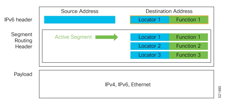

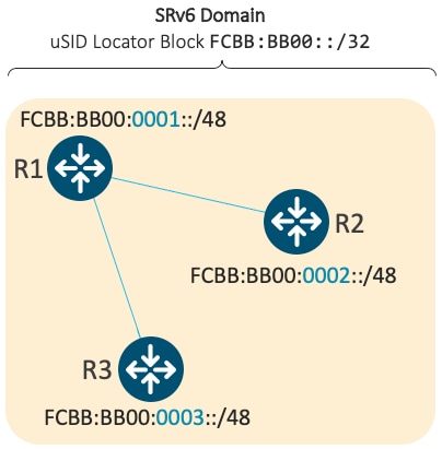
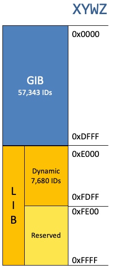


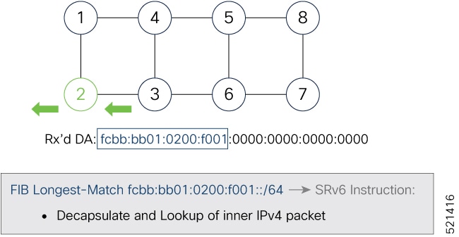


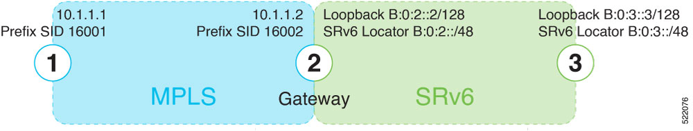


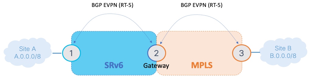

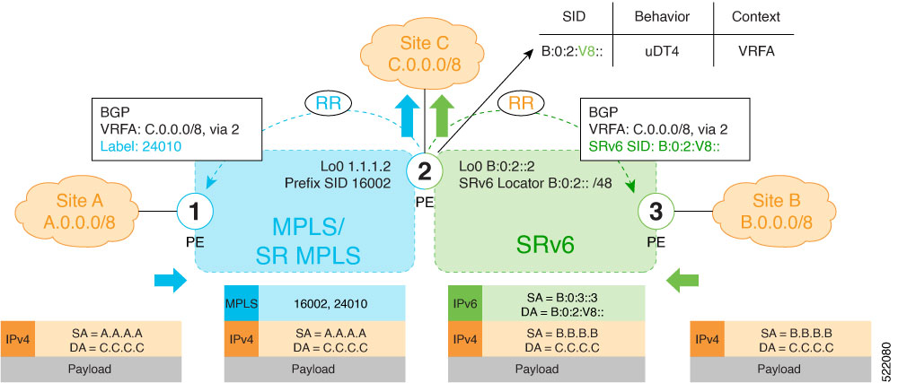


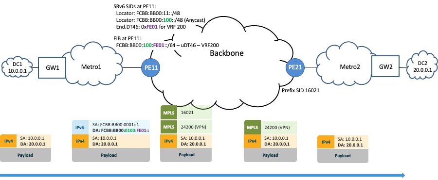


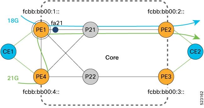
 Feedback