Overview

Overview

The Cisco HX C220 M6 node is a one-rack unit node that can be used standalone, or as part of the Cisco Unified Computing System, which unifies computing, networking, management, virtualization, and storage access into a single integrated architecture. Cisco HX also enables end-to-end node visibility, management, and control in both bare metal and virtualized environments. Each Cisco HX C220 M6 node supports:

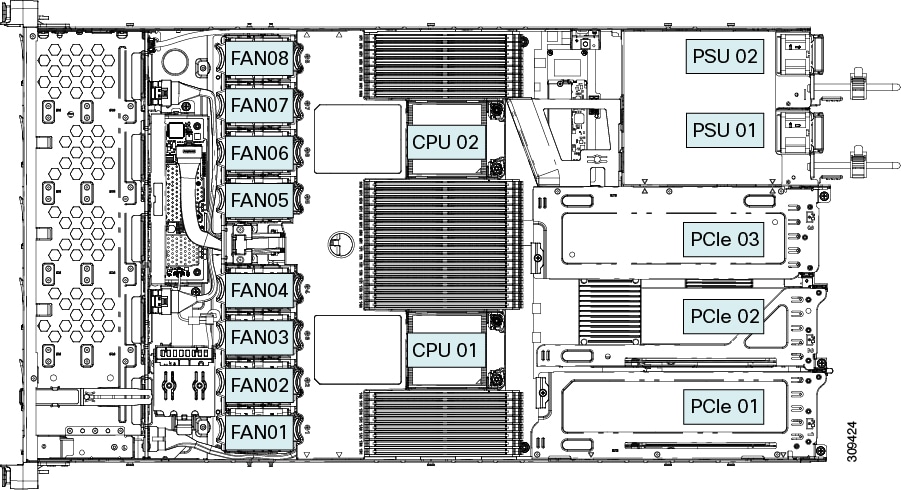
  • a maximum of two 3rd Generation Intel Xeon processors.

  • 32 DDR4 DIMMs (16 per CPU) for a total system memory of either 8 TB (32 256 GB DDR4 DIMMs) or 12 TB (16 x 256 GB DDR4 DIMMs1 and 16 x 512 GB Intel® Optane™ Persistent Memory Module.

    (PMEMs)).

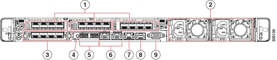
  • 3 PCI Express riser connectors, which provide slots for “full height” and “half height” PCI-e adapters.

  • Two Titanium (80 PLUS rated) power supplies with support for N and N+1 power redundancy modes.

  • 2 10GBase-T Ethernet LAN over Motherboard (LOM) ports for network connectivity, plus one 1 Gigabit Ethernet dedicated management port

  • One mLOM/VIC card provides 10G/25G/40G/50G/100G connectivity. Supported cards are:

    • Cisco HX VIC 15428 Quad Port CNA MLOM (HX-M-V5Q50G) supports:

      • a x16 PCIe Gen4 Host Interface to the rack node

      • four 10G/25G/50G SFP56 ports

      • 4GB DDR4 Memory, 3200 MHz

      • Integrated blower for optimal ventilation

    • Cisco HX VIC 1467 Quad Port 10/25G SFP28 mLOM (HX-M-V25-04) supports:

      • a x16 PCIe Gen3 Host Interface to the rack node

      • four 10G/25G QSFP28 ports

      • 2GB DDR3 Memory, 1866 MHz

    • Cisco HX VIC 1477 Dual Port 40/100G QSFP28 (HX-M-V100-04)

      • a x16 PCIe Gen3 Host Interface to the rack node

      • two 10G/25G QSFP28 ports

      • 2GB DDR3 Memory, 1866 MHz

  • One KVM port on the front of the node.

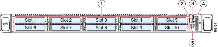
  • Two different front-loading hardware configurations are available:

    • The Cisco HX C220 M6 SFF (HX-C220-M6S): This model supports only small form-factor (SFF) drives and has a 10-drive backplane. Supports up to 10 front-loading 2.5-inch SAS/SATA drives, and up to 4 of the drives can be NVMe.

    • The Cisco HX C220 M6 NVMe (HX-C220-M6N): This model supports only small form-factor (SFF) drives and has a 10-drive backplane. Supports up to 10 front-loading 2.5-inch NVMe-only SSDs.

  • Rear PCI risers are supported as one to three half-height PCIe risers, or one to two full-height PCIe risers.

  • The node provides an internal slot for one of the following:

    • SATA Interposer to control SATA drives from the PCH (AHCI), or

    • Cisco 12G RAID controller with cache backup to control SAS/SATA drives, or

    • Cisco 12G SAS pass-through HBA to control SAS/SATA drives

External Features

This topic shows the external features of the server versions.

Cisco UCS C220 M6 Server Front Panel Features

The following figure shows the front panel features of the small form-factor drive versions of the server.

For definitions of LED states, see Front-Panel LEDs.

Figure 1. Cisco UCS C220 M6 Server Front Panel

1

Drive bays 1 – 10 support SAS/SATA hard disk drives (HDDs) and solid-state drives (SSDs). As an option, drive bays 1-4 can contain up to 4 NVMe drives in any number up to 4. Drive bays 5 through 10 support only SAS/SATA HDDs or SSDs.

NVMe drives are supported in a dual CPU server only.

2

Unit identification button/LED

3

Power button/power status LED

4

KVM connector

(used with KVM cable that provides one DB-15 VGA, one DB-9 serial, and two USB 2.0 connectors)

5

System LED cluster:

  • Fan status LED

  • System status LED

  • Power supply status LED

  • Network link activity LED

  • Temperature status LED

For more information, see Front-Panel LEDs

-

Cisco UCS C220 M6 Server Rear Panel Features

The rear panel features can be different depending on the number and type of PCIe cards in the server.

By default, single CPU servers come with only one half-height riser 1 installed, and dual CPU servers support all three half-height risers.

Rear PCIe risers can be one of the following configurations:

  • Half-height risers:

    • one half-height, ¾ length riser (not shown). With this configuration, PCIe slot (slot 1) supports one half-height, ¾ length, x16 lanes PCIe card and is controlled by CPU 1.

    • three half-height, ¾ length risers. See "UCS C220 M6 Server Rear Panel, Half Height, ¾ Length PCIe Cards" below.

  • Full-height risers: Two full height, ¾ length risers. See "Cisco UCS C220 M6 Server Rear Panel, Full Height, ¾ Length PCIe Cards" below.


Note

For definitions of LED states, see Rear-Panel LEDs.


Figure 2. Cisco UCS C220 M6 Server Rear Panel, Half Height, ¾ Length PCIe Cards

1

PCIe slots, three

This configuration accepts three card in riser slots 1, 2, and 3 as follows:

  • Riser 1, which is controlled by CPU 1:

    • Supports one PCIe slot (slot 1)

    • Slot 1 is half-height, 3/4 length, x16

  • Riser 2, which is controlled by CPU 1:

    • Supports one PCIe slot (slot 2)

    • Slot 2 is half-height, 3/4 length, x16

  • Riser 3, which is controlled by CPU 2:

    • Supports one PCIe slot (slot 3)

    • Slot 3 is half-height, 3/4 length, x16

2

Power supply units (PSUs), two which can be redundant when configured in 1+1 power mode.

3

Modular LAN-on-motherboard (mLOM) card bay (x16 PCIe lane)

USB 3.0 ports (two)

4

System identification button/LED

5

USB 3.0 ports (two)

6

Dual 1-Gb/10-Gb Ethernet ports (LAN1 and LAN2)

The dual LAN ports can support 1 Gbps and 10 Gbps, depending on the link partner capability.

7

1-Gb Ethernet dedicated management port

8

COM port (RJ-45 connector)

9

VGA video port (DB-15 connector)

Figure 3. Cisco UCS C220 M6 Server Rear Panel, Full Height, ¾ Length PCIe Cards

1

PCIe slots, two

This configuration accepts two cards in riser slots 1 and 2 as follows:

  • Riser 1, which is controlled by CPU 1:

    • Plugs into riser 1 motherboard connector

    • Supports one full-height, 3/4 length, x16 PCIe card

  • Riser 2, which is controlled by CPU 2:

    • Plugs into riser 3 motherboard connector

    • Supports one full-height, 3/4 length, x16 PCIe card

2

Power supply units (PSUs), two which can be redundant when configured in 1+1 power mode.

3

Modular LAN-on-motherboard (mLOM) card bay (x16 PCIe lane)

4

Unit identification button/LED

5

USB 3.0 ports (two)

6

Dual 1-Gb/10-Gb Ethernet ports (LAN1 and LAN2)

The dual LAN ports can support 1 Gbps and 10 Gbps, depending on the link partner capability.

7

1-Gb Ethernet dedicated management port

8

COM port (RJ-45 connector)

9

VGA video port (DB-15 connector)

Serviceable Component Locations

This topic shows the locations of the field-replaceable components and service-related items. The view in the following figure shows the node with the top cover removed.

Figure 4. Cisco HX C220 M6 node, Full Height, Full Width PCIe Cards, Serviceable Component Locations

1

Front-loading drive bays 1–10 support SAS/SATA drives.

2

M6 modular RAID card or SATA Interposer card

3

Cooling fan modules, eight.

Each fan is hot-swappable

4

SuperCap module mounting bracket

The SuperCap module (not shown) that mounts into this location provides RAID write-cache backup.

5

DIMM sockets on motherboard, 32 total, 16 per CPU

Eight DIMM sockets are placed between the CPUs and the node sidewall, and 16 DIMM sockets are placed between the two CPUs.

6

Motherboard CPU socket two (CPU2)

7

M.2 module connector

Supports a boot-optimized RAID controller with connectors for up to two SATA M.2 SSDs

8

Power Supply Units (PSUs), two

9

PCIe riser slot 2

Accepts 1 full height, full width PCIe riser card.

Includes PCIe cable connectors for front-loading NVMe SSDs (x8 lane)

10

PCIe riser slot 1

Accepts 1 full height, full width (x16 lane) PCIe riser card

11

Modular LOM (mLOM) card bay on chassis floor (x16 PCIe lane)

The mLOM card bay sits below PCIe riser slot 1.

12

Motherboard CPU socket one (CPU1)

13

Front Panel Controller board

The view in the following figure shows the individual component locations and numbering, including the FHFW PCIe cards.

Figure 5. Cisco HX C220 M6 node, Full Height, Full Width PCIe Cards, Serviceable Component Locations

1

Front-loading drive bays 1–10 support SAS/SATA drives.

2

M6 modular RAID card or SATA Interposer card

3

Cooling fan modules, eight.

Each fan is hot-swappable

4

SuperCap module mounting bracket

The SuperCap module (not shown) that mounts into this location provides RAID write-cache backup.

5

DIMM sockets on motherboard, 32 total, 16 per CPU

Eight DIMM sockets are placed between the CPUs and the node sidewall, and 16 DIMM sockets are placed between the two CPUs.

6

Motherboard CPU socket

CPU2 is the top socket.

7

M.2 module connector

Supports a boot-optimized RAID controller with connectors for up to two SATA M.2 SSDs

8

Power Supply Units (PSUs), two

9

PCIe riser slot 3

Accepts 1 half height, half width PCIe riser card.

10

PCIe riser slot 2

Accepts 1 half height, half width PCIe riser card.

11

PCIe riser slot 1

Accepts 1 half height, half width PCIe riser card

12

Modular LOM (mLOM) card bay on chassis floor (x16 PCIe lane)

The mLOM card bay sits below PCIe riser slot 1.

13

Motherboard CPU socket

CPU1 is the bottom socket

14

Front Panel Controller board

The view in the following figure shows the individual component locations and numbering, including the HHHL PCIe slots.

The Technical Specifications Sheets for all versions of this node, which include supported component part numbers, are at Cisco HyperFlex M6 Technical Specifications Sheets (scroll down to Technical Specifications).

Summary of Node Features

The following table lists a summary of features.

Feature

Description

Chassis

One rack-unit (1RU) chassis

Central Processor

Up to two 3rd Generation Intel Xeon processors.

Memory

32 slots for registered DIMMs (RDIMMs), DDR4 DIMMs, 3DS DIMMs, and load-reduced DIMMs (LR DIMMs) up to 3200 MHz. Also supported is Intel® Optane™ Persistent Memory Modules (PMEMs)

Multi-bit error protection

This supports multi-bit error protection.

Video

The Cisco Integrated Management Controller (CIMC) provides video using the Matrox G200e video/graphics controller:

  • Integrated 2D graphics core with hardware acceleration

  • DDR3 memory interface supports up to 512 MB of addressable memory (8 MB is allocated by default to video memory)

  • Supports display resolutions up to 1920 x 1200 16bpp @ 60Hz

  • High-speed integrated 24-bit RAMDAC

  • Single lane PCI-Express host interface running at Gen 2 speed

Network and management I/O

Rear panel:

  • One 1-Gb Ethernet dedicated management port (RJ-45 connector)

  • Two 1-Gb/10-Gb BASE-T Ethernet LAN ports (RJ-45 connectors)

    The dual LAN ports can support 10 Gbps, 1 Gbps, 100 Mbps, or 10 Mbps. The LAN ports autonegotiate to the correct link speed based on the link partner capability.

  • One RS-232 serial port (RJ-45 connector)

  • One VGA video connector port (DB-15 connector)

  • Two USB 3.0 ports

Front panel:

  • One front-panel keyboard/video/mouse (KVM) connector that is used with the KVM breakout cable. The breakout cable provides two USB 2.0, one VGA, and one DB-9 serial connector.

Modular LOM

One dedicated socket (x16 PCIe lane) that can be used to add an mLOM card for additional rear-panel connectivity. As an optional hardware configuration, the Cisco CNIC mLOM module supports two 100G QSFP+ ports or 4 25 Gbps Ethernet ports.

Power

Up to two of the following hot-swappable power supplies:

  • 1050 W (AC)

  • 1050 W (DC)

  • 1600 W (AC)

  • 2300 W (AC)

One power supply is mandatory; one more can be added for 1 + 1 redundancy.

ACPI

The advanced configuration and power interface (ACPI) 4.0 standard is supported.

Front Panel

The front panel provides status indications and control buttons

Cooling

Eight hot-swappable fan modules for front-to-rear cooling.

InfiniBand

In addition to Fibre Channel, Ethernet and other industry-standards, the PCI slots in this support the InfiniBand architecture up HDR IB (200Gbps).

Expansion Slots

Three half-height riser slots

  • Riser 1 (controlled by CPU 1): One x16 PCIe Gen4 Slot, (Cisco VIC), half-height, 3/4 length

  • Riser 2 (controlled by CPU 1): One x16 PCIe Gen4 Slot, half-height, 3/4 length

  • Riser 3 (controlled by CPU 2): One x16 PCIe Gen4 Slot, (Cisco VIC), half-height, 3/4 length

Two full-height riser slots

  • Riser 1 (controlled by CPU 1): One x16 PCIe Gen4 Slot,, full-height, 3/4 length

  • Riser 2 (controlled by CPU 2): One x16 PCIe Gen4 Slot, full-height, 3/4 length

Interfaces

Rear panel:

  • One 1Gbase-T RJ-45 management port

  • Two 10Gbase-T LOM ports

  • One RS-232 serial port (RJ45 connector)

  • One DB15 VGA connector

  • Two USB 3.0 port connectors

  • One flexible modular LAN on motherboard (mLOM) slot that can accommodate various interface cards

Front panel:

  • One KVM console connector, which supplies the pins for a KVM break out cable that supports the following:

    • Two USB 2.0 connectors

    • One VGA DB15 video connector

    • One serial port (RS232) RJ45 connector

Integrated Management Processor

Baseboard Management Controller (BMC) running Cisco Integrated Management Controller (CIMC) firmware.

Depending on your CIMC settings, the CIMC can be accessed through the 1GE dedicated management port, the 1GE/10GE LOM ports, or a Cisco virtual interface card (VIC).

CIMC supports managing the entire platform, as well providing management capabilities for various individual subsystems and components, such as PSUs, Cisco VIC, GPUs, MRAID and HBA storage controllers, and so on.

Storage Controllers

The SATA Interposer board, Cisco 12G SAS RAID Controller with 4GB FBWC, or Cisco 12G SAS HBA. Only one of these at a time can be used.

A Cisco 9500-8e 12G SAS HBA can be plugged into available PCIe risers for external JBOD attach. This HBA can be used at the same time as one of the other storage controllers.

  • SATA Interposer board: AHCI support of up to eight SATA-only drives (slots 1-4 and 6-9 only)

  • Cisco 12G RAID controller

    • RAID support (RAID 0, 1, 5, 6, 10) and SRAID0

    • Supports up to 10 front-loading SFF drives

  • Cisco 12G SAS HBA

    • No RAID support

    • JBOD/Pass-through Mode support

    • Supports up to 10 SFF front-loading SAS/SATA drives

  • Cisco 12G 9500-8e SAS HBA

    • No RAID support

    • Supports external JBOD attach (supports up to 1024 SAS/SATA devices or 32 NVMe devices)

    • Plugs into an appropriate PCIe riser slot (up to two supported)

For a detailed list of storage controller options, see Supported Storage Controllers and Cables. .

Modular LAN over Motherboard (mLOM) slot

The dedicated mLOM slot on the motherboard can flexibly accommodate the following cards:

  • Cisco Virtual Interface Cards (VICs)

  • Quad Port Intel i350 1GbE RJ45 Network Interface Card (NIC)

Note 

The four Intel i350 ports are provided on an optional card that plugs into the mLOM slot, and are separate from the two embedded (on the motherboard) LAN ports

UCSM

Unified Computing System Manager (UCSM) runs in the Fabric Interconnect and automatically discovers and provisions some of the components.