Cisco Nexus Dashboard Hardware Setup Guide for UCS-C220-M5 Servers
Bias-Free Language
The documentation set for this product strives to use bias-free language. For the purposes of this documentation set, bias-free is defined as language that does not imply discrimination based on age, disability, gender, racial identity, ethnic identity, sexual orientation, socioeconomic status, and intersectionality. Exceptions may be present in the documentation due to language that is hardcoded in the user interfaces of the product software, language used based on RFP documentation, or language that is used by a referenced third-party product. Learn more about how Cisco is using Inclusive Language.
Cisco Nexus Dashboard provides a common platform for deploying Cisco Data Center applications. These applications provide
real time analytics, visibility and assurance for policy and infrastructure.
The Cisco Nexus Dashboard server is required for installing and hosting the Cisco Nexus Dashboard application.
The server is orderable in the following version:
SE-CL-L3 — Small form-factor (SFF) drives, with 10-drive backplane. Supports up to 10 2.5-inch SAS/SATA drives. Drive bays
1 and 2 support NVMe SSDs.
External Features
This topic shows the external features of the server versions.
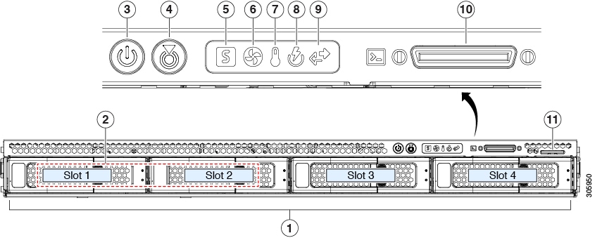
Cisco SE-CL-L3 (SFF Drives) Front Panel Features
The following figure shows the front panel features of the small form-factor drive versions of the server.
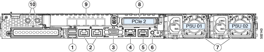
The dual LAN ports can support 1 Gbps and 10 Gbps, depending on the link partner capability.
These correspond to eth1-1 (eth0) and eth1-2 (eth1) respectively.
7
Power supplies (two, redundant as 1+1)
3
VGA video port (DB-15 connector)
8
PCIe riser 1/slot 1 (x16 lane)
Includes PCIe cable connectors for front-loading NVMe SSDs (x8 lane)
4
1-Gb Ethernet dedicated management port
9
Quad 10-Gb/25-Gb ports.
These correspond to eth 2-1 to eth 2-4. Only 2 interfaces out of the 4 are active at a time (eth2-1/2-2 or eth2-3/2-4) in active/standby mode.
5
Serial port (RJ-45 connector)
10
Threaded holes for dual-hole grounding lug
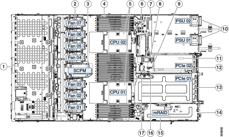
Serviceable Component Locations
This topic shows the locations of the field-replaceable components and service-related items. The view in the following figure
shows the server with the top cover removed.
Front-loading drive bays 1–10 support SAS/SATA drives.
SE-CL-L3 : Drive bays 1 and 2 support NVMe PCIe SSDs.
10
Power supplies (hot-swappable when redundant as 1+1)
2
Cooling fan modules (seven, hot-swappable)
11
Trusted platform module (TPM) socket on motherboard (not visible in this view)
3
Supercap unit mounting bracket (RAID backup)
12
PCIe riser 2/slot 2 (half-height, x16 lane)
Includes PCIe cable connectors for front-loading NVMe SSDs (x8 lane)
4
DIMM sockets on motherboard (12 per CPU)
13
PCIe riser 1/slot 1 (full-height, x16 lane)
Includes socket for Micro-SD card
5
CPUs and heatsinks (up to two)
14
Modular LOM (mLOM) card bay on chassis floor (x16 PCIe lane), not visible in this view
6
Mini-storage module socket. Options:
SD card module with two SD card slots
M.2 module with slots for either two SATA M.2 drives or two NVMe M.2 drives
Cisco Boot-Optimized M.2 RAID Controller (module with two slots for SATA M.2 drives, plus an integrated SATA RAID controller
that can control the two M.2 drives in a RAID 1 array)
15
Modular RAID (mRAID) riser, can optionally be a riser that supports either:
Hardware RAID controller card
Interposer card for embedded SATA RAID
7
Chassis intrusion switch (optional)
16
PCIe cable connectors for front-loading NVMe SSDs on PCIe riser 2
8
Internal USB 3.0 port on motherboard
17
Micro-SD card socket on PCIe riser 1
9
RTC battery, vertical socket
-
Summary of Server Features
The following table lists a summary of server features.
Feature
Description
Chassis
One rack-unit (1RU) chassis
Central Processor
Up to two CPUs from the Intel Xeon Processor Scalable Family. This includes CPUs from the following series:
Intel Xeon Silver 4XXX Processors
Memory
24 DDR4 DIMM sockets on the motherboard (12 each CPU)
Depending on your Cisco IMC settings, Cisco IMC can be accessed through the 1-Gb dedicated management port, the 1-Gb/10-Gb
Ethernet LAN ports, or a Cisco virtual interface card.
Network and management I/O
Rear panel:
One 1-Gb Ethernet dedicated management port (RJ-45 connector)
Two 1-Gb/10-Gb BASE-T Ethernet LAN ports (RJ-45 connectors)
The dual LAN ports can support 1 Gbps and 10 Gbps, depending on the link partner capability.
One RS-232 serial port (RJ-45 connector)
One VGA video connector port (DB-15 connector)
Two USB 3.0 ports
Front panel:
One front-panel keyboard/video/mouse (KVM) connector that is used with the KVM cable, which provides two USB 2.0, one VGA,
and one DB-9 serial connector.
Modular LOM
One dedicated socket (x16 PCIe lane) that can be used to add an mLOM card for additional rear-panel connectivity.
Power
One power supply:
AC power supplies 1050 W AC each
ACPI
The advanced configuration and power interface (ACPI) 4.0 standard is supported.
Cooling
Seven hot-swappable fan modules for front-to-rear cooling.
PCIe I/O
Two horizontal PCIe expansion slots on a PCIe riser assembly.
The PCIe bus slots in this server support the InfiniBand architecture.
Storage, front-panel
The server is orderable in three different versions, each with a different front panel/drive-backplane configuration.
SE-CL-L3 , Small form-factor (SFF) drives, with 10-drive backplane. Supports up to 10 2.5-inch SAS/SATA drives. Drive bays
1 and 2 support NVMe SSDs.
Storage, internal
The server has these internal storage options:
One USB port on the motherboard.
One micro-SD card socket on PCIe riser 1.
Mini-storage module socket, optionally with either:
SD card module. Supports up to two SD cards.
M.2 SSD module. Supports either two SATA M.2 SSDs or two NVMe M.2 SSDs.
Cisco Boot-Optimized M.2 RAID Controller (module with two slots for SATA M.2 drives, plus an integrated SATA RAID controller
that can control the two SATA M.2 drives in a RAID 1 array)
Storage management
The server has a dedicated internal mRAID riser that supports one of the following storage-controller options:
A PCIe-style Cisco modular RAID controller card (SAS/SATA).
A PCIe-style interposer card for the server’s embedded SATA RAID controller.

 Feedback