Tree Segment Identifier (Tree-SID) Multicast Traffic Engineering

Tree-SID is a method of implementing tree-like multicast flows over a segmented routing network. Using Tree-SID, an SDN controller (a device running SR-PCE using PCEP) calculates the tree. Each node (device) in the tree has a specific role in routing the multicast data through the tree. These roles include Ingress for the root or headend node, Transit or Bud for midpoint nodes that are not leaf nodes, and Egress for destination leaf nodes. The tree itself is assigned a single SID label, representing all of the tree segments and devices. The SDN controller is highly flexible, as it understands the segmentation and can construct routing paths using any constraints that network architects can specify.

The most interesting use case for constraint-based Tree-SID use is where routers are configured to deliver two P2MP streams with the same content over different paths. Here, the multicast flow is forwarded twice through the network, each copy following a unique path. The two copies never use the same node or link to reach the destination, reducing packet loss due to network failures on any one of the paths.

For detailed information on Tree-SID, see the Segment Routing Tree-SID configuration documentation for your specific device (for example, Segment Routing Configuration Guide for Cisco NCS 540 Series Routers).

This section contains the following topics.

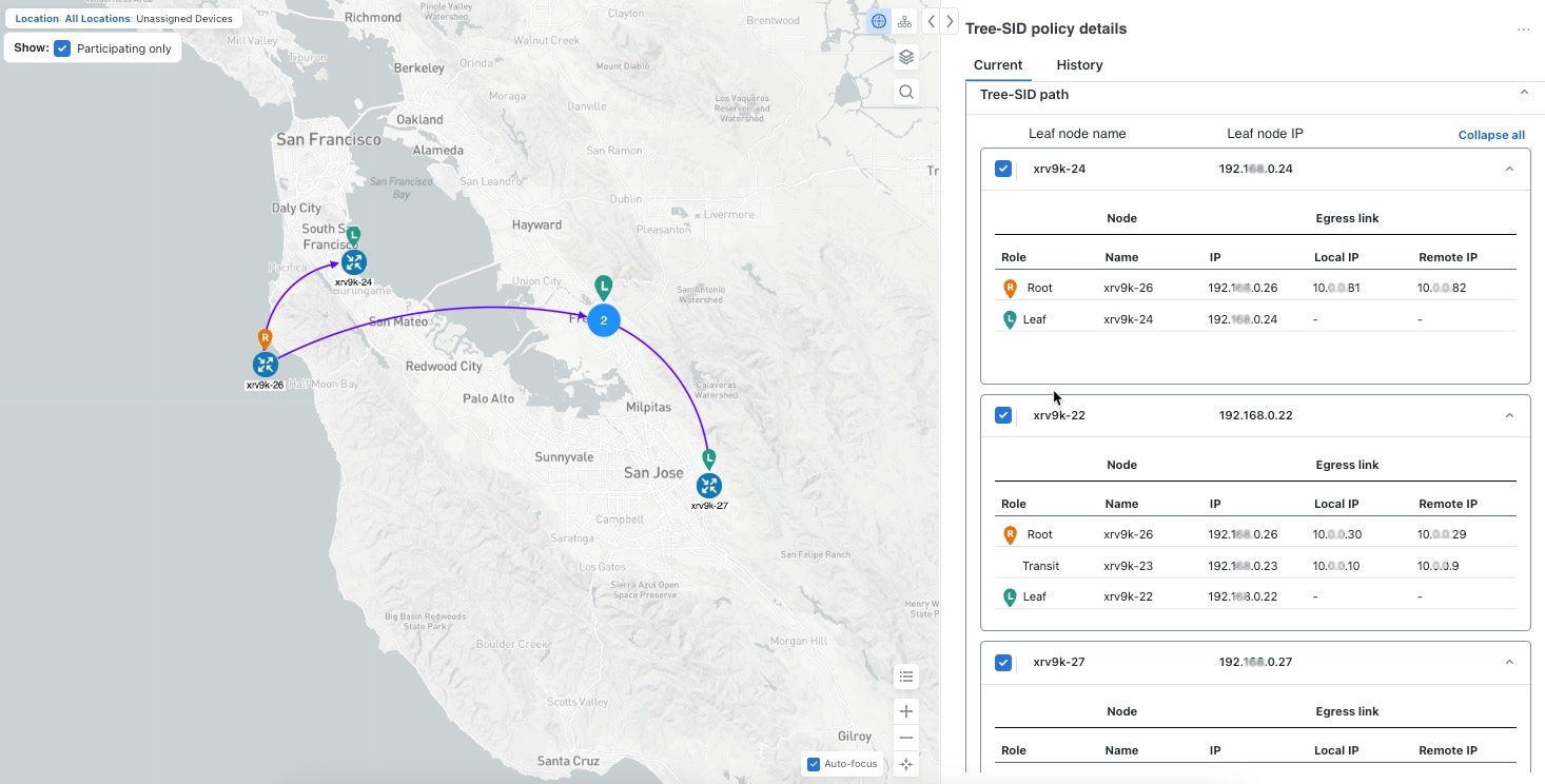
Visualize Tree-SID Policies

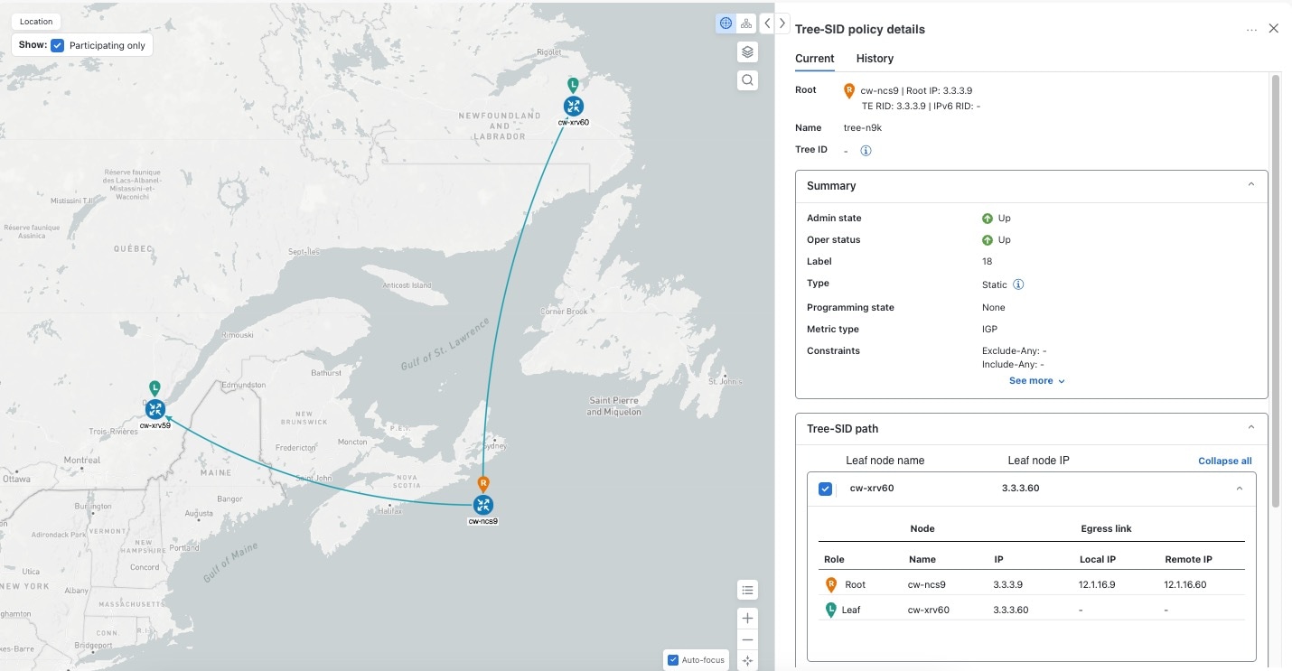
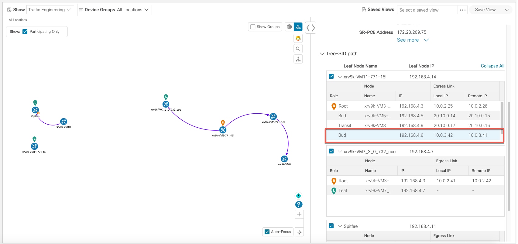
Crosswork UI provides the ability to view details of the Tree-SID root, transit, leaf nodes, and bud nodes in the UI and allows you to easily confirm that Tree-SID is implemented correctly in your network (see View a Point-to-Multipoint Tree on the Topology Map).

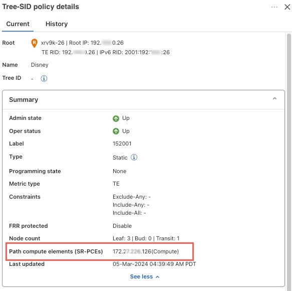
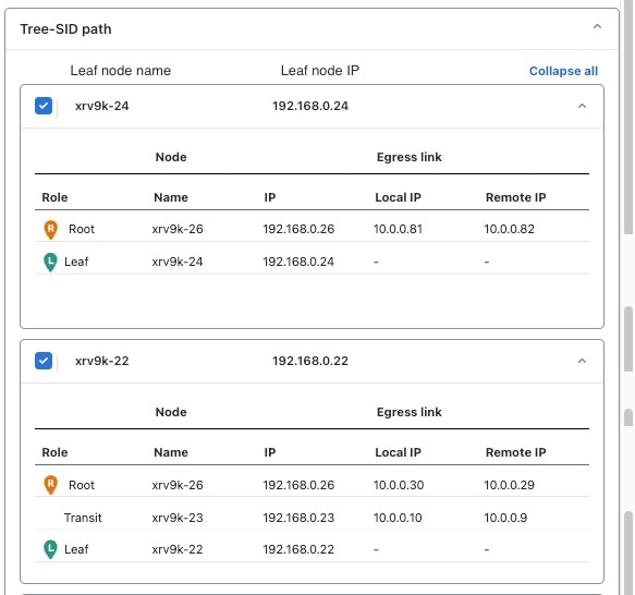
The Tree-SID policy has the following nodes:

  • Root node—Encapsulates the multicast traffic, replicates it, and forwards it to the transit nodes.

  • Transit node—Acts as a leaf (egress) node and a mid-point (transit) node toward the downstream sub-tree.

  • Leaf node—Decapsulates the multicast traffic and forwards it to the multicast receivers.

  • Bud Node—Has a separate leaf node path and is displayed separately in the topology map.

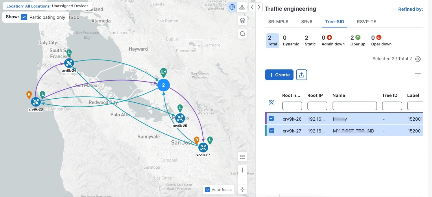
You can visualize the following Tree-SID policies:

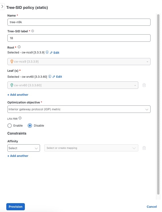
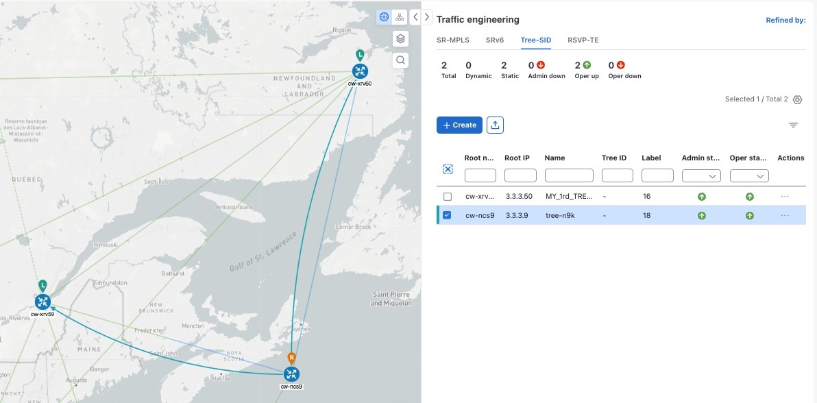
  • Static: A Static Tree-SID policy is configured via SR-PCE, directly using SR-PCE CLI or from the Crosswork UI. You can refer to the Tree-SID configuration documentation for your specific device for more information and examples of the supported configuration commands. (for example, Segment Routing Configuration Guide for Cisco ASR 9000 Series Routers

  • Dynamic: A Dynamic Tree-SID policy is not explicitly configured; it is configured as part of an L3VPN/ mVPN service.


Note


Static and Dynamic Tree-SID policies support fast reroute (FRR).


View a Point-to-Multipoint Tree on the Topology Map

Crosswork allows you to visualize Tree-SID policies configured in your network.

The following example shows a representation of a Tree-SID policy in the topology map. The root node (R) and leaf nodes (L) are marked, and the arrows denote the path through the transit nodes from the root to the leaf nodes.

Figure 1. Create a new Tree-SID Policy (static)

Create a new Tree-SID Policy (static)

Before you begin

To visualize a multicast tree in the topology map, Tree-SID policies must be configured in your network. For more information, see the SR Tree-SID configuration documentation for your specific device (for example, Segment Routing Configuration Guide for Cisco NCS 540 Series Routers).

Procedure


Step 1

From the main menu, select Traffic Engineering > Traffic Engineering > Tree-SID tab.

Step 2

Select the Tree-SID policies you want to view on the topology map. You can view a maximum of two policies on the topology map at the same time.

Figure 2. Tree-SID Policies (static) on the Topology Map

Tree-SID Policies (static) on the Topology Map

Note


Any change in end-points is captured as an event in the historical data tab. For information on Tree-SID Historical Data, see View TE Event and Utilization History

Step 3

To view Tree-SID details, from the Actions column, click More icon > View details for one of the Tree-SID policies. You will see a summary and Tree-SID path information.

Example:

Note

 
  • A (Compute) label, next to the SR-PCE field, details the SR-PCE used to create the policies.

  • If a source node is unavailable, a warning icon and message appear next to the Oper Status field (hover your mouse over the warning icon), detailing where the connection issue resides.

Figure 3. Tree-SID Details Summary

Tree-SID Details Summary
Figure 4. Tree-SID Path Details

Tree-SID Path Details

Create Static Tree-SID Policies

This task will explain how to create a static Tree-SID policy, each representing a leaf or a root node.


Tip


If you plan to use affinities, collect affinity information from your devices and map them in Cisco Crosswork before creating a static Tree-SID policy. For more information, see Configure TE Link Affinities.

Procedure


Step 1

From the main menu, choose Traffic Engineering > Traffic Engineering > Tree-SID tab and click Create.

Step 2

Enter or select the required Tree-SID policy values. Hover the mouse pointer over Field Help icon to view a description of the field.

Note


You can only add PCC nodes with a PCEP session to PCE as root nodes.

Figure 5. Create Static Tree-SID Policy

Create Static Tree-SID Policy

Step 3

To commit the policy, click Provision.

Step 4

Validate the Tree-SID policy creation:

  1. Confirm that the new Tree-SID policy appears in the Traffic engineering table. You can also click the check box next to the policy to see it highlighted in the map.

    Note

     
    The newly provisioned Tree-SID policy may take some time to appear in the Traffic engineering table, depending on the network size and performance. The Traffic engineering table is refreshed every 30 seconds.
    Figure 6. Newly Added Tree-SID Policy on Topology Map

    Newly Added Tree-SID Policy on Topology Map
  2. View and confirm the new Tree-SID policy details. From the Actions column, click More icon and select View details.

    Figure 7. Tree-SID Policy Details

    Tree-SID Policy Details

Static Tree-SID Policy Configuration Example through Crosswork UI

The output below shows the static Tree-SID policy, configured from Crosswork UI, on the compute SR-PCE.

RP/0/RP0/CPU0:cw-xrv56#sh pce lsp p2mp                                                                
 
Tree: 50-52-54, Root: 3.3.3.50 
 PCC: 3.3.3.50
 Label:   505254
 Operational: up  Admin: up  Compute: Yes
 Local LFA FRR: Disabled
 Metric Type: IGP
 Transition count: 1
 Uptime: 00:01:45 (since Thu Apr 27 10:54:49 PDT 2023)
 Destinations: 3.3.3.52, 3.3.3.54
 Nodes:
  Node[0]: 3.3.3.50 (cw-xrv50)
   Delegation: PCC
   PLSP-ID: 205
   Role: Ingress
   Hops:
    Incoming: 505254 CC-ID: 1
    Outgoing: 505254 CC-ID: 1 (11.1.28.54) [cw-xrv54]
    Outgoing: 505254 CC-ID: 1 (11.1.1.51) [cw-xrv51]
  Node[1]: 3.3.3.54 (cw-xrv54)
   Delegation: PCC
   PLSP-ID: 148
   Role: Egress
   Hops:
    Incoming: 505254 CC-ID: 2
  Node[2]: 3.3.3.51 (cw-xrv51)
   Delegation: PCC
   PLSP-ID: 187
   Role: Transit
   Hops:
    Incoming: 505254 CC-ID: 3
    Outgoing: 505254 CC-ID: 3 (11.1.2.52) [cw-xrv52]
  Node[3]: 3.3.3.52 (cw-xrv52)
   Delegation: PCC
   PLSP-ID: 247
   Role: Egress
   Hops:
    Incoming: 505254 CC-ID: 4
 

The output below shows the same static Tree-SID policy on the High Availability (HA) peer SR-PCE.

RP/0/RP0/CPU0:cw-xrv63#sh pce lsp p2mp
 
Tree: 50-52-54, Root: 3.3.3.50 
 PCC: 3.3.3.50
 Label:   505254
 Operational: standby  Admin: up  Compute: No
 Local LFA FRR: Disabled
 Metric Type: IGP
 Transition count: 0
 Destinations: 3.3.3.52, 3.3.3.54
 Nodes:
  Node[0]: 3.3.3.54 (cw-xrv54)
   Delegation: PCE (3.3.3.56)
   PLSP-ID: 148
   Role: Egress
   Hops:
    Incoming: 505254 CC-ID: 2
  Node[1]: 3.3.3.52 (cw-xrv52)
   Delegation: PCE (3.3.3.56)
   PLSP-ID: 247
   Role: Egress
   Hops:
    Incoming: 505254 CC-ID: 4
  Node[2]: 3.3.3.51 (cw-xrv51)
   Delegation: PCE (3.3.3.56)
   PLSP-ID: 187
   Role: Transit
   Hops:
    Incoming: 505254 CC-ID: 3
    Outgoing: 505254 CC-ID: 3 (11.1.2.52)
  Node[3]: 3.3.3.50 (cw-xrv50)
   Delegation: PCE (3.3.3.56)
   PLSP-ID: 205
   Role: Ingress
   Hops:
    Incoming: 505254 CC-ID: 1
    Outgoing: 505254 CC-ID: 1 (11.1.28.54)
    Outgoing: 505254 CC-ID: 1 (11.1.1.51)

Modify a Tree-SID Policy

To modify a Tree-SID policy, do the following:


Note


You cannot modify the name, label and root of a Tree-SID policy.


Procedure


Step 1

From the main menu, choose Traffic Engineering > Traffic Engineering > Tree-SID tab.

Step 2

Locate the Tree-SID policy you are interested in and click More icon.

Step 3

Choose Edit/Delete.

Note

 
  • You can only modify or delete a static Tree-SID policy that is created using the Crosswork UI or API as opposed to one created using SR-PCE CLI.

  • After updating the Tree-SID policy details, you can preview the changes on the map before saving it.


Tree-SID Important Notes

Limitation

  • Tree-SID policies are only supported on devices running Cisco IOS XR software.

  • PCE high-availability (HA) is supported for static Tree-SID policies configured via the Cisco Crosswork UI, but is not supported if configured directly on the SR-PCE CLI.

  • Tree-SID policy details based on SRv6 are not supported.

  • If a single instance of SR-PCE is used, and the SR-PCE restarts, all static Tree-SID policies that were configured from the Crosswork UI are deleted.

  • IPV4 unnumbered interfaces are not supported.

Visualization of Tree-SID Paths with Missing Nodes

Missing Tree-SID nodes can cause the following issues:

There may be instances where a node on a Tree-SID policy path is not available in the Crosswork topology information. This could happen if the node is not added to the Crosswork device inventory. This affects the display of the Tree-SID policy path on the topology map, causing one or more root-to-leaf paths to appear broken. However, the path details in the right panel will still show the full path.