Traffic Engineering in Cisco Crosswork Network Controller

Traffic engineering (TE) is a method of optimizing and steering traffic in a network to achieve an operational goal or provide custom services, such as using guaranteed bandwidth routes for prioritized traffic. TE improves network performance by forcing traffic to take predetermined routes and by using available resources effectively.

One of the biggest advantages of using Crosswork is the ability to visualize SR-TE policies and RSVP-TE tunnels on a topology map. By visually examining your network, the complexity of provisioning and managing these SR-TE policies is significantly reduced

The following table lists what Traffic Engineering SR policies and RSVP tunnels can be visualized and provisioned through the Crosswork UI.

For a list of known limitations, important notes, and what networking technologies are supported, see the Cisco Crosswork Network Controller Release Notes.

Table 1. Supported TE Technologies

TE Technology

Crosswork Network Controller

Visualize

Provision

SR-MPLS

Checkmark icon

Checkmark icon

SRv6

Checkmark icon

Checkmark icon

RSVP

Checkmark icon

Checkmark icon

Flexible Algorithms

Checkmark icon

Not Supported icon

Tree-SID

Checkmark icon

Checkmark icon

Circuit Style

Checkmark icon

Checkmark icon


Note


Users must be assigned admin roles or have certain Device Access Group permissions to provision and access some features. For more information on Role-based Access Control (RBAC) and user roles, see the "Cisco Crosswork Network Controller Administration Guide".


Segment Routing Path Computation Element (SR-PCE)

Cisco Crosswork uses the combination of telemetry and data that are collected from the Cisco Segment Routing Path Computation Element (SR-PCE) to analyze and compute optimal TE tunnels.

Cisco SR-PCE (formerly Cisco XR Traffic Controller (XTC)) runs on the Cisco IOS XR operating system. SR-PCE provides stateful PCE functionality that helps control and reroute TE tunnels to optimize the network. PCE describes a set of procedures by which a Path Computation Client (PCC) can report and delegate control of headend tunnels that are sourced from the PCC to a PCE peer. The PCC and PCE establish a Path Computation Element Communication Protocol (PCEP) connection that SR-PCE uses to push updates to the network.

Crosswork discovers all devices that are part of the IGP domain including those that do not establish PCEP peering with SR-PCE. However, PCEP peering is required to deploy TE tunnels to the device.


Note


Features may not work as expected if the SR-PCE version is not supported. It is important to refer to the Cisco Crosswork Network Controller Release Notes for SR-PCE version support and compatibility.

For SR-PCE and HA configuration, see the "Prepare Infrastructure for Device Management: Manage Providers" section in the Cisco Crosswork Network Controller Administration Guide.


What is Segment Routing?

Segment routing for traffic engineering takes place through a tunnel between a source and destination pair. Segment routing for traffic engineering uses the concept of source routing, where the source calculates the path and encodes it in the packet header as a segment. Segments are an identifier for any type of instruction. For example, topology segments identify the next hop toward a destination. Each segment is identified by the segment ID (SID) consisting of a unsigned 32-bit integer. Each segment is an end-to-end path from the source to the destination, and instructs the routers in the provider core network to follow the specified path instead of the shortest path calculated by the IGP. The destination is unaware of the presence of the tunnel.

Segments

Interior gateway protocol (IGP) distributes two types of segments: prefix segments and adjacency segments. Each router (node) and each link (adjacency) has an associated segment identifier (SID).

  • A prefix SID is associated with an IP prefix. The prefix SID is manually configured from the segment routing global block (SRGB) range of labels, and is distributed by IS-IS or OSPF. The prefix segment steers the traffic along the shortest path to its destination. A node SID is a special type of prefix SID that identifies a specific node. It is configured under the loopback interface with the loopback address of the node as the prefix.

    A prefix segment is a global segment, so a prefix SID is globally unique within the segment routing domain.

  • An adjacency segment is identified by a label called an adjacency SID, which represents a specific adjacency, such as egress interface, to a neighboring router. The adjacency SID is distributed by IS-IS or OSPF. The adjacency segment steers the traffic to a specific adjacency.

    An adjacency segment is a local segment, so the adjacency SID is locally unique relative to a specific router.

By combining prefix (node) and adjacency segment IDs in an ordered list, any path within a network can be constructed. At each hop, the top segment is used to identify the next hop. Segments are stacked in order at the top of the packet header. When the top segment contains the identity of another node, the receiving node uses equal cost multipaths (ECMP) to move the packet to the next hop. When the identity is that of the receiving node, the node pops the top segment and performs the task required by the next segment.

Segment Routing Policies

Segment routing for traffic engineering uses a “policy” to steer traffic through the network. An SR policy path is expressed as a list of segments that specifies the path, called a segment ID (SID) list. Each segment is an end-to-end path from the source to the destination, and instructs the routers in the network to follow the specified path instead of the shortest path calculated by the IGP. If a packet is steered into an SR policy, the SID list is pushed on the packet by the head-end. The rest of the network executes the instructions embedded in the SID list.

Crosswork supports the visualization (and some provisioning) of the following SR-related policies:


Note


Crosswork discovers existing SR policies when devices are imported, but cannot manage them. SR policies can be managed only if they were provisioned using the UI.


There are two types of SR policies: dynamic and explicit.

Dynamic SR Policy

A dynamic path is based on an optimization objective and a set of constraints. The head-end computes a solution, resulting in a SID list or a set of SID lists. When the topology changes, a new path is computed. If the head-end does not have enough information about the topology, the head-end might delegate the computation to a path computation engine (PCE).

Explicit SR Policy

When you configure an explicit policy, you specify an explicit path which consists of a list of prefix or adjacency SIDs, each representing a node or link along on the path.

Disjointness

Crosswork uses the disjoint policy to compute two lists of segments that steer traffic from two source nodes to two destination nodes along disjoint paths. The disjoint paths can originate from the same head-end or different head-ends. Disjoint level refers to the type of resources that should not be shared by the two computed paths. The following disjoint path computations are supported:

  • Link – Specifies that links are not shared on the computed paths.

  • Node – Specifies that nodes are not shared on the computed paths.

  • SRLG – Specifies that links with the same Share Risk Link Group (SRLG) value are not shared on the computed paths.

  • SRLG-node – Specifies that SRLG and nodes are not shared on the computed paths.

When the first request is received with a given disjoint-group ID, a list of segments is computed, encoding the shortest path from the first source to the first destination. When the second request is received with the same disjoint-group ID, information received in both requests is used to compute two disjoint paths: one path from the first source to the first destination, and another path from the second source to the second destination. Both paths are computed at the same time. The shortest lists of segments is calculated to steer traffic on the computed paths.


Note


  • Disjointness is supported for two policies with the same disjoint ID.

  • Configuring affinity and disjointness at the same time is not supported.


SR-TE Policy PCC and PCE Configuration Sources

SR-TE policies discovered and reported by Crosswork may have been configured from the following sources:

  • Path Computation Client (PCC) initiated—Policies configured on a PCC (see PCC-Initiated SR-TE Policy Example). This policy type displays as Unknown in the UI.

  • Path Computation Element (PCE) initiated—Policies configured on a PCE or created dynamically by Crosswork. PCE Initiated policy types can be one of the following:

    • Dynamic

    • Explicit

    • Circuit-Style

    • Bandwidth on Demand

    • Local Congestion Mitigation


Note


SR policies that are configured using the UI are the only types of SR-TE policies that you can modify or delete in Crosswork.


PCC-Initiated SR-TE Policy Example

The following example shows a configuration of an SR-TE policy at the headend router. The policy has a dynamic path with affinity constraints computed by the headend router. See SR configuration documentation for your specific device to view descriptions and supported configuration commands (for example: Segment Routing Configuration Guide for Cisco ASR 9000 Series Routers).

segment-routing
 traffic-eng
  policy foo
   color 100 end-point ipv4 1.1.1.2
   candidate-paths
    preference 100
     dynamic
      metric
       type te
      !
     !
     constraints
      affinity
       exclude-any
        name RED
       !
      !
     !
    !
   !

What is Resource Reservation Protocol (RSVP)?

Resource Reservation Protocol (RSVP) is a signaling protocol that enables systems to request resource reservations from the network. RSVP processes protocol messages from other systems, processes resource requests from local clients, and generates protocol messages. As a result, resources are reserved for data flows on behalf of local and remote clients. RSVP creates, maintains, and deletes these resource reservations.

The RSVP-TE process contains the following functionalities:

  • Endpoint control, which is associated with establishing and managing TE tunnels at the headend and tail end.

  • Link-management, which manages link resources to do resource-aware routing of TE Label-Switched Path (LSP) and to program MPLS labels.

  • Fast Reroute (FRR), which manages the LSPs that need protection and assigns backup tunnel information to these LSPs.

The interactions between TE and RSVP assume the existence of the endpoint control, link-management, and FRR functionality within TE.

RSVP-TE Explicit Routing (Strict, Loose)

RSVP-TE explicit routes are particular paths in the network topology that you can specify as abstract nodes, which could be a sequence of IP prefixes or a sequence of autonomous systems, in the Explicit Route Object (ERO). The explicit path can be administratively specified, or automatically computed using an algorithm such as constrained shortest path first (CSPF).

The explicit path that is specified in the ERO could be a strict path or a loose path.

A strict path means that a network node and its preceding node in the ERO must be adjacent and directly connected.

A loose hop means that a network node specified in the ERO must be in the path but is not required to be directly connected to its preceding node. If a loose hop is encountered during ERO processing, the node that processes the loose hop can update the ERO with one or more nodes along the path from itself to the next node in the ERO. The advantage of a loose path is that the entire path does not need to be specified or known when creating the ERO. The disadvantage of a loose path is that it can result in forwarding loops during transients in the underlying routing protocol.


Note


RSVP-TE tunnels cannot be configured with loose hops when provisioning within the UI.


RSVP FRR

When a router’s link or neighboring device fails, the router often detects this failure by receiving an interface-down notification. When a router notices that an interface has gone down, it switches LSPs going out that interface onto their respective backup tunnels (if any).

The FRR object is used in the PATH message and contains a flag that identifies the backup method to be used as facility-backup. The FRR object specifies setup and hold priorities, which are included in a set of attribute filters and bandwidth requirements to be used in the selection of the backup path.

The Record Route Object (RRO) reports in the RESV message the availability or use of local protection on an LSP, and whether bandwidth and node protection are available for that LSP.

The signaling of the FRR requirements is initiated at the TE tunnel headend. Points of Local Repair (PLR) along the path act on the FRR requirements based on the backup tunnel availability at the PLR, and signal the backup tunnel selection information to the headend. When an FRR event is triggered, the PLR sends PATH messages through the backup tunnel to the merge point (MP) where the backup tunnel rejoins the original LSP. The MP also sends RESV messages to the PLR using the RSVP-Hop object that is included by the PLR in its PATH message. This process prevents the original LSP from being torn down by the MP. Also, the PLR signals the tunnel headend with a PATH-ERROR message to indicate the failure along the LSP and that FRR is in active use for that LSP. This information is used by the headend to signal a new LSP for the TE tunnel, and to tear down the existing failed path after the new LSP is set up through make-before-break techniques.

RSVP-TE Tunnel PCC and PCE Configuration Sources

RSVP-TE tunnels discovered and reported by Crosswork may have been configured from the following sources:

  • Path Computation Client (PCC) initiated—RSVP-TE tunnels configured on a PCC (see PCC-Initiated RSVP-TE Tunnel Example).

  • Path Computation Element (PCE) or PCC initiated dynamically.

Get a Quick View of Traffic Engineering Services

The TE Dashboard provides a high-level summary of RSVP-TE tunnel, SR-MPLS, SRv6, and Tree-SID policy information.

To get to the TE Dashboard, choose Services & Traffic Engineering > TE Dashboard.


Note


If you are viewing the HTML version of this guide, click the images to view them in full-size.


Callout No. Description

1

Traffic Engineering Dashlet: Displays the total policy count and count of policies according to the policy state.

It also displays the number of all TE policies and the number of policies/tunnel according to the metric types for all TE services.

To drill down for more information, click on a value. The topology map and TE table appear displaying only the filtered data that you clicked on.

2

Policies and Tunnels Under Traffic Threshold:

Displays RSVP-TE tunnels and SR-MPLS policies that have traffic below the defined threshold in the selected time period. This information may be used to find and filter the unused policies or tunnels. Click to update the underutilized LSP threshold value.

Note


Traffic utilization is not captured for SRv6 and Tree-SID policies.

3

Allows you to filter the data on the dashlet based on the time range you want to view (date, 1 month, 1 week, 1 day, and 1 hour).

4

Policy and Tunnel Change Events: Displays all the policies and tunnels that have had a path or state change event ordered by the event count, within the selected time range. This information helps identify the unstable policies and tunnels.

Note


The addition or deletion of leaf nodes for Tree-SID policies is captured as events.


Note


For a list of known limitations, see the Cisco Crosswork Network Controller Release Notes.


View TE Event and Utilization History

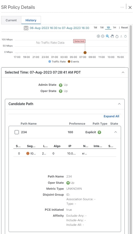
The historical data captures the traffic rate and change events for a policy or tunnel. To view the historical data:


Note


Traffic Rate is not captured for SRv6 and Tree-SID policies.


Procedure


Step 1

From the main menu, choose Services & Traffic Engineering > Traffic Engineering.

Step 2

From the Actions column of the Traffic Engineering table, click More icon > View Details > History tab tab for a policy or tunnel. The tab displays associated historical data for that device. Click on the event to see the path or state change event information.


View Traffic Engineering Device Details

To view Traffic Engineering Device details (SR-MPLS, SRv6, RSVP-TE, and Flexible Algorithm information), do the following:

Procedure


Step 1

From the main menu, choose Services & Traffic Engineering > Traffic Engineering.

Step 2

From the Traffic Engineering topology map, click on a device.

Step 3

From the Traffic Engineering tab, click on the policy type you are interested in. Each tab displays associated data for that device. From the browser, you can copy the URL and share with others.

The following example shows the Tree-SID information details for the selected device.

Note


If you are viewing the HTML version of this guide, click on the image to view it in full-size.


Configure Traffic Engineering Settings

Configure TE Timeout Settings

To configure timeout settings for the provisioning and retrieval of data for SR-TE policies, RSVP-TE tunnels, Bandwidth on Demand and IGP paths, select Administration > Settings > System Settings > Traffic Engineering > General Settings under the Advance Settings section. Enter the timeout duration options. For more information, click Field Help icon.


Note


Timeouts change the response time of each of the actions if SR-PCE is slow in responding. You can modify the settings for a large scale topology or to address slow SR-PCE response due to latency or load.


Configure How Device Groups Are Displayed for Traffic Engineering

You can configure what is shown on the topology map when a device group is selected and a device in the selected SR policy, service, or RSVP-TE tunnel does not belong in the group. To set the behavior, choose Administration > Settings > User Settings tab > Switch Device Group and select one of the behavior options.

By default, the user is asked each time to choose the device group view.

Configure Historical Data Settings

To configure the TE Dashboard (and Historical Data) settings for the collection of policy and tunnel metrics, state changes, path changes, data retention interval, and the utilization threshold for underutilized LSPs, select Administration > Settings > System Settings tab > Performance Monitoring & Analytics > Historical Data.

Table 2. Available Historical Data Setting Options
Historical Data Settings Description

LSP Traffic Rate

Turn on this field to capture the metric data in the TE Dashboard.

LSP State Change

Turn on this field to capture the state change details in the TE Dashboard.

LSP Path Change

Turn on this field to capture the path change details in the TE Dashboard.

Retention Interval

The interval for which the historical data is collected and retained before being deleted.The default retention interval is set to two days.

Note


If the Retention Interval is reduced, all data older than the new retention interval is lost. For example, if the retention interval is set to 30 days and later it is reduced to 7 days, all the data older than 7 days will be deleted.

Resolve SR-TE Policies and RSVP-TE Tunnels

Orphaned TE policies are any PCE initiated SR-TE policies (SRv6, SR-MPLS, and Tree-SID) or RSVP-TE tunnels that were created within Crosswork and after the last cluster data synchronization. After a switchover in a High Availability setup, Crosswork automatically checks for any orphaned TE policies. Orphaned policies/tunnels may also happen after a backup/restore operation. You will be able to view policy details, but not modify them since they were not included as part of the last data synchronization. Crosswork will display an alarm when it finds orphan TE policies (Administration > Alarms).

Crosswork provides APIs to help clear these orphans. To get a list of orphan SR-TE policies or RSVP-TE tunnels use cisco-crosswork-optimization-engine-sr-policy-operations:sr-datalist-oper or cisco-crosswork-optimization-engine-rsvp-te-tunnel-operations:rsvp-te-datalist-oper where is-orphan=True and default action is GET. To make the orphans manageable again, use a SAVE action for the corresponding URL per policy type. For more information see API documentation on Devnet (Crosswork Optimization Engine APIs > 6.0 Release APIs).