The documentation set for this product strives to use bias-free language. For the purposes of this documentation set, bias-free is defined as language that does not imply discrimination based on age, disability, gender, racial identity, ethnic identity, sexual orientation, socioeconomic status, and intersectionality. Exceptions may be present in the documentation due to language that is hardcoded in the user interfaces of the product software, language used based on RFP documentation, or language that is used by a referenced third-party product. Learn more about how Cisco is using Inclusive Language.
This chapter provides an overview of Cisco Cloud Native Broadband Router (cnBR) and its key features and benefits. It also describes the key components of the Cisco cnBR and how the router is deployed in a network.
Transformation of the Cable Network
To support the increasing needs of the customers, cable networks are undergoing major transformations. They are:
migrating from analog to digital systems
adding capacity and scale
deploying new and improved service features
Replacing analog systems with digital devices, such as Remote PHY and Converged Interconnect Network (CIN) routers and switches,
is preparation for what is to come: the transformation of the cable headend. With a digital access network, cable services
that are reliant on headend hardware are no longer tied to physical hardware–based solutions.
The Cisco Cloud Native Broadband Router (cnBR) is a fundamental rewrite of the CCAP, virtualizing the earlier hardware-based services with a truly cloud-native design,
thus offering unprecedented service velocity, highly simplified operations, and economic scalability for profitably operating
your network. The Cisco cnBR is built from the ground up, taking decades of experience and expertise in networking technologies and completely rewriting
the hardware-based Converged Cable Access Platform (CCAP) code to be cloud native. Instead of lifting and shifting existing
code from legacy hardware and placing it in the cloud to run as a virtual machine, the Cloud Native Broadband Router is a
full software rewrite for CCAP-enabled services, built as a composable set of microservices that utilize standard tools, such
as Kubernetes for container orchestration and Docker for creating, deploying, and running containerized applications.
Features and Benefits of Cisco cnBR
The previous generations of Cable Modem Termination Systems (CMTS) products integrated cable modem RF connectivity, Data-over-Cable
Service Interface Specifications (DOCSIS) control plane signaling, data forwarding, platform monitoring, and back office reporting
into a single purpose-built hardware platform. The Cisco cnBR is a containerized, virtual CCAP solution, which is designed to take the service capabilities of physical hardware and virtualize
them into a customizable, scalable, and resilient set of microservices.
The Cisco cnBR offers the following features and benefits:
Increased feature velocity: The increased feature velocity is achieved by hosting the functionality on more generic hardware platforms, making it easier
to develop and test features as well as leverage Open Source Software and continuous integration technologies.
Flexible placement of CMTS Core and PHY: With the Cisco cnBR on general-purpose hardware and physically not containing the PHY interface, the CMTS Core can be deployed anywhere there
is network connectivity to the RPDs and service provider IP network.
Enhanced monitoring: With the Cisco cnBR and Operations Hub deployed on a container platform, industry leading
monitoring technologies like Prometheus and ELK are readily accessible and easy
to deploy.
Easier scaling: Scaling up the Cisco cnBR in a datacenter is as easy as adding new cnBR service containers on existing or new clusters.
Rapid feature and configuration deployment: By employing CI/CD tools in
combination with a container platform, new features can be quickly tested and
deployed in the service provider network.
DevOps support: Increased monitoring visibility, CI/CD capabilities, use of industry-standard container platforms, and the need to keep
the deployment updated, paves the way for DevOps support and tools. The product is more visible and technologically understandable
by the service provider, thus allowing for a partnered support model.
Increased automation: The kubernetes (K8S) platform has been designed to make automation easier, further reducing operational cost.
Cisco cnBR Product Components
The key components of the Cisco cnBR are:
Cisco Operations Hub
Cisco cnBR Manager application
cnBR Core
Remote PHY Device
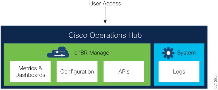
Cisco Operations Hub
Cisco Operations Hub is an application and service hosting platform tailored for the cloud-native era. Cisco Operations Hub hosts applications and services essential to managing the Cisco cnBR, including real-time telemetry, statistics, and log collection as well as providing centralized external management access
to IPDR and SNMP data.
Cisco cnBR Manager provides essential tools for managing a Cisco cnBR:
Metrics & Dashboards: Provides real-time visualizations of service & health metrics along with other information about Cisco cnBR, and DOCSIS network elements.
Configuration: Provides a collection of management tools to view, import, export, and modify Cisco cnBR and RPD configurations.
APIs: Provides a programmatic interface to retrieve configuration, metrics, and other information about Cisco cnBR and DOCSIS network elements.
cnBR Core
The cnBR Core interacts with RPDs to:
receive cable modem (CM) data.
process CM control plane messages to establish and maintain modem sessions.
forward upstream and downstream data between the modem and IP network.
It also captures the KPI health of the modem and RPD network, and provides a management interface for DOCSIS features and
telemetry data, including service flows.
Remote PHY Device
The Remote PHY Device (RPD) provides analogue RF connectivity to the cable modems and digital connectivity to the CMTS Core
(cnBR).
Cisco cnBR Deployment
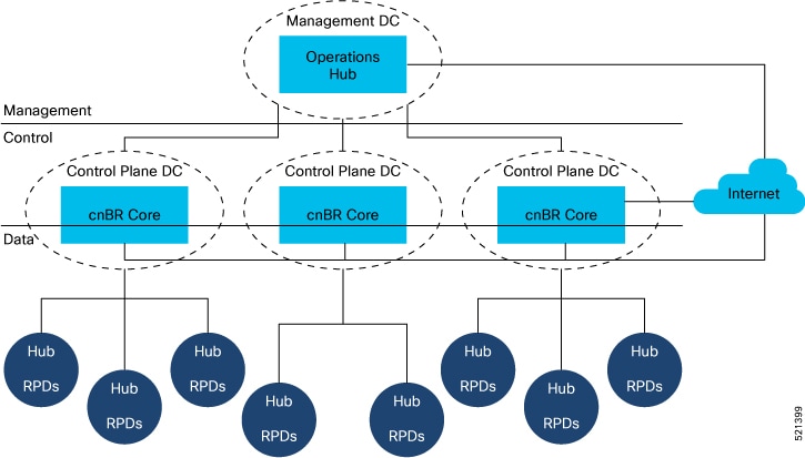
The following figure depicts a typical Cisco cnBR deployment that separates management plane, control plane, and data plane
components.
Figure 2. Typical cnBR Deployment
The management plane components, which include Operations Hub, are centralized within a central data center.
The Cisco cnBR, which contains the control plane components and routing for the data plane, is hosted within regional data centers.
The RPDs within hubs around the hub may connect to these regional data centers.
Because the entire solution has high availability, there can be no single point of failure, especially in the data plane.
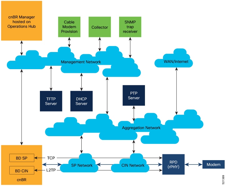
The following diagram shows the components and networks that are configured when a Cisco cnBR is deployed in a typical service provider network.
Figure 3. Network Components
Different networks and their purposes.
Network
Purpose
Aggregation
The aggregation network provides a nexus where necessary network paths converge to provide access to all necessary services.
Converged Interconnect Network (CIN)
The CIN network is well defined in the Cisco cable architecture and brings the cable modem traffic that has been converted
to IP traffic into the digital DOCSIS network. The CIN network connects to the aggregation network for non-CMTS data traffic,
such as PTP timing and RPD provisioning.
Management Network
The management network provides management-level interaction between the Cisco cnBR components and back-office services, such as IPDR collectors, SNMP trap, receivers, and cable modem provisioning and monitoring.
SP Network
The service provider networks provide a path for the cable modem traffic that is processed by the CMTS to reach the internet
from the service provider side of the network.
WAN/Internet
The WAN/Internet network provides a path for the cable modems to send traffic to and receive traffic from the public internet.
These networks may be realized using one or more routers configured for each network.
The TFTP, DHCP, and PTP capabilities are required to be part of the solution and may be connected to different networks than
those depicted in the figure. The PTP, DHCP, and TFTP address are configured within the Cisco cnBR.
The green boxes represent common service provider management features. In the past, cable modem provisioning and monitoring
used information from the CMTS collected through SNMP MIBs. However, going forward, the preference is to move to REST APIs.
In the Cisco cnBR, the CIN and SP bridge domains must be configured. The CIN and SP bridge domain
configurations provide first hop routing information to correspondingly named
networks.
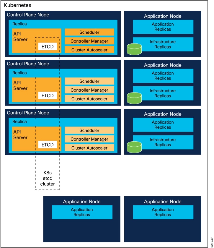
Kubernetes Platform
The Kubernetes (K8S) platform is deployed on VMs. From Cisco cnBR 21.2, bare-metal deployment is also supported.
The Cisco cnBR and management plane services are deployed as microservices within Kubernetes (K8S) container orchestration clusters. The
Kubernetes platform supports deployment of replicated restartable microservices, where requests are routed and processed.
Services are therefore highly available and scalable through redundancy.
To be hardware redundant, the K8S management functionality must be spread across separate nodes, either as bare-metal servers
or as VMs hosted on separate servers as shown in the following figure:
Figure 4. Kubernetes Platform
Similarly, the application load must be spread across worker nodes that are independent of the K8S control plane nodes. Separating
the application workload from K8S control plane nodes protects the K8S management services from being impacted by the application
workload.
The Cisco cnBR functionality and Cisco Operations Hub are hosted in a common cloud platform.
Cisco cnBR Network Topology
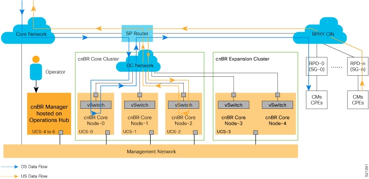
A typical Cisco cnBR network consists of Cisco cnBR core clusters, a SP router network, and Cisco Operations Hub, which hosts the cnBR Manager application. The following figure shows the core components and their inter-connections.
Figure 5. Cisco cnBR Inter-Connections and Data Flow
Core Components of Cisco cnBR Network Topology
A highly available Cisco cnBR core cluster consists of three or more worker nodes, which provide core functionality of traditional CMTS: for example, DOCSIS
control plane, data plane, and DOCSIS applications.
SP Router forwards L3 packets between the uplink core network, RPHY CIN, and cnBR core services.
Cisco Operations Hub is built in its own cluster and provides operation and management-related functionality in the Cisco cnBR system: for example, configuration, monitoring, and alert management.
Cisco cnBR Expansion Servers
Feature History
Table 1. Feature History
Feature Name
Release Information
Feature Description
Multiserver support
Cisco cnBR 20.3
You can install a Cisco cnBR cluster that includes 2 expansion servers, which is a 5-server cluster.
A Multi-Node cnBR can be deployed with increased compute capacity to accommodate larger scale deployments. Additional Cisco
C220 M5 UCS Servers, which are called Expansion Servers, can be added to the Core 3 Node UCS Server Cluster to run additional
DOCSIS Nodes. Cisco cnBR currently supports Static Expansion deployment. The Expansion Servers must be prepared and connected per the Prepare Supporting Software Components procedure in the Set Up Cisco Cloud Native Broadband Router Components section together with the Core 3 Node UCS Server Cluster before the initial cnBR cluster deployment.
Inter-Connections Between Core Components
The SP router connects directly with the data center (DC) network to access multiple Cisco cnBR core nodes. The configuration is based on network virtualization technology that the UCS vSwitch uses, such as VLAN or VXLAN.
Cisco Operations Hub communicates with the Cisco cnBR core clusters through internal RESTful messaging, which in turn is through the high-speed Management Network. The Management
Network also transmits real-time telemetry data exported from Cisco cnBR core clusters to Cisco Operations Hub.
All data traffic goes in and out of the Cisco cnBR core cluster for corresponding processing. The SP router acts as a hub.
Different service groups (SG) are managed by different Cisco cnBR core nodes. For example, in Cisco cnBR Inter-Connections and Data Flow, SG-0 is managed by cnBR-Core Node-0, while SG-n is managed by cnBR-Core Node-2.
Control Flow
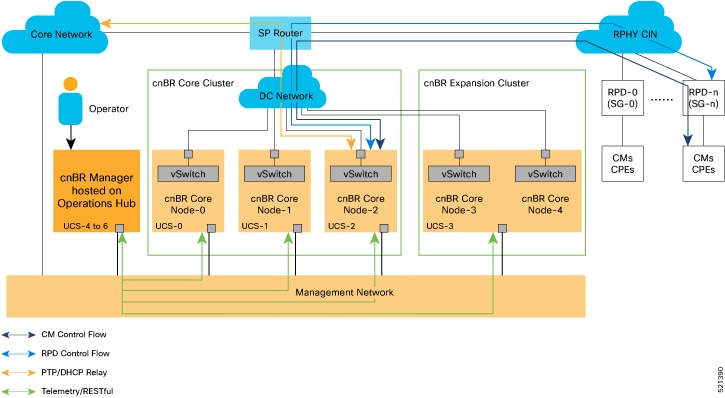
As shown in the following figure, network data flows between the subscriber devices and the Cisco cnBR core for control and data. It also flows between the Cisco cnBR core and the Cisco Operations Hub for management.
Figure 6. Cisco cnBR Control and Management Flows
The major Cisco cnBR control and management flows are:
Cable modem control flow—between DOCSIS service and cable modems, for cable modem provisioning and management
RPD control flow—between RPD service and RPD nodes, for RPD node provisioning and management
Control flow—for PTP and DHCP relay service
Cisco Operations Hub management flow—between Cisco Operations Hub and Cisco cnBR core services, for telemetry data export and RESTful interface messaging
 Feedback